First-Hand:Philips Telephone Exchanges and Denmark, 1960-1970: Difference between revisions
No edit summary |
J.vardalas (talk | contribs) m (First-Hand:Philips Telephone Exchanges and Denmark moved to First-Hand:Philips Telephone Exchanges and Denmark, 1960-1970: Author asked that title be amended) |
(No difference)
| |
Revision as of 15:52, 9 March 2009
December 1960: ”I never dared sell that”
During the trip when an agreement with JTAS was made to supply the test exchange ETS 3 to them, Reinders, who was sales manager at PTI in Hilversum, said: “The only telephone system I ever understood is the manual Magneto system. And that is as well. If I understood the complicated systems we make today I am not sure I dared sell them”.
About this time, Pierce, who was head of the Bell laboratories in the USA, made a statement comparing computers and telephone exchanges. One must remember that computing at that time meant batch processing, i.e. data and programs were prepared on punched cards, carried to the computer, read-in and processed, whereafter the result was carried back to be post-processed. It was quite a while before terminals at a distance became a rule.
Pierce said that the difference between computers and telephone exchanges was that in a computer a calculating error was a catastrophe while a total break-down was a minor nuisance. In a telephone exchange it was just the other way round.
A calculating error in a computer may result in a wrong bank-statement or a wrong salary payment, and that is a catastrophe. In a telephone exchange it would normally only result in a wrong number, and then you just apologize, goes on-hook and makes a new call.
A break-down in a computer would be repaired and the stack of punched cards read in again, only resulting in a minor delay of the result. But when a telephone exchange breaks down it is impossible to call police and ambulance. The customers must have the assurance that the exchange is always ready to serve them.
March 1961 to October 1963: ETS 3 development
During the trip to KTAS and JTAS in the end of 1960, when a final agreement was made with them on supply of ETS 3, de Kroes, head of development of exchanges in Hilversum, asked me again whether I would move to Holland and take part in the development of the exchange?
I discussed it with my wife and as the housing situation was still bad in Holland we agreed that we could accept, provided the Dutch found us a flat and Philips paid all extra expenses in connection with the move. Otherwise we had no special conditions like an allowance for being away. It should be just as a continued employment in Copenhagen.
The result was that I continued getting my salary in Copenhagen. Then special items like pension payment could continue unchanged. I had what we needed for our daily expenses transferred from my Danish bank-account to a Dutch one.
The condition about extra expenses turned out to be very lucky. It appeared that a flat in Holland is delivered to the resident in a quite other condition than a flat in Denmark. When we could finally move in (2 months after we had come to Hilversum) we found a flat with concrete floors, with no heating and no major kitchen utensils except for an absorption refrigerator (which the builder must have got at a very low price!). But Philips paid for wall-to-wall carpets, an oil stove, a range and a water-heater, items which were part of a Danish flat and which would therefore be unnecessary for us when we moved home. It would be the headache of Philips at what price they could pass them on to the next inhabitant.
As for the refrigerator we were glad to have taken our own, with a compressor, with us from Copenhagen. We did not use the one with the flat much.
Construction of ETS 3
How was ETS 3 constructed? I shall here only provide a short description, with weight on the persons responsible for the individual parts. A more technical description is found in an issue of “Teleteknik” from early 1968.
The exchange had no. 3 because there were two predecessors. ETS 1 had been built in the laboratory and was demonstrated for KTAS in January 1959. ETS 2 was a paper project to evaluate whether Philips could on basis of ETS 1 make a saleable product. The result must have been positive, for as a result ETS 3 was made.
But it did not result in a saleable product. For one part, other systems were further developed, for another so much extra was added in order for ETS 3 to function with the usual reliability required in telephony. Another requirement was that it should be possible to keep it in operation and adapt it to changing user requirements for a crew of typical exchange technicians and operators.
The core amplifier
First a word on the exchange components. The logic circuit the whole control was made around was like in the metering equipment two years earlier the core amplifier. It was still the only component which had proved its reliability in professional equipment. Remember that we are still in a period about 10 years after the invention of the transistor, so almost all statements about their lifetime were very loosely based. In general one could only test their longevity under overload and hope that when one in operation loaded them 10 times less, they would live 10 times longer than when tested! Naturally data from actual use were also collected but there were not much experience to draw from as yet.
The core amplifier consisted of a germanium pnp-transistor and four ring-shaped cores. The emitter was connected to ground (0 Volts). The base was via a winding through all cores connected to +2 Volts. The collector was via another winding through all cores connected via other core amplifiers and a resistor (120 Ω) to –24 Volts. Two cores had a third winding with a bias current so they were always kept in their one-condition (except when the core amplifier fired), the other two had some windings through which they could be set to their one-condition by current from other core amplifiers (normally as an and-function, current had to come simultaneously from two sources) and a winding for reading the state of the core amplifier. If it was in the one-condition when the latter winding was energized the base winding would ensure that the transistor would conduct. Now the collector current would give a positive feed-back to the base winding so all four cores were reset properly to their zero-condition. The base voltage, the number of turns on the base winding and the flux in the four cores controlled the duration of the collector current, the resistor limited it to 200 mA. Then current pulses from other core amplifiers might set the two last cores again, while the two first ones had been set immediately after read-out by the bias current.
The whole core amplifier was embedded in epoxy resin and was a block of about 5 cm by 3 cm by 0.5 cm.
The core amplifier had a serious draw-back: it was slow! It was used in circuitry with four phases, i.e. each core amplifier could only be read every fourth clock pulse, and each of these intervals lasted 50 μs, 25 for the pulse and 25 for the pause before the next pulse (which sounds like a long time, but pulse from one core amplifier could trigger a pulse from the next etc., and in the worst case the last pulse should have ended before the next clock pulse). Thus a new cycle started only every 200 μs or 5000 times a second.
This implied that ETS 3 had to be built up in a quite modern way, namely in individual modules for each its separate task. And all these modules had to work in a coordinated fashion.
Thyristor as crosspoint
The other important component was the electronic crosspoints in the selectors, over which speech would pass when they were on. Each contact was a Germanium pnpn-transistor or thyristor as it was later called. It worked as a so-called hook-switch of a pnp and an npn-transistor in combination. Imagine that the emitters are available as the two terminals of the switch and that the base of one transistor is connected to the collector of the other. Finally there is a high-ohmic control connection to the base of the pnp-transistor (and collector of the other). In the idle condition the switch is off, as none of the two transistors draws base-current from the other. The switch goes on when the control connection goes briefly negative. Now the pnp-transistor supplies current to the npn-base, the npn-transistor draws current from the pnp-base, and both are soon saturated. The control current may be switched off, but the two transistors will remain saturated with a small resistance as long as current flows through them. They return to the idle state as soon as this current is interrupted.
The thyristor had of course also its draw-backs. First of all the sustainable blocking voltage between emitter and base (of the pnp-part) was too small. This was dealt with by putting a diode of the type OA 5 in series with the emitter, so the diode provided the blocking. But it meant also that a rather large DC-current had to pass the crosspoint when it was on, in order that the speech-current on top of the DC-current should not be distorted by the non-linearity of the total DC-characteristic of diode and thyristor. Thus the whole crosspoint consisted of a diode, a thyristor and a 27 kΩ resistor to the base for turning the thyristor on, all kept together by a rubber-band. There were about 15000 such crosspoints in the exchange. The rubber-band caused problems after several years of operation.
Another draw-back was the price of the crosspoint. This implied that there could be only one crosspoint, one contact, for each point of the selectors, where from old the balanced connection over a twisted pair in the telephone cable was continued through two contacts for each selector point in the exchanges. We had to have an unbalanced connection through the exchange with one contact per crosspoint and ground as the common return path of all calls. And there had to be a transformer for the conversion between balanced and unbalanced transmission at each end of each path through the exchange. The common return must of course not give any crosstalk from one call to another. Therefore we made all connections between two selector stages two-wire, with one wire to ground in each end. Between two of the stages we even put a transformer in series with the wires, so the speech current in one wire would cause an equivalent but opposite current in the other. All in all we succeeded in having as little crosstalk in ETS 3 as in the electromechanical exchanges with which it was compared.
The selector network
In a telephone exchange all cable pairs to the subscribers are connected to one side of the selector network and all the circuits which serve during calls are connected to the other side. The individual subscriber uses his telephone for only a few minutes per hour, even during the busy hour in the forenoon, and therefore the number of servers is far less than the number of subscribers, e.g. one server per 10 subscribers. The selector network will provide a connection between a calling or called subscriber and a suitable server.
One could imagine such a selector network as a large crossbar selector, with all subscribers along one side and all servers along the other. From each subscriber and from each server a speech path goes through the selector. At each crosspoint between these two speech paths a contact can be made between a subscriber and a server. With 1000 subscribers (as in ETS 3) and e.g. 100 servers there should be 100,000 crosspoints.
This is a very uneconomical construction. Crosspoints can be saved by bundling subscribers in small groups on a first stage in the network, e.g. groups of 20 with 5 connections from each group to the rest of the network. With 1000 subscribers this would claim 50 groups with 100 crosspoints each or 5000 crosspoints in the first stage. There will then be only 50 times 5 or 250 connections to the rest and with 100 servers in a large crossbar switch this would require 25000 crosspoints. Thus the total number of crosspoints is reduced to just 30000 in one go. But in every group of 20 subscribers there are of course only 5 who can be connected simultaneously to a server.
One can go on like this. In ETS 3 there were four stages of crossbar switches between subscribers and servers and a total of about 15 crosspoints per subscriber. The connections between stages were called links and of these there were about one per subscriber. A control circuit called linktester/marker found free links between a subscriber and a suitable server and ordered the crosspoint contacts to switch on.
The thyristors were switched on with a voltage between their emitter and base and they were held on by the current through them from emitter to collector (corresponding to the npn-emitter in the hook-switch). In the crossbar switch the input link was connected to a row of emitters and the output link was connected to a column of collectors. The marking connection to the bases of the thyristors was parallel to the columns. On marking there was only emitter marking voltage at one input link in the whole exchange and the correct column could therefore be indicated in all selectors of the relevant stage simultaneously.
The linktester had a connection to all links between the selector stages. When a connection through the network should be made the linktester asked directly on the links whether they were free or busy to find a free path between subscriber and serving circuit. This implied that a separate administration of the links was not necessary, and that meant again that when a call ended the server could just cut the current holding the thyristors, no message to a link administration to note the used links free was required. This implied also that the reliability could be supported by a duplication of the control circuits where the spare was quiescent (was in cold stand-by) and in the moment it should take over the operation knew nothing about the conditions in the selector network.
A couple of draw-backs compared with electromechanical selectors: One was the attenuation through the exchange. There was a larger resistance through the diodes and thyristors and the balancing transformer in one of the links than through a similar number of mechanical contacts. There was also the leakage current through the base resistances and the linktester connections. All this because the control was done over the same devices as the speech-path used. Our attenuation was about 2 dB, where the old exchanges had less than 1 dB. We were allowed to have this attenuation, but only for a test exchange. There would be no slackening of the requirements if we later used these principles in a commercial exchange!
Another was that the link-testing and the marking process inevitably influenced the speech path. This gave very narrow bounds on the current and voltages allowed, as we naturally had to work within the permissible limits for noise on the speech path.
The selector network with its surrounding circuits for switching the holding current on and off, for separating DC and AC and for connecting its parts to the control circuits was constructed by J. Blom, while the lay-out was made by W. Milort.
M. J. Schmitz
The description has already changed from components to larger system parts. Before going on it would be correct to say a few words about M. J. Schmitz who was head of the ETS 3 development team.
Schmitz had been earlier employed in the Dutch telephone administration (PTT) and was one of the few examples at that time of a person who reached a leading position in Philips Telecommunicatie without being an M.S.E.E. He was qualified in this job and had a nice manner towards us in the group. That he was under quite some pressure from higher up to provide some results and gave in to them was understandable. One version of Murphy’s law which applied very much to Philips then was: “There is never time to do it right, there is always time to do it over”.
I knew Schmitz from my first visits to Hilversum in 1959 and later and met him again as I was in Hilversum in January 1961 and he showed me around in the house where Philips had found us a flat. It was still being built and had long ladders around it. I asked the builder whether it would be ready when we arrived on April 1st? He answered very precisely that no, it would not be ready by then. In my innocence I was sure that it would then be ready April 2nd, but that was my error, nobody had said so! Actually we could move in on June 1st.
Later we also visited the Schmitz family privately. They were brillant when our first daughter was born, really felt with us and helped my wife.
A couple of events: Schmitz told that he had almost been lynched in Amsterdam in early 1945. It was a time with many rumours. The Hunger Winter plagued Holland north of the rivers (not because the Nazis would starve them to death, but provisions could only arrive through the narrow passage via Utrecht as all land south of the rivers had been conquered by the Allied (remember the film “One Bridge Too Far” on the action to push forward to northern Holland in September 1944). And now there were rumours that the Allied had dropped parachuters in northern Holland and had conquered the town of Groningen. Schmitz came out of the PTT building and heard the rumour. He had talked with a PTT employer in Groningen the same day and could tell that the rumour was utterly false. People thought that when he could talk with people in the other end of the country he had to be a Nazi helper and would attack him. He escaped. One more example that it can be unhealthy to bring bad news!
Another event showing his fast mind: We were with Buchner (another head in the laboratory) on our way to a meeting at the PTT in The Hague in Buchner’s car, an Auto Union like mine. Schmitz had an Opel Rekord. On the way we met another Auto Union and Buchner flashed the lights as a greeting as was so often done between these cars. And said to Schmitz that such an enthusiasm was not seen among Rekord owners, they never flashed. Schmitz answered that if he should greet all the Rekord cars he met every day he could as well light up the headlamps as soon as he left his garage and keep them on!
Schmitz was not to see ETS 3 in operation. He died from cancer early in 1966. I do not know how much was due to the delays and constantly postponed terms we experienced in the development of the exchange, but they must have had an effect.
A couple of Schmitz’s expressions made our collaborators from KTAS and JTAS laugh, as it was so obvious what they meant. The delays were unpleasant for them as well and Philips had to announce them and other items in a soft way so they were acceptable for all parties. At these occasions Schmitz always started in one of two ways. Either he said that he had just had a brainwave which he would like to discuss, or he began “Speaking in black and white” and then came what he meant to say.
Control circuits on the subscriber side
Back to the modules of ETS 3. Above the middle of the exchange is described, the selector network, the linktester with its threads to all links between selector stages and the marker with its threads to the base resistor of each and every crosspoint.
On the subscriber side the selector network ended in the subscriber circuits, LC. These were constantly scanned for new originating calls by a subscriber scanner, AO for Abonnee Onderzoeker. And the AO reported the new calls to a subscriber memory, AG for Abonnee Geheugen.
The LC had primarily the components for the connection of the cable pair to the subscriber and the path through the selector network. There was a transformer for the conversion from the balanced transmission on the cable and the unbalanced transmission in the network. In addition the transformer separated the DC on the cable pair and the DC in the network. The latter held the thyristors on during a call, the former supplied current to the telephone sets at the other end of the cable pair (the subscriber loop).
On the network side one end of the transformer was connected to ground, the common return path for all the connections through the network, the other end to the thyristors of the first stage in the selector network. This path included windings on two ring-shaped cores of 2,5 mm diameter, called the M3 and M4 cores.
On the cable side the transformer winding was divided in two, with a capacitor between them and the cable pair connected to the other ends of the windings. Plus (ground) and minus ( 48 Volts) were fed via two resistors of 400 Ω each to the two sides of the capacitor. In addition the DC passed through windings on two of the usual cores, called M1 and M4 (the latter was mentioned above).
It was arranged that the DC on the two sides of the transformer were in opposite directions to reduce the total DC magnetization of its core.
A subscriber connection is supervised by detection of the DC going to the telephone set. When the set is on hook the DC is interrupted, when it is off hook the DC flows. In addition dial pulses are short interruptions of the current. Normally occurring at 10 pulses per second, but in Denmark up to 20 pulses per second was used, i.e. interruptions of down to 16 ms. The M1 core was set by the DC and reset from the AO, and its output was read by the AO. But the AO should not scan the LCs fast enough to detect dial pulses, only to detect new calls. Detection of dial pulses was left to the relevant servers and in order to transfer information on the DC state on the subscriber loop the M4 core was set by the loop current, reset by a 20 kHz pulse train and its output injected in the path through the selectors via the winding on the selector side mentioned above.
When a caller starts a call there is ample time to detect the loop current. It takes about half a second for the handset to reach the ear and this time is therefore available. The AO only scanned fast enough to detect new calls. If the AO should have detected dial pulses it would have had to scan all LCs every 5 ms, which had been impossible, or scan those LCs which were in a dialling state every 5 ms, which would have implied a constant jumping back and forth among the LCs and was therefore also impossible.
There was also an M2 core in the LC, set and reset by the AO and with its output read by the AO. Whenever an M1 core was read and gave an output the M2 core was set. Thus at the next reading both M1 and M2 gave an output and the AO knew that this loop current had been detected.
Finally the M3 core. It was set by the DC through the thyristors, reset by the AO and its output was read by the AO. Whenever there was an output from the M3 core the AO knew that the LC was connected to a server and was supervised by it. Thus the AO could ignore all other signals from the LC.
The AO scanned as said all LCs and detected the output of the M1, M2 and M3 cores. Every LC was scanned about 10 times per second. The logic circuits of the AO treated the signals as such:
• If output from M1, M2 was set.
• If output from M1 and no output from M2 or M3, the AO reported a new call to the AG, with the identity of the LC.
• If output from any core when the AG ordered the AO to detect the state of an LC the answer to the AG was that the LC was busy.
The last point happened when there was a terminating call (a call to the subscriber) and it should be decided if the caller should have a connection or a busy tone. When the AG had ordered the AO to jump to a certain LC and read its state the AO continued its scanning from that LC.
In this way it was ensured that each new call was only reported once to the AG, and there was a line blocking which only made the LC itself busy. Assume e.g. that a handset was taken off hook and placed beside the telephone set. It was seen as a new call and a path through the selector network to a digit receiver was set up and the digit receiver sent dial tone. If no digits were received the digit receiver would give up after about 20 seconds and change to sending busy tone. After another 20 seconds it would give up completely and release the connection through the network. Now none of the common servers nor any crosspoint were busied any more and the output from M1 and M2 would ensure that there was also not reported a new call. This was a silent line blocking (without tone signal) and when the handset was placed on hook the M1 core would be left reset after the next scan of the AO, the M2 core after the scan after that. Thus after about 200 ms the LC would be ready for a new call, originating or terminating.
The largest problem for the AO was that all the M1, M2 and M3 cores were spread over a whole cabinet of LCs. The signal to be detected had an amplitude of about 0.1 Volts so it could easily drown in noise. The detector circuit had the two ends of the output wire through the cores connected to the emitters of two transistors. Each transistor had its base connected to ground through a large electrolytic capacitor. Thus, a proper output would appear as one emitter going positive, the other going negative, i.e. one transistor conducting more and the other less. The detector amplified this signal to provide an input to a core amplifier. A common mode noise signal would make both emitters go positive or both go negative, or make the conductance of both transistors change in the same way. The problem was that this only worked for noise voltages of less than 0.2 Volts or the transistors were driven into blocking or saturation and inevitable differences between them would cause an output anyhow. Fine for a detector with a short detector circuit, but bad when the circuit went through a whole cabinet!
I had read an article on this topic and suggested that the two capacitors should be connected in series between the bases of the transistors, with a resistor of several kΩ between their common point and ground. In this way a balanced signal would give the same (wanted) result as before, while the effect of a common mode signal would be suppressed. It was tested and worked perfectly. But a thorough investigation in another group was denied, they had developed the detector we had to use already. In stead we had to route the detector wire carefully to avoid common mode noise. I suggest that it was the NIH (Not Invented Here) syndrome in action!
New calls were reported to the AG, the subscriber memory. It was constructed around a large memory with data on the subscribers. There were about 40 cores for each of 1152 subscribers or a total of 45,000 bit. This took up a whole shelf in ETS 3! The first 1000 addresses corresponded to the 1000 telephone numbers (directory numbers) of the exchange, the last 152 to lines under hunting groups, i.e. lines to PABXes and the like in the 1000-group. Data for each address were to which LC the number was assigned (there was free numbering in the exchange), metering pulses collected, next number in a hunting group and some characteristics like “only originating calls”, “only terminating calls”, “subscriber meter”, “message service”, “no payment” and the like. Data could be changed from a teleprinter and one was placed in the operator room in Århus so the operators could switch message service on and off for the subscribers of ETS 3.
The addressing was by directory numbers in order to give an answer quickly to the program memory or PG (for Program Geheugen), the coordinator of all the control circuits of the exchange. When a terminating call was made the PG provided the directory number with a request whether it was free? The AG could use this number as an address and read the LC number, send this number to the AO which again could use the LC number directly as an address and answer immediately with the actual state of the LC.
In case of an originating call the AO reported it to the AG with the LC number as additional data. In this case the AG had to scan its addresses until it found one with the same LC number. This address was the corresponding directory number and the AG could inform the PG about the new call with all data necessary for its handling. This scanning took time but as said there was time until the subscriber had the handset by the ear.
There are, however, subscribers who have the handset by the ear already when the public exchange is called, such as users under a PABX. They would sense the waiting time. To cut this time the last 152 addresses in the AG where all lines in hunting groups were placed were always scanned first when the AO reported a new call.
LC, AO and AG were developed by Jan de Ruijter and A. Hiele. I shared for a long time office with de Ruijter and he lived close to us in Hilversum so we met also privately with our wives – who also saw each other quite often while we were on work.
There was a bad moment in 1965 when the AG should be connected with the rest of the exchange. Nothing worked as intended. Why? Because there was a pressure on de Ruijter a couple of years before to quickly produce the drawings so the factory had material from which to produce the AG. He had directly drawn up how the components, the core amplifiers, had to be connected and had drawn lines around those which should be in the same plug-in unit. Without a general view of how the AG should operate. Then W. Smit was called in and he first drew the function in flow charts before this was translated to components. And then it worked!
Special telephone sets
It was important to keep the total price for LC and subscriber installation as low as possible. A normal telephone is called by a ringing signal which is a rather heavy AC current. This signal could not be sent via the crosspoints in the selector network (nor could it pass the transformer in the LC – the frequency was 25 Hz and thus far too low for it). One possibility was to connect this signal to the subscriber pair in the LC by way of a relay. Another – the chosen one – was to send the ringing signal as a tone which could go via the selector network. This implied the delivery of special telephone sets with a tone ringer or rather an amplifier for the tone signal from the exchange, able to operate with so little current from the line that it was still seen as being on hook. This was different from tone ringers as they are found today in telephone sets, they are rather tone generators supplied by the AC ringing.
Only for lines to hunting groups we had to deliver AC ringing, so we did not avoid providing a special circuit between LC and line which could receive the tone signal and in step with this signal connect AC ringing to the line.
This method implied that suddenly other types of subscriber installations also had to be adapted to ETS 3. A very common installation is the use of parallel sets (which is forbidden due to secrecy considerations in e.g. Sweden and Germany). But when one used a set the tone ringer in the other one squeaked and it was in fact possible to hear what was said. The filters for the tone were of course very cheap and not very selective.
JTAS accepted that parallel sets could be removed in the 1000-group in Århus which ETS 3 should serve. But they could not accept removal of extra bells, connected in parallel over the line. So Philips had to develop an extra bell which in itself was easy enough, it was just a tone ringer in a separate box. But the squeaking had to be removed, too. I came on the solution: The tone ringer should only work when the telephone set is on hook and there is a large voltage between the wires of the subscriber pair. As soon as the telephone set answers by going off hook (and making a loop through the microphone between the wires) the voltage between the wires drops. This could be used in the extra ringer, a Zener diode in series with the ringer ensured that the tone ringer could only be active in the on hook state.
Another circuit we had to deliver was a subscriber meter for subscribers who wanted to keep an eye on their costs, e.g. for telephones on loan in a restaurant. At that time the signal to a subscriber meter was a rather high 50 Hz AC voltage, sent in parallel on both wires and with earth as a return circuit (an unbalanced signal). The speech circuit in the telephone set was only sensitive to differences in voltage between the wires (a balanced signal) and should therefore ignore the metering pulses.
ETS 3 could not send such an unbalanced signal through the LC transformer, only balanced signals were possible. Thus, a high-frequency tone was sent to subscribers with a meter which we also provided. It contained a filter so the tone would not be passed on to the telephone set.
Today 50 Hz metering is on its way out to be replaced by the system ETS 3 was the first to introduce. But it is a slow process like so much in telephony. Philips’ PABXes EBX 8000 and 800 could e.g. only work with 50 Hz metering as KTAS and FkT would not invest in new circuits when the possibility existed in the early 1980es.
When we had to deliver telephone sets we could as well deliver modern sets with push-buttons, which gave a tone signal that could go through the selector network. There was as yet no standardization in this field, the first proposal for the system used universally today came from Bell in the USA in 1962. Thus we could choose freely and choose for economical reasons a system with only one tone generator in the set. The push-button selected which tone to be sent. This signal could of course easily be imitated by whistling or speaking into the microphone. So we choose to block the microphone and revert to the on hook state whenever a push-button was pressed. The exchange would know in the relevant tone receivers that when there was a digit signal simultaneously with an on hook state the subscriber had not really gone on hook. But if you were in the middle of a conversation and pressed a push-button there were no tone receiver connected and the exchange could only perceive it as the end of the call.
An item which even in the 1990es could inflame people was the placing of the push-buttons. In 1991 this topic came up again in Denmark and I wrote the following in the engineers’ magazine “Ingeniøren”:
The telephone keys, shall 1 be on top or below?
“The articles in “Ingeniøren” no. 20 and 25, 1991, on the placing of the keys on the telephone keypad makes me join the debate after having followed the ups and downs of the digit 1 over 30 years.
Whether there was a connection between Strowger’s dial and the placement of the keys I do not know. The tone system used today, a low- and a high-pitched tone for every digit and choice of tones with a minimum of harmonic content so they are difficult to simulate by whistling in the microphone, was proposed by Bell in the USA early in the 1960es. Already then the placement of the keys was also suggested and it was in the end of the 1960es standardized in an international recommendation called CCITT Q.23. Reasons for the placing with 1 top left was that terminals on IBM computers at that time had 1 top left, only few people used desk calculators with 1 below left, and for everybody else the natural sequence was to have 1 top left.
The system is based on having for each row of the keypad one of the low tones and for each column one of the high. 1 has the lowest tone in either group, 697 and 1209 Hz, etc. Only two tone generators are necessary, tuned as required by the relevant row and column. If each key had its own two generators one was of course free to place the keys as one wanted, but it would require 24 tone generators and be too expensive.
But already in the 1960es a keypad with 7 top left was used in Denmark. In 1960 an agreement was made between on one side KTAS, JTAS and the Dutch PTT and on the other side Philips concerning the delivery of fully electronic test exchanges with program control and selectors with thyristor contacts to the public networks in Copenhagen, Århus and Utrecht. Philips should i.a. supply special telephone sets adapted to the test exchanges. It was keypad sets and KTAS wanted 1 below left, JTAS did not care and PTT wanted 1 top left. In any case the telephone sets had to be different between Holland and Denmark as the Dutch sets should have only digits on the keys (Holland was fully automatic since 1962), the Danish sets should have digits and letters due to the Copenhagen demi-automatic exchanges called by the two first letters of their name. The tone system was a special one, it was before Bell’s proposal, with only one tone generator and therefore only one tone for each digit. Simulation of digits by whistling into the microphone was prevented by almost cutting the current when a key was pressed. The exchange knew that on hook together with a tone meant a digit, so it worked fine and blocked effectively for simulations.
I worked in the development at Philips and suggested that as it was not a standardized tone system it did not matter that a press on the top left key always gave the same tone, even if it meant 7 in Denmark and 1 in Holland. On the telephone sets the top row was interchanged with the third row and in the exchange it was only one cable form between tone receivers and digit registers which had to be different in the two countries. This was approved and both KTAS and PTT were accommodated. Later the exchange in Copenhagen was cancelled after proposal from Philips, while the two others were in operation from 1967 to 1973.
The next phase is early in the 1970es where the Danish telephone administrations – as the first ones in the World – would introduce keypad telephones as the standard telephone which was supplied with every new subscription then. In the meanwhile pocket calculators had proliferated with a keypad inherited from the mechanical calculators. In these 7, 8 and 9 had to be on top so they could have a longer movement when pressed than 1, 2 and 3. This caused Asger Kjerbye-Nielsen, then head of the research laboratory of the administrations, to propose that 1 should also be below on the telephone keypad (but naturally still consist of 697 and 1209 Hz) in spite of the international standardization. His view won and the Danish standard telephone sets 76E (Comet) and F78 (danMark) got a calculator keypad.
This applied to standard telephone sets. In special sets and operator sets for PABXes 1 remained top left. It would be too expensive to adapt them to special Danish wishes. So except for the Minimat and OCS built at Kirk in Horsens where the operator set is an enlarged version of the Comet set from the same factory, users of special sets and operator sets under PABXes like the Swedish ASB and MD 110 at KTAS, the Canadian SL 1 at JTAS, the Belgian OMNI at FkT and the Dutch EBX, TBX and SOPHO S at KTAS (and EBX at FkT) had to get used to the international telephone keypad.
And now one of the consequences of the liberalization is that if you do not target your product on a small segment of the market – such as is generally done by B&O with their radios and TV sets – you can not afford making a set for the Danish market which deviates from the international standard.
So the only way out for those who insist that the keypad on telephone set and calculator shall be identical is for the time being to buy a Beocom telephone set.”
When this article had been published P. V. Arlev from JTAS phoned me. He and Philip Hansen (who died much too early in the end of the 1970es) were the ETS 3 experts of JTAS and spent a winter in Hilversum to learn about the exchange. More on that later! Arlev was now on pension and would comment a few points in the article.
“JTAS did not care” I had written. It was the head of the laboratory, A. Ortvad, who did not care whether 1 was on top or below. The managing director, Draminsky, cared very much but was not asked before the placing of the keys could not be changed any more. But, said Arlev, he insisted that he would not have a set with 1 below on his desk, so Arlev and Philip Hansen changed an ETS 3 set so it had 1 on top but the frequencies followed suit. Arlev had also had such a set.
Server circuits and their control
Enough about the subscriber side of ETS 3. Now the other side with the server or traffic circuits. There were circuits for internal traffic, VS for Verbindings Schakeling, For outgoing traffic, UO for Uitgaande Overdrager, for incoming traffic, IO for Inkomende Overdrager, for digit receiving, CO for Cijfer Ontvanger, for digit sending, CS for Cijfer Sender. All of it controlled by a server supervisor, VB for Verbindings Bewaker. In addition there was a digit memory, CG for Cijfer Geheugen, for digits to the LME exchanges.
All calls to subscribers outside ETS 3 went to a group selector in the local LME exchange. CG had the task to send the digits needed by the LME exchange to it. The signalling was such that the LME exchange reported back after each digit what it wanted next. The next digit or a repetition of the same one.
There were two types of CO, one for digits from the ETS 3 subscribers (local CO), one for digits from the LME exchange (LME CO). When a subscriber started a call he was first connected to a local CO and after dial tone all digits were sent to it. If the called number was to another ETS 3 subscriber the call was transferred to the incoming side of a VS and its outgoing side was connected to the called number and ringing signal was sent. If the called number was outside ETS 3 the VB passed all digits to the CG. At a certain moment a CS and a UO were called in and the digits were sent via these to the LME exchange. When all digits were sent the connection from the LC to the local CO was switched off and a connection between LC and UO was made and the conversation could begin.
An incoming call arrived at an IO and it called an LME CO. The VB received the digits and would cooperate with the other parts of ETS 3 to connect the IO with the called number.
The local COs, VSes, UOs and IOs were directly connected to the last stage of the selector network. Each VS even with two connections, for the calling and the called side. Each had also a receiver for the 20 kHz off hook signal from the LC (again the VS had two). The UOs and IOs contained a transformer to translate between the unbalanced transmission in the selector network and the balanced transmission to the LME exchange. In addition it separated the DC conditions on the network and exchange sides.
The COs (both local and LME) received autonomously complete digits and delivered them to the VB for analysis. That is: the logic in the local COs could count dial pulses and interdigital pauses and in the LME COs combine the signals from the LME exchange to complete digits. This implied that the VB needed not scan the server circuits as often as if the VB had to scan fast enough to detect every dial pulse. But keypad signals were anyhow quite fast, a new digit might come every 80 ms.
In the direct connections to the network there was a DC generator, which supplied the holding current to the speech path through the network. It was in principle a constant current generator as it should not attenuate the speech signal. During marking there was a high voltage and a very little current, when the last stage had been switched through to the LC and a larger current could flow through the transformer the voltage dropped. In the start we had a problem: The generator actually dropped the current to zero so the speech path was interrupted again!
Blom, who also had made the generator, had to go back to the drawing board and redesigned the generator so it instead gave a constant high voltage whenever the current was below a certain level. At that level it worked as a constant current generator.
The VB was constructed by Jongkind. He later moved to Philips Eindhoven to work with their internal telephone network. They liked to call it “the World’s largest” with about 30,000 extensions in the factory- and office-buildings in this hometown of Philips.
Those parts of the UO, IO, LME CO and CG which faced the LME exchange were in my charge. Schmitz found that it would be a very difficult job because it meant cooperation with another telephone system. The mutual signalling was a problem when one delved into details like pulse times and pulse shapes and their tolerances. But I had first class helpers. Jos Hruschka for the circuitry in the UO, IO and CO and Dick Schuitemaker for the CG. Another help was strangely enough that I would not let Hruschka construct anything before we had a complete description of the signalling. It was the so-called LME DC signalling, where e.g. digits were sent as a series of +/-, /+ pulses.
The main problem was that the Danish administrations had made the job as easy for themselves as possible and had only for every order for a new exchange from LME required that it should cooperate with the existing exchanges. LME had delivered all the other exchanges and could live with that and only tell as much in general terms about their signalling system as they were forced to. And that was far from enough for a new supplier who should cooperate with it! So both KTAS and JTAS were very grateful for the report we made on their signalling system.
We received of course the information the administrations already had and then I started harassing them on the details necessary for us to make our circuitry. During the summer of 1962 I was in Copenhagen with a test box to measure if the information was OK. And then the construction proper started, including the differences between Århus and Copenhagen. When I moved to Denmark in the autumn of 1963 I was replaced by one of the most clever developers in the laboratory, M. Koeman. And in the summer of 1964 the cabinets with UO, IO, LME CO and CG were in the two cities, the three Dutchmen were 4 weeks in Copenhagen and 4 weeks in Århus to test everything (according to the plans made) and it was OK. So all the circuits for the cooperation with the LME exchanges just stood waiting for the rest of ETS 3 until all was delivered and tested in the middle of 1967, 3 years later, and the exchange became operational.
I have met the three also after ETS 3 became operational. Koeman was in Denmark several times to discuss possible deliveries of our next system, PRX. But in 1974 he was going back to Holland after a business trip to Brazil when the Varig-plane in which he was a passenger crashed near Paris. All died.
I only met Schuitemaker a few times. He and Hruschka left Philips when the activities in public telephony were sold to AT&T in the middle of the 1980es. I met Hruschka several times at international conferences, ICC and ISS. It fitted also well that I was for other reasons in Holland in 1975 when he was married and I could come to his reception with a gift from Philip Hansen from JTAS and myself. Again in 1982 as I was in Holland to assist in making a development report on what was later called SOPHO S it coincided with his 25 years jubilee in Philips. On my 50 years birthday.
There were differences between the signalling in Århus and Copenhagen. Here I shall only mention one, viz. double proceed signal in Copenhagen. After every digit in the forward direction an exchange waited for a signal in the backward direction which told whether the next digit should be sent or if the same digit should be repeated. This return signal came from the digit receiver itself and there were only few of these. It was therefore important that the digit receiver was only called in when all the digits it should have were ready in the digit sender. In Århus this was realised by letting the sender wait with starting the build-up of a connection until all 6 digits in the local subscriber numbers were available. In Copenhagen KTAS wanted to reduce the post-dialling delay (between the dialling of the last digit and the start of ringing or busy tone) by already starting the build-up of the connection when the 5th digit was received in the sender. But the last digit receiver should of course not be called in before the 6th digit had been dialled.
This was realised with a double proceed signal. There was not immediate access to the last receiver but only to a circuit before it. That circuit gave a polarity on the incoming line equal to a proceed signal (like the proceed sent by the digit receiver of the previous stage). When the sender had the 6th digit ready it connected a signal receiver (a relay coil). The incoming circuit perceived the current in the line and called the digit receiver. It then connected a relay coil for digit reception and the stop for current was sensed by the digit sender which connected polarity for digit sending. Thus the digit sender should see two proceed signals before sending the three last digits required by the last stage (which covered the build-up of the connection in the 1000-group of subscribers).
Considering that our subscribers had keypads they could dial faster than others. Their post-dialling delay would be too long if we waited with the start of build-up until the 5th digit was received. So we started the build-up in Copenhagen when we had 3 digits available, the sufficient number for all stages except the last.
It was considered one of the major tasks in the development to make this adaptation to LME’s DC signalling, but the method chosen, to first collect all information and then develop, resulted in that this was the only part of the development of ETS 3 which went according to schedule. Of course I could easier resist demands to quickly design circuits so the factory could proceed producing them because I was not paid directly by Philips in Hilversum. I got my salary paid in Denmark so there were no holes in e.g. pension payments.
But do not believe that it was just like that to develop the adaptation. To illustrate this I shall quote from LME’s booklet “A switch in time” on their development of the AXE system. It concerns the change of a transit exchange in Ålborg from AKE to AXE and says: “At a special visit in Stockholm the new system was discussed and Kaj Juul-Pedersen presented a particular solution for exploiting a digital switch to handle the local network. (He admits he later regretted this, since the digital handling of the direct current signalling system proved more challenging in software than anticipated).”
Another couple of special circuits. Release of a connection occurred by sending forward an AC voltage of about 100 Volts. In the LME exchanges it ignited a neon lamp and the current through it operated a relay. We did not have a neon lamp with the required specification and we disliked in general to use this kind of component. In stead we found a 56 Volts Zener diode which we put in series with our relay inside a rectifier bridge. Such a Zener diode was quite a speciality in 1962, only General Electric and Intermetall could provide one. We choose the latter. Our relay for reception of release signal was a large reed relay from Standard Electric, 8 cm by 1 cm by 1 cm!
Digit reception occurred in the LME exchanges with a polarized relay which operated a chain of normal telephone relays. A polarized relay is very sensitive and reacts very fast on small currents in the line. It was used for reception of telegraphy signals. There can be short disturbances (transients) on a line. The polarized relay would react on these but they would be removed by the slow operation of the telephone relays in the counting chain.
We did not like this principle, nor did we believe that we could make the two types of relays cooperate properly. It was too marginal whereas Philips’ principle rather was that everything should work even under the worst of circumstances, if only every component was within its specification.
Thus I constructed a digit receiver according to quite another principle. It used a couple of the large reed relays, which were rather insensitive, as input (one for either polarity). In the worst case, i.e. on the longest lines, one of these would only be operated for about 2 ms during each pulse and that was too short to operate our telephone relays in our counting chain behind the reed relay. But in any case we had about 10 ms from the operation of one reed relay to the operation of the other for the next pulse. We could therefore cope with the problem by letting each reed relay drive a monostable multivibrator which ensured a pulse of at least 8 ms to the relay chain. And it worked. When the circuit was made according to my design there was only added one component and that was only for reasons of the measurement. It looked confusing on an oscilloscope as one of the interesting wires for a short moment, while a telephone relay changed over, was not connected to any voltage. It looked as if there was a short, wrong signal. It was remedied easily by tying the wire to ground through a high-ohmic resistor.
Coordination of the whole exchange
Enough about the circuits facing the LME exchanges. There are still two control modules left which kept the whole exchange together, the program store, PG for Programma Geheugen, constructed by H. Mol, and the recording module, RG for Registreer Geheugen, constructed by Baas.

PG was the first module in Philips’ telecommunication equipment which operated with a stored program. Today we would probably call it firmware, for the program was stored by having the wires for setting and resetting (reading) the ferrite cores woven through them. Every word in the store was selected by a horizontal and a vertical address. The word consisted of three numbers, one for the module which should have the order (e.g. AG), one for the order itself (e.g. test called subscriber) and one for the horizontal address of the next order in the PG. The answer from the module to which the order was sent was again a number for the vertical address of the next order (different for e.g. a free and a busy subscriber) and thus the next program step was decided.
In all other modules the logic (the program) was realized by connections between core amplifiers. The method in the PG was quite novel at that time. Sure there were data in e.g. the CG on how many digits should be dialled for each combination of the two first digits etc. (Copenhagen had a mixture of fully automatic, 6 digit exchanges and half automatic, 2 digit exchanges) woven into ferrite cores in the same way, and the AG had a proper data store with a uniform wiring and setting of ferrite cores controlled by a program, but only the PG had the logic as a stored program.
The RG was the interface to the teleprinter terminals which could change subscriber characteristics, read metering information and read information in case of faults in the exchange.
AG, VB, CG and PG were duplicated due to reliability reasons. We had chosen “cold stand-by”, i.e. the chain of modules not actually controlling the exchange were idle (without clock pulses). In case of a fault which caused the stand-by chain to become active all existing calls could remain active, because it was tested directly in the selector network whether there was a free path for every new call. Thus there was no risk that a new call would be switched into an existing one. But it meant that the “new” VB did not know who had called so metering pulses could not be put on the right counter any more for calls existing during a change over. That was a small problem as such a spontaneous change over almost never occurred. There was a routine change over every night so a chain did not be too long without supervision, but that occurred of course at a time when there was no traffic whatsoever in the exchange.
Another consequence of the cold stand-by was that the RG when it read metering information or changed subscriber characteristics had to awaken the stand-by chain and work with it as well. For metering information the RG had to add the figures from the two AGs to get the correct number of metering pulses.
Mol had described the program of the PG exclusively in lists, which for every address in the PG (each combination of vertical and horizontal address) showed the three numbers for module, command and next horizontal address. Before the PG should be produced it was necessary to check the program, Schmitz asked me to do it and I soon went astray in the lists. Luckily I had read about flow charts and used them myself in my work on the DC signalling. So I translated the lists to flow charts where the program was far easier to oversee and checked it. It may sound improbable but there were no faults in the program! However I could propose an improvement: Two answers from two different modules gave always the same result. I proposed that they should point to the same vertical address and this was approved. At the time there was no special reason to make a vertical address free in this way, but later on there was a need for yet another answer from a module and then this spare address was welcome!
Mol was from the HTS engineering school and was very angry because MSEEs automatically came into a salary class which it was difficult for him to enter. Schmitz was also from the HTS school but had the qualifications to become head of a group. Mol had the technical qualifications as an expert and I understood his anger over his lower salary although he performed better than many an MSEE. He and his wife and their 6 children also lived quite close to us in Hilversum and we met also outside the laboratory. We bought each our first car almost simultaneously and it was a treat for his family when they went driving. With that size of family (and his salary) they had of course chosen the minibus version of Fiat 600.
Mol had lived in Hilversum all his life and had therefore also experienced the “Hunger Winter” from 1944 to 1945. He and other children went in their worn-out shoes (no new ones since 1940) to the villages along the Ijsselmeer, Bunschoten and Spakenburg, 10 to 15 km from Hilversum to beg for food.
Baas developed the RG and had to follow up on what others had not thought about. And what he had also not thought about. Again we had a teleprinter as input and output medium and nobody had speculated over the fact that such a device can not stand to be running all the time. It must have a timer to stop it after a couple of minutes of no activity. And when it starts again one must wait a few seconds before it is running at speed and can detect the data correctly. This was introduced underway. Baas was later involved in the development of Philips’ teleprinter (PACT) in Stockholm and worked for several years in Sweden.
Concurrent engineering
As said there was a pressure for quickly feeding the factory drawings so it could begin producing units for ETS 3. The idea of “concurrent engineering” which seems so new was already our practice then.
The heart and soul behind it was Reydon from the factory office for production preparation. He was often in the laboratory in order to translate our drawings to what was needed in the factory.
Rain torrents and placing on wooden bars
In 1962 we were so far that ETS 3 could begin to be installed in the laboratory. Not the whole of ETS 3 but the modules should as they became ready be tested alone and in cooperation with the other already available modules.
A day with nice dry weather just to a quarter past 5 (we worked from 8 a.m. to 5.30 p.m. with an hour free for lunch) the clouds gathered suddenly and rain began to fall in torrents. It only lasted a quarter of an hour so we could go home at the normal time, but during that quarter it had rained so much that neither the earth or the sewers could cope with it. Hilversum is a little lower than its surroundings (maybe one metre, Holland is flat) and as I went home on bike I saw in the middle of the town how water came up from the sewers. The road under the railway was completely flooded (this happened about once a year). I came home and found that luckily my wife had also not been out in the worst rain.
But there was trouble in the laboratory. It was placed in an old factory hall with its floor at earth level, so rain poured into the hall. There were several telegraphy exchanges in their development phase. This was a major product at that time, especially to airlines (SITA, Society for International Telecommunications for Airlines) and air traffic authorities. Philips had also to United Airlines in the USA delivered a transmission system for ticket booking. From the terminals on the main connections towards the East and West Coasts the answer to a request or a booking had to be less than one second including the time used in the main computer. It worked!
All telegraphy exchanges had their power supplies in the bottom of the cabinets. The rain water seeped in and spoiled them. It gave a serious break in the development.
Of course Schmitz would not risk this for ETS 3. So except that the risk for ETS 3 was minor (no electronic part was closer than 10 cm from the floor) he got hold of some wooden bars of about 10 cm square on which ETS 3 was mounted.
Guards at the gates, de Kroes
The working time was as said 8 a.m. to 5.30 p.m. with one hour for lunch. The latter was fine, otherwise the days might be long for my wife although she got to know the wives of some of my colleagues and they visited each other. I biked home in 20 minutes, had 20 minutes for lunch and biked back in another 20 minutes. Good for my health!
Philips had their own guards at the gates. Clad in black uniforms they received us in the morning and watched that only employees came in. It was before ID-cards with magnetic stripes became general, they relied very much on knowing the faces.
Sometimes they closed the gates at 8 a.m. sharp except for a narrow passage and they asked everybody coming later for their salary-number. For my part I could say that I had no number. I got my salary in Copenhagen. This was the good old days before immediate taxation, so I paid no tax there. But had of course to state my income to the Dutch authorities and pay tax in Hilversum.
In the lab we talked about what became of the lists with salary-numbers? Nobody ever saw any effect of them. We agreed that they probably went to the head of the exchange lab, J. L. de Kroes (later professor at the technical university in Delft). He saw every time his own name and salary-number on the list and threw it away!
Interruptions in the work
There were other things which could interrupt our work in the lab. Here only a couple of very special events:
Beside our lab for development of exchanges (public, private and for telegraphy) a new building was erected for the development of transmission systems, building BD. It was much prettier than our building, which dated back to the 1920es (where Philips had both studios and senders for broadcast in the buildings). It was also much higher, 5 floors and a “wind tunnel” on the roof for the air-conditioning. The old houses had two floors along the sides and a free room in the full height in the middle, for factory purposes.
BD was built by help of a large crane running on rails between our building and the new one. And at last BD was ready and the crane should be dismantled. That day we did not work much in the lab, it was too fascinating to see the crane slowly laid down and then, after the ballast was shovelled out see the long apparatus be rolled out from the factory premises. Turning corners where there was no room for it. If it still exists there are traces on some of the bricks on the corner of building AV, where predevelopment took place.
Another day without much work in the lab was when the rails between the two buildings were gone and the place should be paved. It was done by a true specialist. How he could even out the gravel, plane it and compress it before he laid one stone after the other (hard-burned bricklike stones on their edge as generally used in Holland). Not a stone was relaid, everything was correct at once. We all hang in the windows and admired the work, comparing it with our own efforts when we should lay stones on a few square-meters. And thought about how short a time it normally took before our stones were uneven…
Buchner’s demoralizing effect
Second in command in the switching lab was R. B. Buchner. He spent much of the time thinking. Leaning back in his chair with the feet on his desk. At first he had an office at the side where building BD was erected. And then he moved around the corner. We agreed that the reason had to be that it would be too demoralizing for the developers in the new building to be able to look all day at the seemingly apathetic Buchner. He moved to an office facing the social centre with personnel office etc. We quite agreed that there he could not demoralize anybody. And not because they worked so hard that they never looked through the windows!
Dooren and van Duuren
For some time I shared office with Dooren. He had grown up in Arnhem and experienced September 19th, 1944, there. The same day as the police in Denmark was arrested by the Nazis and sent to concentration camps the Allies tried to seize the bridges over the great rivers (“One bridge too far”) by a major air landing operation near Nijmegen and Arnhem. The bridges by Nijmegen were seized, not the bridge by Arnhem. The Nazis were lucky to have a tank group nearby. The allied forces were defeated, the bridge was blown up. Even in 1949 as I was for the first time in Holland the big road-bridge lay with one end in the water.
After the Nazis had won they would punish the inhabitants of Arnhem for their help to the enemy and declared the whole town as booty. All inhabitants had to leave the town within a few hours, first from the centre, then from the suburbs, each carrying only a small bundle of clothes or the like. It was not the victorious army’s sake where they could find shelter. The troops could then in all ease empty the houses of furniture and other valuables (and spoil the rest). A terrible experience for a boy like Dooren!
A somewhat different remembrance from van Duuren, who was not in our group but in the development of telegraphy exchanges. He told about the great floods in 1953 while he was studying. He and several others worked on a dike in Zeeland. It stretched into infinity on both sides. They placed sandbags along one side of the dike. On that side there was water, already higher than the crest of the dike but held back by the sandbags. And that water was still rising. On the other side of the dike, deep down, was the rest of Zeeland. If the water had broken through nothing could have saved the people, the animals and the farms down there. So the team of students built the wall of sandbags higher and higher until the water finally sank.
This tale fitted with what Jan van Dorsten had told me: He and other students from Leiden were also called in. Jan worked in Does limiting the water damage and did not sleep in several days.
If you meet with 5 Dutchmen you can be sure they belong to 5 different churches and 5 different political parties. But when the water threatens, the big floods of 1953 and the plan for Deltawerken afterwards showed that the Dutchmen can join their forces.
Telex on radio (TOR)
The father of van Duuren was employed in the Dutch PTT and had invented a method for safe telex transmission via radio connections. Their problem is that the connection is not reliable, there is fading and other disturbances making the connection fail now and then. Not completely, but there are holes in the transmission.
The older van Duuren had from the 32 different telex characters (with 5 bit each) made a new code with 35 different characters, each character having 7 elements and with exactly 3 of these being 1-elements. This code was sent and if the receiver did not receive 3 1-elements in a character it asked for a repetition of the character. The 3 extra characters were used respectively as a request for repetition and as idle characters when there were no messages, so sender and receiver were held synchronous.
Philips had a few years before received a large order for telex transmission in Argentine. With the technology of the time van Duuren’s method was too expensive although it was the standardized method and had to be used on international connections. But Philips invented their own method for use on the national connections. I can not remember how this code worked, I think it was based on an extra parity bit to the 5 data bit in each character and (like the van Duuren code) on the repetition of characters which did not arrive correctly (i.c. with the right polarity).
After I was back in Denmark this method came up as a possibility for telex transmission in Greenland. Tele Greenland would like to connect all the small outposts along the Westcoast with troposcatter systems, i.e. radio links without line of sight. In stead a high-power signal is sent into the atmosphere over the horizon. There the signal is scattered by irregularities in the atmosphere and a small part of the signal could reach a sensitive receiver well beyond the horizon. This system was invented during the war (1940 to 1945) and was used after the war between e.g. Western Germany and Berlin, so there was no dependence on wires or radio towers on East German ground.
From Tele Greenland mr. Pingel Rasmussen was an expert with all calculations of the possibilities. Distances and sending power were realistic but with this form of scattering there is a very heavy fading with a certain distribution, so-called Raleigh fading. This lead to long discussions of whether it was the van Duuren code or Philips’ own code which would perform best with this type of fading. These discussions took mainly place between Pingel Rasmussen and Miss Jung from Philips Hilversum. She lived for the mathematics and we others could only sit quiet by and listen when those two discussed.
It was possible to make scenarios (that designation was not invented at that time) where one type of code was the best and scenarios where more came through with the other. A choice had to be made. I do not remember the result, but I doubt that Tele Greenland after all choose other than the van Duuren method for their first radio link along the Westcoast.
Engineer meetings in Eindhoven
The engineers at Philips were members of a “Society for Young Academicians”, Geselschap voor Jonge Academici, with most members in Eindhoven. They issued i.a. a yearbook making fun of many items in the company. E.g. the difference in dress between people in the labs (unwashed sweater and sandals) and sales engineers (suit and a thin attaché case, the less it could hold, the higher your position). Or the witchcraft in the deep cellars: how to make coffee without coffee for our consumption while at work.
The society met also regularly and I particularly remember one to which we were a few who had driven down from Hilversum to participate. It was a meeting with a question session afterwards with the president of the company, Frits Philips, son of Anton Philips who with his brother Gerard had started the company in 1891. Frits Philips went over the annual accounts which had just been published and commented them. And then there were questions.
One of these was why the turn-over in each industrial group was not mentioned? It was shown how the turn-over had developed over the last ten years for each group and the total turn-over for the company over the last ten years was also shown. Thus, competitors could just solve ten equations with ten variables to find it out? Frits Philips answered that competitors were welcome to do so, but the company would not help them. Since then all these figures have become part of the accounts, probably mostly due to requirements on the New York Stock Exchange where Philips shares are traded.
Another question was whether it did not damage our image as a professional supplier that we were so strong in the consumer field? In comparison with e.g. Siemens who almost exclusively worked with professional equipment like telephone exchanges, X-ray equipment, power stations etc.? To this Frits Philips answered that he could promise us that all the companies one could think about were rather very envious at Philips for their strong presence in the consumer field. For one thing the professional customers met our name all the time, in and out of their offices, but it was a good basis for the company that there was this large turn-over in small orders, while orders in the professional field most often came as a big lump so it was close to a catastrophe if the efforts to get in did not result in an order.
Money machines
Another trip, either arranged by the Engineers’ Society or the club in Eindhoven was a trip to Antwerp to visit ITT’s telephone factory BTMC or Bell Telephone Manufacturing Company.
What made most impression on me in their production was to see machines which produced one rotating selector after the other of the model used in the Copenhagen demi-automatic exchanges since the 1930es. This must have been quite a money machine for the development of those selectors must have been written off long ago. Nice for a factory to have that kind of products!
Philips Hilversum had also a product with similar properties as a money machine: Loading coils or Pupin coils as they are called in Europe. Already in the middle of the 1800es the formula for attenuation along a transmission line had been calculated. And found that one could obtain a lower attenuation by increasing the self-induction in the line! It sounds crazy, the self-induction blocks for AC currents and then such an inductance could be used to reduce the attenuation of AC currents (up to a certain frequency)! It is due to the interplay with the capacitance between the two wires of the line that such a surprising result can be obtained.
In Denmark Krarup constructed a cable exploiting this effect. He wound a thin iron thread around each copper wire. This was, however, an expensive solution and the really widespread method was Pupin’s, where the self-induction was lumped in coils for each kilometre or 1.5 kilometre.
Philips had on the basis of their ferrite materials made loading coils and it was for many years a nice product without large problems between order and delivery. This was the time when all telephone connections within a town were in separate wire pairs and where it was therefore important to have a small attenuation between the exchanges. Then it did not pay to invest in transmission systems for many calls on each pair before the exchange distance was more than 20 kilometres.
Military service?
A short time after we moved to Holland I got a letter from the Dutch armed forces: I would not, considering my foreign nationality, be drafted for military service.
Nice to know, but it was definitely not our reason to move to Holland, that I should become a soldier during the two years our stay was planned to last. In addition I found I had done enough for NATO: First 5½ years in the Home Guard while I studied, then 2 years in the Navy, the latter spent on several patrols in the first line in the Baltic Sea. So I would have had something to say if the Dutch authorities had written me differently!
Jan becomes a doctor
In the spring of 1962, a couple of months after our first child, Marianne, was born, Jan should defend his doctor’s thesis at the university in Leiden.
It fitted with a visit by my mother to see her latest grandchild, and we were invited to Leiden to be present at the celebrations.
I was even invited to be present at the defence itself in the very small Senate Chamber at the university. There the strict judges were sitting with the few guests. And the defensor was led in by a couple of his friends from the university and placed in front of his judges. And then the questions and answers began.
The dissertation “Poets, Patrons and Professors” treated the first years of the university and its affinity to Elisabethan England in those years. This was the time when Holland was making itself free from the Spanish rule. Leiden had been besieged by the Spanish for a long time but was liberated (they still celebrate “Leidens onzet”, liberation, on October 3rd every year). The Dutch sought help where they could get it and found it to a large extent in England, who helped not only with the war but also with the foundation of the first university. Later Jan became a specialist in Sir Philip Sidney, one of the many polyglots the former times had, who worked at the university and as a warrior. He was deadly wounded in the battle at Zutphen in 1586.
Well, Jan obviously did well, for he was named a doctor. And in the evening there was a large feast for him in which also we two Danes participated.
“Shuffling Swenn”
P. V. Arlev and Philip Hansen from JTAS and E. W. Ihle from KTAS were a couple of months in the end of 1962 in Hilversum to learn more about ETS 3. I think Philips was pressed to this by the administrations, for it was far too early to be very specific about the system. We had to cover up as best as possible.
As a Dane this became my task. It was with great reluctance I visited them in their office because they had every day new questions which neither I nor others in the lab could answer yet. But the three of them expected answers here and now – fair enough, for the delivery of ETS 3 was (we all believed) just two years ahead.
So it was with dragging steps I went to the other Danes. In addition I had some days a couple of shoes on which did not fit too well. So Hruschka soon named me “Shuffling Swenn”!
The people from Jutland lived in Loosdrecht, in a couple of holiday flats at one of the many marinas with places for and renting of boats (which was of course not active in November), while Ihle lived in a hotel in Hilversum. Years later the owner of the marina, Boshuis, was angry at Ihle, who he believed had also rented a flat. Arlev should have told him that Ihle would not come and always stated that he had indeed done so.
“C’est l’habitude”
I was alone in Hilversum while the three Danes were there. Our first child, a girl, was as said born in March 1962 and my wife did not like the idea of living through the winter in Holland with a small child. All Dutch children had constantly a cold and got their tonsils cut out, for the houses did not live up to Danish standards for insulation and heating. As examples our flat had iron window frames and the windows had a single layer of glass. The heating was an oil stove which smelled more than it heated. The oil came from a 200 litres tank on our balcony which had to be filled up every week. So she went with our daughter to Denmark and they stayed with her parents from early November to early March.
It meant that I could be more with the other Danes and I shall tell about a trip to Belgium in a weekend. Off Friday evening to Bruxelles where we arrived late in the evening. We did not discover that we had passed the frontier before we saw the different road-signs, that close was already then the cooperation between the Benelux countries.
Saturday we looked at the town and went i.a. on a bus trip to the sights. It was Arlev’s idea and it was a good one. As he said: When you arrive in a new town it is the fastest way to get some bearings.
Sunday we went further South to the Ardenner Mountains where we wanted to visit the caves near Han. It was quite outside the tourist season but that meant a quite special tour with our own guide.
Our tour did not go the usual way where you first go by a small train around and up the mountain, whereafter you go through a small door, through the caves and finish with sailing in a rowing boat out of the caves. In stead we went to the “exit” and started by being rowed into the darkness. Well inside our guide turned right and continued rowing. It got darker and darker, the opening through which we had come in disappeared behind a bend and we could not see a thing. We asked how he could find his way and he answered “c’est l’habitude”, it’s routine. Well, soon we could see a weak lamp in front of us and that turned out to be at a small jetty where we embarked. Our guide could switch on the lights in the cave and we went in to see the many stalactites.
Driving on the Ijsselmeer
It was quite lucky that my wife and child were in Denmark over the winter as it became an uncommonly cold winter. In our flat there was ice on the inside of the window frames in spite of all the oil flowing through the stove.
It became one of the few winters where the traditional “Elfstedentocht”, a run on skates along the 11 towns of Friesland in Northern Holland, could be held. About 100 kilometres on skates in biting cold!
It was even so cold that the Ijsselmeer, the former Zuiderzee until it was closed off against the North Sea with a dike in 1932, froze to a depth of more than 50 cm and then the police allowed driving on the lake. That I wanted to try, too, so a Sunday in February I drove to Monnikendam, where you could get on to the lake. From there to the island of Marken (it has later on been connected with the shore by a dike), where you could train ice-driving. Luckily there was place enough for the cars with rear-wheel drive to spin around when they were given too much gas or braked.
After having tried ice-driving you entered the shore again at Volendam and drove along the dike to Edam, where you were back on the highway to Amsterdam. Along the dike there was a wall of snow up to several metres high. I think mostly because the snow was on top of the dike.
In the court
I also came to the local court (kantonrecht) in Hilversum, however only as a spectator.
A morning in the end of this cold winter I was driving to Philips in my car. The sun was low and in a crossing I sensed the reflection of it on the roof of another car. It was just after a bend in the road in front of a school, so my speed was low. In addition, in Holland you adhere very much to the rule of holding back for traffic from your right, unless there is a clear sign of a triangle on its corner to indicate a different rule. In this case the traffic could only come from my left as the road to the right was a one-way street. Further the crossing road was rather narrow. But of course I tried to brake.
That was not enough. It was slippery in patches, so I slipped, hit the other car at its rear wheel so it turned on its side. It was a Citroën 2CV and the driver cut a hole in the roof to get out. Otherwise nothing happened.
The police came and made a report and then I could drive on (thanks to a relatively solid car), while the other had to be transported away.
Some time later a letter came with an invitation to the court where the case against the other was up. I did not need to come but took a day off. Exciting to see how such a case was handled.
I arrived in good time to hear some other cases. They were not handled the way you see in American films or hear about in Denmark. Here the judge played a much larger role in the handling of the cases. It was mostly the judge who was in a dialogue with the parties in the cases.
When “my” case came up I naturally stood up and came forward. The judge looked at me and asked whether I was the defendant or the other? I assured him I was the other. The defendant had not turned up, not even with a lawyer, so the judge ruled that the proposal from the prosecutor for a fine should be the verdict.
Haringvliet
In 1953 Holland was almost drowned under an extreme flood. The Dutch would not have a repetition of that and created the Delta Works, Deltawerken, to close off effectively against the North Sea.
I already said that if you meet with 5 Dutchmen they probably belong to 5 different churches and 5 different political parties. However, when it comes to protection against the sea they can all unite in a common effort. This has long traditions, already in the Middle Age they formed “Waterschapen” to coordinate the fight against the sea.
“Deltawerken” followed the tradition, which was also followed in that there was no speaking about politicians requiring panic reactions completed within impossible time frames, without proper considerations of what should be done within a reasonable economical frame.
Thus the work to protect against a new flood as in 1953 became a 30-year plan. That was the time elapsed before the last barrier in Oosterschelde was built.
But of course the Dutch started where the risk for floods were greatest and those works were completed when we moved to Holland in 1961. It was a sight attracting Sunday tourists for everybody would like to see the enormous works into which their tax money were sunk.
In 1953 the water had penetrated far into Holland, to Gouda 70 km East of Rotterdam. It was high water which had run over the dikes along the Rhine (or Lek as the river is called between Utrecht and Rotterdam). The dikes were built higher and where the canal from Gouda enters the river a movable gate was built to block another flood. This looked like a road bridge turned on its side. The road was the gate itself and the whole “bridge” could be hoisted up and down between two towers. This was one of the first protections built.
Another was the blocking of the “Veerse Gat” in Zeeland. Here an arm of the North Sea had run in front of the old fishermans’ town of Veere, and also here the water had run over the dikes. It was rather easy to block one end of the arm, a dike of the necessary height was made. The other end was worse. If it was blocked the days as a fishermans’ town were gone for Veere. And while it was being blocked there would be a more and more powerful tide which could take the dike material with it.
It was decided to block also this end and to do it with “caissons”, big open boxes with top, bottom and two sides but no front and back. At the front a curtain to block out the water could be rolled up. They were placed in a row across the sea arm, open so the tide could go in and out. Before the last caisson was placed in its gap all the fishermen of Veere sailed out for the last time from Veere with their horns blowing. And when the last caisson was placed and it was ebb all the curtains were raised at one time. Then the dike could just be built up on and around the caissons without trouble from the tide.
While we lived in Holland the turn had come to Haringvliet where most of the water from the Rhine runs into the North Sea. This happens through a river arm called Waal. Shortly after the Rhine enters Holland from Germany it splits up in Neder Rijn to the North along Arnhem and Waal along Nijmegen. A little before Utrecht Neder Rijn changes name to Lek, because a small river branches off to the North, goes through Utrecht and is called Kromme Rijn. The name Rijn follows this small river further to the West through Leiden to it finally runs into the North Sea at Katwijk. Thus you can follow the Rhine through Holland but it is very narrow here and there!
The intention was that it should be possible to block a flood with a row of gates across the Haringvliet. When the barrier blocks the water from the sea and it still comes into Holland from Germany the area inside Haringvliet would be flooded. This should mostly happen in a natural reserve, Biesbosch near Dordrecht. The water from the Rhine should also be deflected to the North near Arnhem, through the Ijssel to Ijsselmeer. This great lake, cut off from the North Sea since 1932, should receive the waters from the Rhine while Haringvliet was blocked. This collided with other interests which would like to see the whole Ijsselmeer drained and cultured. But for people like pleasure sailors the plans to keep the lake as a lake were of course welcome.
Across the Haringvliet a number of gates were built, big plates which could turn on a hinge and let the water flow freely or stop it. There were gates on both the land- and seaside. They were carried by a “Nabla-beam”, called after the Greek letter which is a triangle on its point. Such a beam spanned over the 50 m of each gate. On its flat topside there was made a 4-lane highway (2 in either direction). There are as far as I remember 18 of these double gates. They are turned up and down by the largest hydraulic cylinders I ever saw: their pistons have a diameter of 50 cm!
When we were at Haringvliet in 1962 there was not much of all this to be seen. There was a large square dam around the place where the gates were being built. There was a small boat sailing us to the dam from the town of Hellevoetsluis, and out there we got a description of the works. They were busy making the foundations for the Nabla-beams and I think some of these beams were already on their place. When all was ready and the gates mounted the dam on which we stood should be removed so the water could run through the gates, and then the gates should be connected with the shore with a normal dam. This caused of course an objection from one of the tourists, an economically minded Dutch housewife, who found it a pity that the dam on which we stood and which was built with such a large effort should just be taken down later.
When there had to be open through the gates while the dams to the shore were made it was again the tide and the water from the Rhine which played in. Without free passage through the gates the water would take all the material beside the gates with it. With free passage this would not happen, the dam was started with concrete blocks of about 1 cubic metre each, dropped into the water from a cable railway. This slowed the current besides the gates so much that afterwards earth could be thrown on the blocks without it being flushed away. In this way the dam was built.
Street organ
Holland was (and is probably yet) a funny mixture of old and new. Some say that when they get a notion that the world will soon go under, they will move to Holland, for there everything happens 5 years after they happen in all other places!
An old fashioned thing but a very convenient one was the street peddlers. Every day the milkman came along with his car and once a week the grocer came with his mobile shop. By the way most of these shops were driven by an electric motor and a battery, thus so clean in their operation as the rest of the world started to require it in the 1990es.
A modern thing was the garbage trucks! I was already impressed by them at my first visit in 1949. Every house or flat had a standardized garbage can of galvanized iron. Once a week you placed that can at the edge of the street and when the truck came it was hooked on a carrier at the rear of the truck and emptied automatically. In the truck the garbage was compressed, mostly by turning the whole container on its front end so all fell to the front. Remember that this was a time when garbage in Copenhagen was collected in open horse-drawn cars and the workers had to carry the big cans themselves from the yards and lift them up over the edge of the sides of the cars.
In Hilversum the garbage collectors also took care of large refuse. I remember a day when a whole set of furniture was put out as garbage. The trucks had a room in front for things too big for the cans, and that room was too small for this job. No problem: They drove the truck a couple of times over the furniture and then it could be thrown into the truck.
All Holland used the same kind of can, the only difference being the name of the town, which was pressed into the lid. This gave rise to infinite quarrels with the bureaucrats in the towns when people moved and wished to go on using the can which they had bought once but now had to buy a new one, the only difference being the name on the lid!
Every week we had also a visit from a street organ. It was one of the great Dutch street organs mounted on a cart drawn by a horse. The music was punched as holes in a “book”, a long sequence of cardboard cards. The horse was used to waiting for it drove maybe 50 metres and then stood still while the organ grinders collected from the next group of listeners. The organ itself was driven by a small puffing petrol motor with a rope drive to the big hand wheel. Then both the grinders going around with the organ could collect money. Every Wednesday the organ made a stop just below our flat and it was a treat for our daughter in the summer of 1963 when she was just over 1 year old. She stood on a small balcony at the front of the house and held on to the railings while she danced to the music.
It is by the way harder than one would expect to make a street organ sound nice. Especially the hand wheel must be turned very constantly. The little petrol motor was better at that than I was. There was a street organ museum in Utrecht, and there I once played an old evergreen on one of the large organs. At that time the museum was in an old cloister and the sound was enormous under the vaults! But it sounded horrible for I could not turn the wheel in the right way.
Marriage in the Hague
In the autumn of 1962 Jan had divorced his first wife and in the spring of 1963 he married wife no. 2. Jytte and I were invited, I should even be a witness at the ceremony.
In Holland a marriage with validity for the state is entered at the town hall, and it is your own matter if you want a confirmation in a church afterwards. Therefore a sister to one of Jan’s friends and her fiancé were in 1949 married in the town hall of Nijmegen to get the right to a flat. When they had got one they married in their church and only then they reckoned themselves properly married.
That consideration did not apply to Jan and Gertrude, but her family was active in one of the many churches so there should be a marriage both in the town hall of the Hague, where the bride lived, and in the church. And it should be with style, the men in morning coat during the day and in evening dress in the evening.
Thus, I had to hire the necessary clothes for the festivities (which was quite normal in Holland) so I could fit in with the other guests. And we drove to the Hague, took part in the ceremony at the town hall where I signed the books as a witness to their proper marriage, and then to the church for a new ceremony. And then according to Dutch habits a reception followed by supper for the specially invited ones. The married couple gave also gifts to the witnesses: a beautiful Makkum-plate with the initials of the couple and the witness, thus made specially for the occasion.
Export of furniture
We should return to Denmark in September 1963. In good time I reported to the tax authorities to have everything in the clear on the day we were to leave. Good that I did so, for when all was packed down the remover asked for the document which proved that all tax questions were settled.
It turned out that the Dutch customs authorities are not only interested in goods entering Holland, but also in goods leaving the country. And they had obviously experience with tax evaders running from all obligations. With the control of furniture going abroad they had a chance to get at least a part of the debt payed.
But the tax authorities were inventive. A day my wife was surprised when a man called at our door and requested to be let in. He was a tax inspector and should assess the value of the furniture etc., whether there were expensive furniture, television, paintings or hand-woven carpets. It was a special community tax which depended on the value of these things. I mentioned it to the tax people when I was there on another matter and got as answer that in the communities they had to grass where grass was found to get money enough. Therefore they invented this kind of taxes.
“The Dutchmen are polite”
Coming from Jutland Philip Hansen was full of a nice dry humour. It came i.a. out once in (I think) 1965 when I was almost bristling with pride during one of our visits to Hilversum. The long stay from 1961 to 1963 had of course made it possible for both my wife and myself to talk Dutch so we could get along. It was in fact a greater feat for her as she was not forced to be among Dutchmen all day long. For my part I soon discovered that while I might have been able to make do with English when the talk was about technical matters, there was a lot of private talk in the lab (how is it with your childrens’ illness, where are you going in the weekend etc.) and that was in Dutch. If you wanted to take part in it you had to talk the same language. So that I did.
Talk and talk… I used of course also Dutch when I went shopping but was always answered in English or German. German was not very popular only 16 years after World War 2, but was after all the foreign language talked by most. Luckily they could hear from my accent that I was not a German and then it was OK. Otherwise the Dutch openly admitted that the only thing they liked about the Germans was the D-mark!
Well, I went shopping and could tell Philip Hansen when we met again that in this shop I was answered in Dutch. The lady in the shop had even asked whether my accent was because I was from the Northern province of Friesland? So I was proud!
And Philip Hansen just said: “Yes, the Dutchmen are polite”.
ISS 1966 in Paris
Philips (i.e. Max Hansen) was very open to my need for further education in switching. There were no specific courses in Copenhagen, only the more general ones in sensitivity training and how to assert oneself, so the education in the technical area I had to take care of myself. Mostly through my membership in the IEEE.
Through this I learnt about the International Switching Symposium 1966, which was held in Paris in the end of March 1966. Philips approved that I took part and I took Jytte with me to the conference. We stayed in a small hotel in one of the oldest streets of Paris, Rue de la Huchette, in the centre of the town on the left bank. It was miss Lund, our travel organizer who was also secretary for the financial manager of Philips, Max Poulsen, who arranged the whole trip.
The conference took place in the building of UNESCO near the Eiffel tower. It was an impressive building decorated with art from many countries. I could not help thinking that the money spent on this could probably have been better used on education in the many underdeveloped countries!
There were many interesting contributions. This was the year before Bell put in service the first electronic exchange, no. 1ESS, in Morris, Illinois (and the year before we put ETS 3 in service in Århus). The Bell exchange used computer technology which did not at all live up to the reliability required by a telephone exchange, but that was also not the intension with it. It should rather demonstrate that computer technology could be used in telephone exchanges. The right means would be up to further development. As an example of technology not fitted for telecommunications it had as its store a “flying spot store”, a double cathode ray tube with a common screen. From one side the dots on the screen were written in with charge or no charge. From the other side the charges were read as needed to see the stored data. Such a tube could of course not live up to the expected life time of an exchange, but Bell had also done much duplication of the control circuits, so the exchange as a whole had a reasonable reliability.
There was of course also a program outside the conference. Jytte went on various trips in daytime and in the evenings I could also participate. I remember especially a trip on the Seine river with “Bateaux Mousse”, where we sailed up and down the river through Paris while we enjoyed a first class dinner. Also after the conference we stayed some extra days in the town as tourists in the early spring, before we returned to a snow-covered Copenhagen!
ETS 3 on television
The evening before the official inauguration, i.e. on 7th September 1967, ETS 3 was in the Danish TV. It was a surprise to see almost 30 years later, in October 1996, this broadcast again in a quiz on “When was it?”. It reminded me what was a main item at the time: the tone ringer which was quite new for the users. Could it be heard, compared with the good old bell? And it was sentimental to see Philip Hansen on the TV, he had died much too young. Once again the family laughed at me because the only item I had included in the broadcast was my sleeve while I made a call. So was the tradition: It was JTAS who introduced the system, the supplier was not mentioned – and the reason was not just that the Danish TV handled the advertisement rules strictly at the time.

Hidden agenda (2), ETS 3 inauguration
ETS 3 started its operation on 1st July 1967 and served from that day 1000 subscribers in the centre of Århus. The ceremonial inauguration took place more than two months later, on 8th September. We had succeeded in getting the president of Philips, F. J. Philips, to take part in the inauguration, where he with a call to the managing director of JTAS, Poul Draminsky, could transfer the exchange to him officially. The two telephones used for this call were on each end of the same table.
This was something which gave the telecommunication group credit within the Danish Philips organization, that we were able to get the president himself to Denmark on one of his few visits, in connection with (as Henning Drejer expressed it) one of our secondary activities!
The inauguration itself took place with a speech by de Kroes and with a demonstration via closed circuit TV (Skjold Sørensen, Kejser and one more from the group selling audio-visual systems handled this) where Philip Hansen and I were in front of the cameras. And in the evening there was a large dinner in “The Old Town”.

Here I discovered that Frits Philips was probably not only in Denmark to inaugurate ETS 3. In any case he used the opportunity to convince Gunnar Pedersen, the managing director of the State’s telecommunications administration (P&T), that the TV factories were now so far that if there were colours on the broadcasts there would also be TV receivers available to show them. So this was the time to invest in new transmitters and studio equipment. It did not take long after this before the Danish TV started sending experimental colour TV broadcasts.
The next day, a Saturday, we Philips people were on a long and nice trip on the peninsula Mols. The old gentlemen from Hilversum behaved themselves as young horses. De Kroes and van Doveren ran down one of the large hills. Of course van Doveren ran too fast and fell. Luckily without breaking anything. But he was more careful the rest of the day.
While we were there we saw on a field a grass harvester and we told the Dutchmen that such one was called a Kampmann in Denmark, after the minister of finances, because “it took it all”. Frits Philips caught on to this at once, “as if we called it a Lieftink”.

After a good lunch at the hotel “White House” in Ebeltoft we followed the Dutchmen to Tirstrup where the company airplane PH-LIP, a Fokker F 27, waited to bring them home. And then to Århus where we said goodbye to each other. For my part I went to the station and took a train to Bjerringbro, where my family visited my wife’s aunt.
Cooling in the ETS 3 room, “fitting the job to the worker”
ETS 3 was dimensioned to function without mechanical ventilation in the cabinets at a room temperature of more than 30 degrees centigrade. The exchange itself supplied of course much of the heat, although the “classical” requirement to have no mechanical ventilation coupled with the limited lifetime of germanium transistors at higher temperatures made it necessary that the temperature difference inside and outside the cabinets was kept small. Thus the heat dissipation from the exchange had to be controlled carefully.
But on a summer’s day the room could well become so hot that it was not nice to be in it. The technicians of JTAS complained of it and JTAS listened as always to their remarks. The possibilities for improvement were analysed and a very simple but effective method was implemented: A cooling ceiling was installed above the passages between the cabinets.
This was a sort of horizontal radiators through which ordinary cold water was passed, as this was enough for the purpose. As one of the technicians said: Now it was like a walk in the wood on a fresh spring day!
A fine example of the attitude of the telephone administrations: the environment should as far as possible be adapted to their employees.
X-ray pictures to doctors’ offices
ETS 3 was not the only project in which I was involved in 1967. I was also consulted by the Industrial Division, which had a project for transmission of X-ray pictures from the examination rooms to the doctors’ offices at the County and Municipal Hospital of Odense. I was proud to see both these projects mentioned in the annual report of the Philips concern for that year.
For a sufficient quality of the pictures the normal standard with 625 lines in the picture was not enough. In stead French TV-equipment was used with 819 lines to give the necessary details.
The control was such that when a doctor made an intercom connection from his office to an examination room a video-connection was made at the same time from a camera in the room and a monitor in the office.
The intercom system was from Standard Electric. Originally the architects had designed how the intercom sets should look. This was however a much too expensive solution and in stead the normal type of sets for the system were used.
For the switching of the video connections Philips had a crossbar selector with electronic crosspoints for these broad band signals. The question was how these crosspoints could be controlled from the intercom system such that the connections were built up in parallel.
We discussed this with Standard Electric who were very open with regard to how the connections in the intercom system were switched through. Thus we found a very simple method to solve all problems, with a good isolation between their system and ours. We made them build an extra set of crossbar switches in the intercom exchange, such that each of them was in parallel to one of the switches making the intercom connection. Standard Electric controlled the relay coils of the switches and we had full access to their contacts. There were more contacts for each crosspoint and one of these was used to control the video switch, the others to pan, tilt and zoom the camera from the doctor’s office.
My design had a video selector for each controlling crossbar selector, but during the detailed design in the Industrial Division Christian Jacobsen brought forward an idea which saved several video selectors. He had of course studied the whole principle for the switching of the connections and could therefore propose that if we installed some logic circuits with diodes from the contacts of the mechanical selectors to the video selectors, we could have fewer stages in the latter. A good idea giving less attenuation of the video signal and in addition saving components such that there was a better coverage in the price.
I wonder whether this was one of the first multi-media projects in Denmark?
Philips’ test factory in Utrecht
In the 1960es Philips had built a test factory in Utrecht. Far from the large factories in Eindhoven and with a very special task.
The firm had met the problem in many U-countries that the sales of e.g. TV-sets would be very small during several years. But it was no solution to let the assembly lines in Eindhoven run a few hours more to cover these markets, although that would probably be by far the easiest method for the firm.
These countries had no foreign cash with which to buy TV-sets and – in addition – had the same legitimate wish as the industrial countries, that the sets on sale in the country should be locally produced. A company wishing a good standing with the authorities had to adapt to the rules.
It was obvious that if the yearly production should be a few thousand sets and the production should also pay off, one could not just make a small copy of the big factories with assembly lines etc. Thus the test factory was started with the aim to develop and test alternative production methods. It should produce TV-sets of identically the same types as those coming from Eindhoven, and they should conform to the same quality requirements, such that the finished sets could be distributed on an equal footing with the mass-produced sets.
I visited the factory a few times with Philip Hansen from JTAS, who was very interested in the methods developed there. It was typical for the productions, in which JTAS could be interested, that they would also result in very small series.
What had been found out? That a worker could handle far more operations than was thought possible in the assembly line era (as it was expressed in Chaplin’s film “Modern Times”). You could see a worker starting in the morning at one place, where the TV-sets started their creation. From the left the worker took a chassis, mounted the first components in it and placed it on a table to the workers right. Then the next chassis got its first components. When e.g. six had been handled it was time for a cup of coffee, and then the worker moved to the next place, two steps to the right. More components were put in place here, and after yet another move to a new place the six sets could be finished. Finally, at the end of the day, the worker moved to the last place where the sets were tested and boxed. Thus the worker had the responsibility to find his (or hers) own faults and correct them.
They were very inventive at the factory. During testing the sets should e.g. be screened from the environment by putting it into a Faraday’s cage keeping out disturbing electrical fields. Such a cage was expensive if it should have the required size, so other solutions were sought after. The manager found such a solution during a stroll in a park in Utrecht. It struck him that a waste paper basket made of an iron grid carefully welded in all crossings might be used. It could, so afterwards the sets were tested in a waste paper basket!
The test factory took not only care of development. Whole production lines were made and TV-sets produced on them by the same people who should later manage the production in their homeland. When all was worked through and all initial problems cured, the production line was dismounted and boxed for export to that homeland.
The experience in Utrecht was not just useful for factories in the developing countries. It resulted also in an early introduction of work in self-regulating groups in the common Philips factories with workers changing functions, responsibility for the output of the group etc. So it was little news for me, when Volvo in the early 80ies with a great hulabaloo opened their factory in Kalmar, where each group of workers assembled a whole car and it was presented as the eighth wonder of the world. I had seen similar things in Utrecht fifteen years earlier and the principles were long ago taken in use in the Philips factories.
Personal assistant for Egon Hansen
A consequence of the official opening of the ETS3 exchange by the president of Philips was that Egon Hansen, CTO of Philips Denmark and responsible for all the professional product divisions, saw an opportunity to employ me as his personal assistant. With ETS3 in operation there was not much to do for me in that respect. All the activity should be at JTAS if I had done my work well in teaching them the system. And it would take years before a possible activity in public telephone exchanges could start in earnest. De Kroes had at the opening given a glimpse of a future computer-controlled exchange with metallic connection of the speech paths via reed-relays (the later PRX exchange), but it was still under development and we could hardly start up an activity before it was introduced in Holland.
Thus I could besides the further follow-up on ETS3 work for Egon Hansen. It gave a good impression of the other professional groups like Miniwatt, who sold components to the Danish industry (with B&O as their largest customer), Philips-BOFA, a company owned together with B&O for projects with public address and internal TV-systems, Danish X-ray Technics (DXT), who sold X-ray equipment to hospitals (and had a market share of about 50% with Siemens covering the other 50%) and the Industry Group, supplying electronic control systems to the industry. The groups worked well together, e.g. was a project for transmission of X-ray pictures to the doctors’ offices at the County Hospital in Odense a project for a DXT customer, but it included components from Philips-BOFA and the production of special circuits and the assembly of the TV-switches took place in the Industrial Group, where they could be developed and made.
Both my masters, Max Hansen in Tele and Egon Hansen, had obviously agreed that a question of my loyality towards one or the other could not be allowed. So although Tele was one of Egon Hansen’s responsibilities, I had nothing to do with it as his assistant. Thus I was spared an otherwise awkward situation.
I began in the spring of 1968 and stayed in this job to the summer of 1970, when I was invited to be the only non-Dutch pupil at the first course in the PRX exchange. This would take the whole autumn and as I preferred to continue with the switching technics in telecommunications and as there was another, J. Skjold Sørensen at Philips-BOFA, who could be a first class replacement as personal assistant, I stopped.
During this period Philips Data was started and DXT changed into Philips Medico Systems. Scanticon in Århus started as a training center filled with audio-visual equipment from Philips-BOFA and Philips International Competition for Young Researchers and Inventors started. More about all this below.
Egon Hansen continued after me and Skjold Sørensen to have a personal assistant. One of them was Poul Waldenburg, who came from Medico and later became head of this division, and another was Kjeld Moselund, who was employed while I was assistant and came to the factory. Here he had other ideas about the marketing of the AP Navigator than the management and had to leave the company. The AP Navigator was a brain child of one of the mobile telephony developers, Finn Hendil, who was an avid sailor. The Decca company had established senders in several countries in Western Europe. There was a master and three slaves in each Decca- chain. They rented out receivers, which measured the time difference between the signals from the master and the slaves. Ships bought maps with hyperbolas crossing the line between master and each slave according to these time differences. This gave a very precise location. Hendil developed a device, which calculated and showed latitude and longitude from the Decca signals. This was of course much more attractive for the navigators on a ship than using the Decca charts. But considering that the Decca company was a good component customer, Philips only marketed the device to hobby sailors, not to commercial shipping nor to fishing boats. This consideration was not part of the marketing of e.g. Shipmate, who developed a similar product, and Moselund found that Philips should also not limit their marketing to non-Decca customers. He tried to circumvent the command path (he used his wife, who was employee representative in the supervisory board after me), and that was not well received.
While I was assistant to Egon Hansen, Moselund had sent an application to Philips about employment. One morning Egon Hansen gave me this application and asked my opinion. I read it and found it a very fine paper. Very much to the point, relevant for an employment and a good piece of public relations for the applicant. So I gave it back to Egon Hansen saying that we should not employ him. Egon Hansen looked a little put out and asked what I meant? I explained that if we took him on, he would have taken over both our jobs within a few years. Egon Hansen laughed and Moselund was employed.
Visions for the factory
Just after the Second World War Philips in Copenhagen produced complete radios. It was important to buy Danish, both for the public administrations and for private consumption, and there were high customs duty walls. The same applied in all countries. It was also a condition for Philips Tele receiving the order for carrier frequency systems in 1953 so the Danish telephony network could be modernised with direct dialling throughout Denmark, that we could produce locally. The factory had therefore to implement methods for quality supervision suitable for the professional products they should make. This was not without its problems, but they were coped with when I started in 1959. Max Hansen had started in the factory.
Also TV-sets were made from A to Z in the Danish factory. Philips owned a cabinet making firm, A. P. Hansen in Hvidovre. They supplied the cabinets, which were assembled with all the rest in the factory at Amager. The components came from Holland.
All this changed around 1960. The customs duty walls were removed and Philips choose to concentrate the making of each type of sets in a few factories. We should not any more make complete TV sets in Copenhagen.
This did not mean that Philips should not any more have a production in Denmark. Keeping up the employment remained important, so for some years the factory became the largest supplier of channel selectors in the world. They were supplied not just to our TV-factories within the EFTA (European Free Trade Area) but also to factories within the European Common Market (EF). And they were supplied to other TV-factories just like Elcoma (in Denmark Miniwatt) supplied components to whatever customers they could find. Their turn-over to non-Philips customers was in fact larger than their internal sales. It was necessary to maintain watertight walls between the divisions in order for this to work. E.g. B&O had to be sure that their specifications for new components and new functions could be discussed with their Miniwatt contact, Tor Askerud, without their being revealed immediately to the Philips people developing TV-sets.
At that time a channel selector was a complicated mechanical product. There was a hand-wheel at the side of the set, which you turned to the right channel. On the shaft there was a toothed wheel and a spring loaded tap went into it. So the wheel went from one fixed position to the other. The wheel also turned a set of capacitors and coils for each channel, each set within its own closed iron box, so they could not influence each other. The chosen set was connected to the rest of the set and controlled which program you saw. Thus it was not just electronics, there was a first-rate metalware factory behind the production. The iron boxes for the channel selectors were welded and galvanised so they were completely impenetrable to the radio waves. It was a production of a professional quality and at the same time in a field of sharp competition. Hermann and Janlev were first-rate managers of this production.
Channel selectors were not the only product from Copenhagen. A niche production of professional TV-measuring equipment had also been started. This could never become a large market, so it was suitable for having both development, sales and production in the same set-up. K. B. Mortensen was in charge of development. I.a. test picture generators were developed, which were sold to every TV-sender in the world. Thus, wherever you are, the test picture from your local TV-sender came until recently from a set made at Amager.
One item in a test picture is a perfect circle. If you put up a test picture on a wall and used a TV-camera to transmit it you could not avoid the distortion of the camera. So instead the circle was laid down in an electronic memory: It told for each line of the picture when the circle was passed. Typically for the times when you had to save on memory space (it was quite expensive) the memory only contained one quarter of the circle. It was then electronically mirrored to cover the other three quarters.
Towards the end of the 60ies Egon Hansen realised that the production of channel selectors had had its time. Integrated circuits had been invented and it was obvious that in a few years the whole channel selector would be just one chip among several others in a set. This would not require a metalware factory nor would it be suitable for the factory in Copenhagen. It would just be a small extension of the fabrication of semiconductors at the factories in Holland and elsewhere, where Philips already had such a fabrication. And the chip would then be mounted in the assembly plant, which was also not in Denmark anymore.
If a production in Denmark should be maintained something new had to be found. But what?
Egon Hansen found that the growth during these years in medical applications, i.a. to supervise patients, could be combined with our know-how about TV. Combining in one picture a cardiogram and measurement of the breathing with a picture of the patient as background one could from one place supervise many patients. Thus, in cooperation with the relevant product division, a development was started.
Regrettably, this turned out negatively. The medico-technical applications did not catch on as expected. X-ray equipment remained the area with the biggest turn-over, even into the 21st century!
After my time with Egon Hansen another road was followed: Philips started production of mobile telephones by buying A. P. Radiotelefon. Rumour had it that it did not cost anything, they were bought for their debt to Philips! The production moved to Amager and the development proceeded, now to the NMT (Nordic Mobile Telephony) system, which was the great growth area in the 80ies.
As mentioned the AP badge was also used for the navigator. As microprocessors became cheaper, Finn Hendil built more and more functions into it. And changed it to use GPS satellite signals, which was a good thing when the Decca signals stopped around year 2000!
In 1993 the production of mobile telephones stopped. GSM (Groupe Special Mobile) networks had started all over Europe, but the sets were made at other Philips factories. Thus the big factory at Amager closed down. In that year the number of employees in Philips Denmark fell from 1400 to 700. But it was done in the humane spirit characteristic for Philips. People were taken care of and nobody was really nervous about the future. The production continued unhampered by strikes or unrest up to June 30th, and July 1st the dismounting of the machines started for their move abroad. A good example of the spirit could be found in the development laboratory for mobile telephones. They were asked to continue as if nothing had happened while a buyer to the whole operation was found. And they stayed, none of the “stars” left for themselves, making the whole less worth. Philips kept their word: The whole development was sold to Nokia, who continued at the same address until their new offices were ready. In the early 2000s we even had the pleasure to receive a number of former Philips colleagues in the Philips Veteran Club, although they had in the meanwhile worked at Nokia (or at other buyers of parts of the production). They still felt so much for their old working place, that they wanted to remain in contact with their formed buddies!
Duus-Hansen
One of the companies I dealt with as assistant to Egon Hansen was Philips-BOFA, a company owned together with B&O to sell public address systems, internal TV-systems etc. There were two managers, one from each owner. From Philips it was E. Halger, from B&O it was Duus-Hansen.
Duus-Hansen was a legendary person. Not because of his present function, but during the occupation from 1940 to 1945 he had been in the resistance. He had developed a small radio transmitter, which could actually be housed in a handbag. It made it possible to maintain contact with England in spite of radio location stations. It could easily be packed down after a few minutes transmission and moved on, and as easily set up in a new place. So when the monitors got their bearings, the illegal transmitter was already far away! (See also the interview with Jørgen Palshøj in GHN (he uses the name Duse-Hansen)).
“The House”
One day Egon Hansen told that Philips had been approached by a new institution in Copenhagen, “The House” in the city which should be a gathering point for young people. The organisers would install various public address equipment and had therefore come to us.
I think their intention was that the equipment should be given them as a gift, but we would not just write a substantial check. There was also in Copenhagen a very varied opinion whether it was at all right to use tax money for such a purpose. And how would it develop when it should be user controlled?
Our job was first to find out what they wanted. Thus, a new engineer in Philips-BOFA, Niels Øberg, and I visited “The House” to evaluate their wishes. Øberg should note the details, I was with him as representing the management.
This was the first time I met Øberg, but it was definitely not the last, as it will appear in the following.
We discussed the wishes with the organisers. They wanted public address systems with everything from gramophones and tape recorders to loudspeakers in several rooms in the building, from a restaurant in the basement to various music halls on the upper floors.
Back again, where Øberg noted prices on the list and gave it all to Egon Hansen. He discussed it with his colleagues and I think the result was that “The House” could buy the equipment with a reasonable discount, but not receive it as a gift. This would also not be fair to our distributors or Philips-BOFA, who should live from their activities. “The House” had to find other suppliers!
Philips Data Systems
These years Philips also started developing and selling business computers. One area was to compete with IBM by making big computers for administrative purposes in a new factory in Apeldoorn, Holland. Another was the reasonable step to buy an already well-established company making book-keeping machines, Siemag in Siegen, Germany, take over their agents in other countries, build an organisation around these agents and continue the development of the machines with more and more electronics.
At that time there was a lot of mechanics in the book-keeping machines. They were made as a complete unit with calculating circuits, keyboards, printers with tabulators etc. It should yet take many years before the pc’s appeared with the functions distributed, but the first electronic typewriters (where it was easier to correct faults in the letters) were coming on the market.
The printer in Siemag’s machines was very fast. Faster than a system like IBM’s “golf ball” which came out in these years. Much faster than the type arms in typical typewriters. The system had all letters near the edge of a plastic wheel, each on its own segment. It was called a daisy-wheel, as it looked much like the flower. The wheel turned to the right letter was in front of the paper, and then the wheel got a stroke from a hammer, such that the letter via the ribbon was printed on the paper. The wheel was very light and could therefore accelerate and stop in no time.
Siemag’s agent in Denmark was the office supply firm W. Rolf Pedersen, then situated in Herlev. Data Systems was one of the professional product divisions in Philips and thus under Egon Hansen. So we started discussions with their management, W. and E. Rolf Pedersen, followed by discussions with their employees, who should preferably move to us and continue their sales operations.
The talks succeeded. E. Rolf Pedersen also moved to us for a year to make the transfer smooth. And we employed a number of salesmen on conditions rather new within Philips. With us, only a small part of the salaries depended on the sales figures, but we had to adapt to the conditions on the data market.
They were several people of high quality. A few names are Hædersdal, who stayed with us till he retired, Mårtensson, who was back-up for the salespeople and also stayed until retirement, Schønnemann, who later changed to large computers and bank terminal systems (see later), but left us when we did not succeed in getting an order for terminals in the post offices, and Mogens Olsen, who also stayed until retirement.
W. Rolf Pedersen should of course have a payment for the agency and the final discussion of this took place in Egon Hansen’s office. I could not help saying a joke during this when the moods were a little tense. Egon Hansen found this inappropriate and disturbing, so I felt under the table a kick on my shin-bone. And behaved better during the rest of the talks!
Arenco Electronics
One morning in 1969 Egon Hansen received me with the words: ” Go home and pack a suitcase, we are going to Stockholm tonight”. He had learnt that Philips Sweden had bought the company Arenco Electronics and would find out what that meant.
Philips Data Systems had been started to compete against IBM, Bull, Siemens, Univac, Sperry, ICL etc. in the area of large computers, and we also were busy with bookkeeping machines from Siemag. But what were the Swedes up to?
It turned out that the history was, that the Swedish Match Factory had formed a daughter company, Arenco, to make their match making machines. They had in their turn formed a daughter company, Arenco Electronics, to make control equipment for these machines. But the latter company had thrown itself into other projects and had now three running, which had nothing to do with matches, and were too much for them. However, they might fit into the possible program for Philips Data Systems.
However, it turned out that two of these projects had to be given up. It would not be possible to develop them into profitable products within a reasonable time. One was a betting system for horse race tracks, where the components of the time did not live up to the requirements for real-time operation and reliability within the economical limits. In this respect it was like the telephone exchanges: There were existing systems and a computer-based system had to compete with them with respect to price, reliability and function if a customer should even consider them.
Another product was more a design study, a keyboard for the check-out lines in the supermarkets being opened in these years. A rounded keyboard, which ergonomically should be better than normal keyboards with the keys in a square block. Very likely, but it had to be part of a total solution for the lines, and it would still take years before other than electromechanical cash registers could solve this economically.
The third project paid off, however. Not for Arenco Electronics, who would rather have broken their back on it, but for Philips. Svenska Handelsbanken had called for bids on a terminal system, which should tie together all their branches with terminals and small computers spread all over Sweden and connected through telecommunications to one big cooperating system. Arenco Electronics had obtained the order, but it was too much for them. Philips Sweden saw it right when expecting that a probable development would be towards such decentralised systems and that on the basis of this project a solution could be made interesting many banks and financial institutions. Thus they started an activity different from the activities proposed from Holland. Over the next years they developed PTS 6000 (Philips Terminal System), which was sold in many countries.
Egon Hansen met his Swedish counterpart, Henric Egnell, that evening and heard then and the next day about Arenco Electronics and their products. Egnell was later the first non-Dutchman to become CEO for one of Philips’ product divisions, Data Systems, and later CEO for Philips Denmark, before he retired in the mid-80ies.
West Incineration Plant
I was also involved in the Industry Group’s work with an automatic weighing system for the West Incineration Plant, which was built in these years. Every lorry arriving was weighed and the result printed on a teletype. This would then be the basis for billing for delivered refuse. Data for the print came from several places: The data about the lorry (including its own weight) came from the reading of a plastic card with a magnetic stripe, which the driver inserted in a reader by the weight. Time and weight came from the weighing equipment. The plate on which the lorry stood rested on four steel cylinders and they were a little deformed by the weight of the lorry. Strain Gauges were glued to the steel cylinders to measure the deformation, and the weight was calculated from this. Philips had developed this to have the for approbated lorry weights necessary precision of ±1 0/00. This had been one of the conditions for obtaining this order.
Now the system should be implemented and this was too much for the Industrial Group. But my experience with building systems could be used, so I was involved and made as the first item a description of the output print and where the various points should be fetched. This could then be expanded to how these data individually came from their source to the print, and then the Industrial Group could construct the system.
The teletype itself was not on Philips’ program, so a machine was bought from ITT (Standard Electric), just like the card readers were bought from outside Philips. This gave problems when the equipment was assembled and should be tested. The teletype did not write as it should. We met with the people from ITT at the plant and compared drawings of our two interfaces. We discovered that in the standardised V.24 interface there were two different interpretations of how the signal earth should be connected. I do not remember details about this difference, but we had to find a solution. Preferably without involving too many. It would cost time and money, and especially time was not abundant (there were fines to be paid if we were too late).
There was only one thing to do within the given time frame: I suggested that Philips made its interface as a free contact, which could then be used by ITT to control the teletype. In this way we isolated our earth from that of the teletype, so the problem would disappear. This solution was free for ITT but it cost a few extra circuits for Philips. On the other hand Philips would soon lose more money than the cost of these circuits if we went into lengthy discussions of who should solve the problem. My suggestion was agreed to and carried out, and the weighing equipment performed correctly after the change.
Bow-wow
One of the more curious jobs while being assistant for Egon Hansen was the theft alarm at the home of the CFO, Max Poulsen.
Max Poulsen was a scaring person. However I think it was “more bark than bite”, in any case his closest colleagues stayed with him for many years. Both Miss Lund (who was actually married over many years) and Henry Bertelsen, his later successor and chairman of the supervisory board. Bertelsen was a real performer. In the autumn of 1996 the Philips Veteran Club had its 25th anniversary, and Bertelsen performed as “Old Aunt Agathe”!
Back to Max Poulsen. There had been a break-in close to where he lived and something had to be done to scare the thief if he came nearer. Egon Hansen took it up with me and I went to our professional people in Philips-BOFA, where Skjold Sørensen took up the task.
He choose to scare the thief away with a dog barking. When you pressed the doorbell it started a tape recorder which via loudspeakers sent an angry barking through the rooms. As far as I remember, Skjold could only get hold of a small dog, but he recorded its barking at high speed. When it was later played back at normal speed it sounded precisely as a big and angry Rottweiler!
Did it help? Anyway there was never a break-in at Max Poulsen’s.
Inventions
One of the more curious things by being assistant for Egon Hansen was that inventors often came to him with just the right product for Philips. Each and everyone of them got first of all the question if they had applied for a patent on their idea, otherwise we would not hear about it! The background was of course that there were so many activities in the laboratories of the company which we could know nothing about. But if we rejected an invention after having heard what it contained and a Philips product later came on the market which just vaguely was like it, we could be sure of an accusation that we were inspired by the inventor but did not want him to have part in the profit. It also showed that the inventor really believed in his ideas himself. Thus the requirement that before we would hear about the ideas an authority outside Philips had to have put a date on the idea, so its originator could be unequivocally laid down.
I shall mention two of the ideas we did hear about. One was a toy or a play, where you had half a globe on a pin. The play was to put weights on it so it kept or lost balance. We rejected it because there was no electronics in it.
For seeing the other idea we went to central Copenhagen where the inventor had his office. The idea was a bar code for the identification of goods or other items. The special idea was that the code was written as concentric circles, so whatever direction you read it you saw the same. It was also rejected, as there was as yet years before the rest of the systems necessary to use bar codes had obtained a reasonable price. Remember that we were in the late 60ies and e.g. lasers were very powerful and expensive.
Competition for young scientists and inventors
In 1968 Philips in Eindhoven presented all its European daughter companies for a new idea: They would organise a European competition for young people interested in science and technics. Each country should make its own competition and the two winners from each country should then participate in a final round in Eindhoven, in Evoluon, a permanent exhibition building opened by Philips on its 75 year birthday in 1966 (it did not remain permanent, in the late 80ies it was changed into a meeting center for Philips). Evoluon is still a landmark, built as two deep plates joined along the rim and carried on V-shaped columns.
Egon Hansen immediately started organising the Danish part. With his contacts he soon formed a Danish jury in which I was to become secretary. I should also handle the practical problems. We made brochures about the competition and sent them out. I was very nervous about how many contributions we would receive.
We got about 20 for the 10 prices promised. This was suitable as their quality all in all were fine. The jury choose the winners and they got their prices at a gathering at Philips, where the contributions were also exhibited.
Before that there was a small incident. The jury agreed that one of the projects, an acoustic variometer contributed by the glider aviator Stig Øye, possibly contained a patentable idea. So I got hold of him and we went to the International Patent Office, which Philips used, to get a possible application sent in before the publication of the result of the competition. They told Stig, who really was euphoric, where he might find earlier papers which might block an application. He started this and in the afternoon I had an almost crushed Stig in the telephone: He had found that his idea was earlier presented in France so a patent was impossible. He was also concerned about his price in the Danish competition. In the jury we had not considered possible consequences so I had to find a good answer. I said that we were still convinced that he had on his own worked on his project and was therefore still winner of one of the main prices.
The variometer shows how fast you ascend or descend in a glider. In order not to disturb other tasks Stig had made it to give a tone in a pair of headphones. The pitch increased the faster you ascended and decreased the faster you descended. It consisted of a thermos flask from which a rubber tube went to a pointed glass tube. This was melted into a bulb of a small incandescent lamp so it pointed at the glow wire. Another pointed glass tube was similarly melted into another incandescent lamp and the two lamps were melted together with a hole between them. The latter glass tube was open to the atmosphere. When you ascended the atmosphere became thinner, air went out of the thermos flask and cooled the glow wire in the first lamp. When you descended the other glow wire was cooled. This changed the temperature of one or the other glow wire and thus its resistance. They were connected in a bridge circuit and the output of this controlled a tone generator. One could show the effect by just lifting the device up from the exhibition table!
Stig’s variometer and the other first price project came to Eindhoven where (as far as I remember) Stig got as a price money for his studies.
I took care that all participants got an evaluation by the jury of their project. Of course I had to make drafts of these myself, but I had from the start maintained that this was what we owed them in response to their participation. I was happy that there was not several hundred contributions!
During the next years there were several fine projects from Denmark. One was a yearlong study of crows around The town of Aabenraa, made by Ulf Roed. That year (1970) I went to Eindhoven to assist the two Danish winners with their exhibitions. We had prepared them well with assistance from Philips’ decorator, Eivind Petersen. Ulf had himself supplied one of his bird watching tents for it (a primitive small tent of sack cloth looking very authentic) and luckily I visited on my way to Eindhoven a former colleague from Hilversum, Jan de Ruijter. With his help I learned the names of all sorts of crows in Dutch, which was useful when I was an interpreter during an interview with Ulf for the Dutch television.


A final note: In 2008 I had scanned all my dias from the many years into my pc. I then googled Ulf and indeed found him on the net. After ensuring that I had found the right person I sent him the pictures attached to an e-mail, for which he was very glad.
Another proposal was an idea to transpose the tones on an electronic organ. With a dial one could change from e.g. C-sharp to E-sharp while still using the same keys. Shortly before the Danish competition was finished I was in Eindhoven at an internal research exhibition. An item was proposals for further development of electronic organs, and i.a. showed exactly this function. I could tell this when the jury assembled and the proposal received a price. I was careful to note that Philips worked at the same function in their development in order to avoid a possible accusation that we had stolen the idea if it appeared in a Philips product some years later!
There was also a voice recognition project, originally a final examination project at the Technical University. It could recognise the digits from 0 to 9 and a few other words, but as the developer said: If you knew how the digits were recognised you could better say them in such a way that they were detected correctly.
In Eindhoven one met many different projects from other countries. I shall mention two: An English girl school participated with a device to recognise fingerprints. Certain aspects can be used for classification such that most of the search in the archive could be done automatically. When evaluating this project (and the voice recogniser above) one must remember that we were still in the early 70ies, it took another ten years before the first pc’s came on the market. Programming was still an art in which one should use as little storage space as possible!
Another project was a cat toilet, contributed by a Belgian. It was a big box with a conveyer belt on top. It ran under a container with cats’ gravel, covering the belt with new gravel when the belt moved and the used gravel fell into the box in the other end. When a cat had made the gravel on the belt wet a small current could pass from one side to the other and this started the belt moving.
These projects show the breadth of the contributions and I think it was very inspiring for the participants. The competition continued after my time with Egon Hansen, as far as I remember for a total of 19 years before hard times made Philips stop supporting it. Another contributing factor was also that the public relations man, who had run the Dutch arrangements in all these years, retired.
Office landscape at Elcoma
Towards the end of the 60ies the idea of office landscapes appeared. It was not applicable to our house in Copenhagen, but was implemented in new office buildings.
During a visit with Egon Hansen to Eindhoven this was one of the items we would look upon. Elcoma, the components division whose Danish counterpart was Miniwatt, had recently built a house with such a landscape. So we discussed it with the management there.
Our impression was that for many of the employees the distance to the windows was too long. One could also not save place by having less distance between them if their conditions should be reasonable. To avoid mutual disturbances a certain distance was required meaning the same overall space as with single offices. However fi these points were taken in regard it looked very attractive. There was more contact between the employees than if each sat in his own box.
Already in Hilversum I had found this attractive: That the offices had large windows towards the passage along them. One could follow who came along. When I came to Copenhagen I consequently kept my door open at all times and continued to do this when I moved to Copenhagen Telephone and Tele Danmark.
We also found it funny that there were some people who were more equal than the others: The managers had kept what looked almost as single offices. They sat behind a wall of cupboards with as only access their secretary’s office screened by another wall of cupboards.
Philips’ research laboratories
From the start in 1891 Philips had seen the importance of further development. Something of the utmost importance for the growth of the firm in the first years was no doubt the competition between the two brothers creating the firm: Could Anton sell more lamps than Gerard could produce or was it the other way round?
Early on a laboratory for basic research was established, natuurkundig laboratorium or Natlab in Eindhoven (and later in several cities outside Holland). Their task was to investigate everything which could not yet be further developed in a product division. All parts of Philips participated with an amount of 2% of their turn-over, while a typical figure for the later product development was about 6%. One such development lab was the one in Hilversum, where I had worked on ETS3.
One of the hot topics in Natlab was magnetic ceramics or ferrites. They are perfect for transformers for high frequencies (speech frequencies and up) because they are electrical insulators and therefore suppress eddy currents and their losses. Ferrites was an important part of the telephone transmission equipment Philips made. But ferrites with other properties were also developed, e.g. as permanent magnets, useful in Philishavers and bike dynamos. And ferrites were developed with a square hysteresis loop, i.e. they were first demagnetised when a rather large field was applied to them in the opposite direction. If such a ferrite was used in a transformer it would result in large losses, but they were the right thing for memories in the first large computers. Even up to the PRX exchanges from Hilversum (on the market in 1975) ferrite memories were used. Philips was for many years the largest supplier of memory cores to IBM. The single core got smaller and smaller while the total capacity of the memories grew, so it was good business.
Philips also followed the policy that as soon as an investigation led to a patentable result they applied for a patent. In this way there was something to trade and one of the best deals was properly when it was discussed with the Bell labs in the US to interchange licences on ferrites and transistors. With access to these patents Philips could start a factory in Nijmegen, which became one of the biggest suppliers of transistors in the world. It was later a major supplier of integrated circuits. Not standard circuits like microprocessors and memories, but application-specific circuits used in much entertainment electronics.
The policy of Philips was not only to sell patents at a high price. Often there was an advantage in letting everybody use the inventions at no charge.
This sounds like foolishness, but it was not. An example is the Compact Cassette. It was given free for use by everybody, but only because Philips realised that either the market would be split by many suppliers each with his offer of music. Or all suppliers made the same type of cassette, players for this type and issued music on this type. In that case the market would be much bigger and that would be an advantage for all.
One can also philosophise on the responsibility of the technicians for the products they make. The Compact Cassette was one of the prerequisites for the revolution in Iran, which sent the shah into exile and brought Khomeini home. In his home in France he recorded speeches on cassettes, they were mass-copied and smuggled into Iran, inciting people. But not even the shah did ever reproach Philips that they had made this propaganda possible!
Philips tried the same with videocassettes in competition with Sony and JVC. For some years there were three competing systems on the market and it was Sony and Philips who lost. JVC’s VHS-system became the de facto standard.
But Philips succeeded again with the Compact Disc and the Digital Video Disc (CD and DVD), which were developed in cooperation with some of the competitors. All of it thanks to standardisation and that the developing firms allow the use of their Intellectual Property Rights. by everybody who will make the standardised products.
Back to Natlab. They made basic research which had not always a connection with Philips’ activities in electronics. An example is the investigation of the possibilities in the Sterling-engine, which took place in Eindhoven during several years.
Sterling was an Irish preacher, who in the 1840ies came with an idea for a new type of motor. The principle was that a certain amount of air moved between a hot and a cold chamber, such that it alternatively expanded and contracted. This moved a working piston. The hot room could be heated from the outside and the motor could therefore be held in operation by e.g. a coal fire. In Philips’ design there were two pistons, a moving piston and the working piston. The moving piston had always the same pressure on both sides and was thus easy to move. It moved the air between the two chambers. Consider a situation where all air is in the cold chamber and therefore has the smallest volume. Now the moving piston moves the air to the hot chamber and its pressure increases. This forces the working piston to move. The moving piston then moves the air back to the cold chamber, it contracts and forces the working piston to move back again.
Various patents were applied for. One of them was for the “rolling sock” principle. For a good working normal air could not be used, It had to be hydrogen. This has very small molecules and can leak through almost any type of tightening. Then the “rolling sock” was invented and the inspiration could very well have been how to get a sock on a foot. As Edison said: “An invention is 1% inspirstion and 99% transpiration”. The tightening formed a hose around the piston, fixed to the piston and the cylinder. When they moved the “sock” moved up and down in the space between them, but there were no place for the hydrogen to escape along the two surfaces gliding along each other.
A few motors were made according to the Sterling principle, but only for the pleasure of the top management, who e.g. had such a motor in a pleasure boat. However, the patents were worth something but I do not think they could pay for the research. They were sold to car factories and to others (like United Sterling in Malmö), but were not in the start of the 21st century used in a car. Very much like the Wankel-motor, which is also only used in experimental cars. The Otto-motor is hard to beat!
Philips used, however, the reverse Sterling principle in a product, viz. in a generator for liquid oxygen. Reverse because here the working piston was driven against the pressure. Let us assume all air is in the cold chamber. Now we withdraw the working piston, making the volume larger. Thus the temperature of the air decreases. The moving piston then moves the air to the hot chamber, where it is heated. The working piston then compresses the air, making it even hotter. This heat is removed by cooling the walls and the now cold air is again moved to the cold chamber, where it is expanded and further cooled. With water cooling the hot end, one could have liquid oxygen dripping off the cold end!
Dropfoot
But there were other projects in the research labs. An example is an apparatus to help people with a dropfoot.
It is a sickness where the hindmost foot at every step remains hanging down, so it is rather drawn along on the tip of the toe. It must be thrown forward for the next step. In most cases it only hits one foot.
What had been invented was a stimulator for the muscle which lifts the foot in the form of an electrode around the sick leg. It got its signal from an electronic unit, and it was again triggered by a contact in the shoe on the sound leg. When the weight is on the sound foot the muscle in the sick leg was stimulated, lifting the sick foot.
Chief engineer Borregaard at Jutland Telephone had a dropfoot, and when we first heard about prototypes of the device from Eindhoven it succeeded for Max Hansen to get one to Denmark for use by Borregaard. And it helped him.
After use by him for several years we could use it ourselves, as the driver of the telecommunications division in Copenhagen, Svend Førsterling, had got this sickness. He also used the device for several years and it helped him greatly.
Phantom Cross
Another activity with which I had a little to do was the activity within signalling systems. Partly via Tele, who had a connection with the French firm TRT (Telecommunications Radioelectronique et Telephonique), who also worked with railway signalling. I studied a proposal from them and found here equipment even more professional than within telecommunications. But here human life was risked if the equipment failed. This did not become a new market for us, the traditional suppliers of the State Railways were too well established.
Via the job for Egon Hansen I had also something to do with a Dutch firm working on signalling for road traffic. Not just traffic lights, variable sign boards along motor ways were part of their program. One of their patents was a so-called phantom cross in traffic lights, which made it possible to see if the signal was on even if the sun shined directly into the lamp.
The sunbeam would be reflected by the built-in reflector, and this could confuse a road user whether it was in a traffic light on the street or in a red light on a railway crossing. The phantom cross was two black plates between lamp and reflector, parallel to the direction of the light. The light from the lamp was not damped, but reflected light from the outside would hit the plates and be stopped.
Some time later I noticed that traffic lights from DSI, Danish Signal Industry, did contain such a phantom cross behind the coloured glass. I wrote to the Dutch firm to notify them of this breach of the patent. I never heard about it again. Probably DSI was such a good customer at other points that it best paid off to let the matter rest. In any case there was some cooperation between the Dutch firm and DSI. I once fetched an employee from the firm and drove him to the offices of DSI. He said nothing about the purpose of his visit!
Grundfos
Another request came from the Industry Division in Holland: What could we tell them about the organisation and products of Grundfos, a Danish firm already then specialising in pumps of all sorts.
It smelled of an intention to copy the products, especially the sewer pumps designed to be immersed in waste water which were and is a Grundfos speciality, and I did not like the idea. But OK, what was publicly available I could provide to the Dutch, so that was what I did. Both information about the firm and some product catalogues.
I did not hear more about this matter and Philips did not enter this market area.
Course in PCM transmission
Around 1968 a new transmission system came forward, PCM or Pulse Code Modulation. The difference from the FDM, Frequency Division Multiplex, where the signals all exist simultaneously on the same coaxial cable or wire pair, but at different frequencies, just like the stations on a radio, was that each signal was sampled 8000 times per second and coded into eight pulses, giving one of 256 levels. This meant for each call 64.000 pulses per second, and as a wire pair could (then) transmit 2.048.000 pulses per second there was room for 32 64.000 pulses per second channels. Each pulse represented one bit (binary digit). One channel was used for locating the others due to a fixed pattern of bits recognised by the receiver. Another channel was used for signalling (seizure and release etc.) of the other channels. This gave 30 speech channels on such a line.
The primary reason for this development was that it might make it economical to use transmission systems between exchanges in the cities at distances shorter than 10 kilometers. In stead of using 1 wire pair for each call, one could now use two for 30 calls, one pair in each direction. In stead of digging up the streets when the transmission capacity had to be increased, one could just put electronics in both ends of the line
I participated in one of the first courses held in Hilversum about the new system together with Svend Erik Andersen, Tele’s technical expert on transmission, and with people from the telephone administrations. Electronics were still rather expensive, so to keep the price down there was a common coder for 8 channels. It had to work 8 times faster than individual coders but it was more economical at thet time.
The course was very interesting and with time PCM even penetrated into the exchanges, so I could use the stuff when I later followed up on digital technics. But I also emphasised that it was not my area to work on transmission systems, PCM was an outgrowth on the area of Svend Erik Andersen and our transmission people.
Transmission of telex signals
In 1968 new transmission methods for telex signals appeared. Telex was teletype messages between subscribers. Each teletype could not only type what was written on it but also what was sent from another teletype. There was a network of telex exchanges, much like (but much smaller) than the telephone network. The connection to the exchange was a DC connection and the signals were sent as current/no-current. Each element lasted 20 milliseconds (ms) and 7½ elements, 150 ms, formed a character of which 5 elements held the variable information about the 32 characters possible. Note that I say teletype machines, but actually a teletype in its US form contains 8 information elements, giving 256 characters. With telex one could transmit about 7 characters per second. Not much seen with later eyes, but OK for that time.
Between the exchanges each telex message was in the start changed into tone signals with two frequencies, for resp. current and no-current. Such a connection took up a whole speech channel in the transmission systems.
Digital transmission systems appeared, systems for transmission of each element (or bit). A coding was necessary, as they should still be sent over the analogue transmission systems. One might call the first systems with two tones digital, but the further development should ensure transmission of several telex signals over one speech channel.
Philips developed in their Belgian factories, MBLE (Manufacture Belge de Lampes et Electronique), a system for transmission of 48.000 bits per second (48 kbit/s) over a primary group, i.e. in the frequency band 60 to 120 kHz. This was a band for 12 speech channels. All analogue transmission systems were constructed in the same way, first assembling the channels in a primary group, then assembling a number of these in a secondary group etc. When a primary group contained something else than 12 speech channels it could still be handled as a unit higher up in the hierarchy and be mixed with other primary groups. Only when it was again separated it should be treated in a special way.
The transmission of the 48 kbit/s was done by transmitting each 1 as a pulse, each 0 as no-pulse. But the 1s could not just be sent as a square voltage on the primary group, as then the signal would not at all fit into the group. Therefore each 1 was sent as a short sequence of pulses forming a wave with a basic frequency of 84 kHz. The art was to let this wave increase and decrease in such a way that all the signal energy was kept within the primary group, while also ensuring that the amplitude of the wave was zero where the waves of neighbouring bits would have their maximum, as each wave train lasted more than 1/48,000 seconds.
The sender had a series of pre-programmed amplitudes with a small interval, such that there were maybe 10 of these amplitudes during 1/48.000 seconds. When a 1 should be transmitted these amplitudes were read and via a low-pass filter sent to the line. This ensured the right form of the signal. In the receiver the basic frequency of 84 kHz was filtered out and converted to 1s and 0s.
We received a test equipment to be tested at the administration’s lab in Copenhagen. It worked OK, but did not result in a sale. The capacity was too great for the need for telex connections.
How many telex channels could be transmitted over a primary group using this equipment? Basically there was a bit every 20 ms. But telex was not synchronous. One thing was that each character ended with a bit of 30 ms, another that there was a tolerance on the speed of ±10% (that was why there was a longer bit in the end of each character, it adapted a fast sender to a slow receiver, which had time to finish each character before the next one arrived). The transmission had therefore to transmit bits of a varying length, however of at least 18 ms.
One way to do this was by multiple scanning, i.e. for each telex connection a bit was transmitted every 2nd ms with the value of the relevant element. That is, for each element 10 bits would be sent with the same value. The receiver got the elements with a precision of ±1 ms or ±5% of the duration of the element. Using this transmission each telex channel required a pulse every 2nd ms and with 48 pulses per ms (48 kbit/s) 96 telex connections could be sent, 8 times more than was possible if only one telex channel was sent per speech channel in a primary group.
But a method was found to triple this number. The time for each shift from 0 to 1 and the reverse was coded. Every sixth ms an impulse was sent for a channel and if the telex signal contained a row of 1s, a 1 was transmitted every time. When the telex signal changed to 0, the next bit would be a 0 and the two next bits told with 00, 01, 10 or 11 in which quarter of the 6 ms before the 0 the change had been made.
Thus not only could 288 telex signals be transmitted on a primary group. The precision was also increased to ±0,75 ms for each change. However, it will be obvious that while multiple scanning could transmit arbitrarily fast shifts, only with less precision, the new coding required the transmission of three bits before information about another shift could be sent.
As said, it did not become a saleable product due to a lack of need for the high number of channels. There were also other developments, notably at Siemens, who had made the telex exchanges.
Modems for the change of data signals to tones were being developed and could send not only the 50 bit/s of telex, but also 300, 1200 and 2400 bit/s in a speech channel. For telex Siemens had also developed another coding method. In 120 ms they transmitted 6 bits, a start and 5 databits for each character, followed by a series of stopbits until the sender had the next character ready. When the receiver had read the 6 bits it would wait for the next startbit and read the character in the next 5 databits. At the nominal speed of 1 character every 150 ms there would be three stopbits for every 2 characters, alternatively 1 and 2. If the sender ran faster there would be less stopbits, if it was slower, there would be more. The receiver could adjust to the original speed towards the receiving telex machine. Thus, each telex connection required 6 bits every 120 ms or 50 bit/s. With 2400 bit/s each speech channel could transmit 48 telex channels, but each direction required its own wire pair, so the actual increase was to 24 channels per speech connection.
This number was a much better fit to the needs for links between the telex exchanges and required only 1 speech channel in stead of 12. So this solution was the winner.
An evenings trip to Århus
Once in 1969 (I think) I had just returned from work when the telephone rang. It was one of the operators in Århus, who – full of apologies – told me that they had a problem with ETS3. They could not call the technician on duty, as there was a strike on, and they could not reach Philip Hansen. My name and number were the next on the list.
Of course I said they had done the right thing and that I would come over and see if I could help. I got busy getting a plane ticket, a room in a hotel and packing a suitcase. I arrived around 11 pm and the operators were impressed that I had come so fast. For me it was quite natural that when a customer was in trouble you were available both day and night.
Luckily the problem was rather small, mostly that the manual was not clear enough. The operators had made a mistake when changing some subscriber data from the teletype. It would have been worse if there had been a fault in the exchange. I lacked the routine acquired by the technicians in handling such problems. This was a recurring problem, to be back-up for the technicians with a daily routine without such a routine myself.
Well, the problem was solved and the hotel waited. The next day I went back to the operators where there was nothing more to do, and then back to Copenhagen.
ETS3 sold to Jutland Telephone
In 1969, when ETS3 had been in operation for a couple of years, Philip Hansen asked me if Jutland Telephone might buy ETS3? They would keep it in operation for more than the agreed 5 years, due to the good experience with it.
My attitude was that Philips had written off the equipment as a development cost. It was not that type of exchange we would market in the future. Already when the exchange was officially opened in September 1967 it was said that the next system would use reed relays in the speech paths. Jutland Telephone had also invested a good deal of money in the teaching of technicians etc. So I found that they could buy the exchange for the symbolic amount of 1 Danish krone.
I also considered that if they bought ETS3 we would not have the obligation to remove the exchange after the test period, which might cost a good deal.
Max Hansen found this too generous. He got Hilversum to agree that they should not receive any money, but we had had some costs in connection with the import to Denmark. The result was that Jutland Telephone took over the exchange against paying these costs.
ETS3 was only in operation till 1973 in stead of the originally planned 1972. Jutland Telephone needed the room for another purpose and a problem turned up of larger and larger significance, see later under “the rubber band exchange”.
Scanticon
In the autumn of 1969 Scanticon south of Århus was opened. It was a center for conferences and courses with hotel rooms and with audio-visual equipment from Philips-BOFA. The culmination was an Eidophor large-screen TV-projector in the largest auditorium. It was the second in Denmark after one in the news studio of the (then only) TV-channel, where it gave background pictures for the news speakers. The principle in the Eidophor (a Swiss invention developed and marketed by Philips) was that an electron gun paints the picture on an oil film, almost as it is painted on a usual TV-screen where the intensity of the electron beam controls the light at that point of the screen. In an Eidophor the intensity controlled the charge on the oil film, and as it was on a plate of opposite polarity the film is distorted. A powerful lamp lights up the film, which reflects the light. The deformation makes the light from all points to be black hit a grid, but from all points to be white the light goes through the grid and via a lens it hits the projection screen. It only remains to be said that the oil film and its plate turns round so the film is constantly refreshed where the picture is formed and that it all takes place in a perfect vacuum as the electron beam could not work otherwise.
Well, this should not be about the Eidophor, but about that the opening of Scanticon was a disaster! None (or almost none) of the Philips equipment worked. Possibly because too little time had been granted for installation and tuning, but this was a condition we had accepted.
Shortly after Egon Hansen , who had been in Scanticon for the opening, took me with him to a meeting with the chairman of the board of Scanticon, Peter Knop, CEO of “Lyfa” in Valby. He was really angry. We could only listen and confirm that the situation was far from good. Scanticon would of course not pay before everything worked as intended, a condition we had to accept. In fact, Knop would much rather have had that the equipment worked already. It was agreed that Philips formed a small group of technicians from Philips-BOFA, up to 10 in all plus me, who should from early January throw themselves over Scanticon and continue until everything was in order.
This was implemented. Scanticon provided lodging and food, proving that they were as interested as us in the result and that the delay of the payment was definitely not due to them having too small shoes. My role was in the main to be the link between the manager of Scanticon, Jørgen Roed, and the Philips team. They did the job, led by Jørn Britze, who later became service manager in Philips Data Systems. We worked for two weeks before all was in a state so Scanticon would approve it.
Afterwards I wanted to be quite sure of this, so I asked frequently our administration if the money from Scanticon had come? It was a relief to hear one day that money had arrived, it was a confirmation that we had done our job well.
Philips Medico Systems
As said, one of the professional groups was Danish X-ray Technics (DXT). Siemens and they had each about half the Danish market for X-ray equipment for hospitals.
Philips would like to expand this activity with other electronic equipment for hospitals, for patient supervision etc. One initiative was the attempt to get some of the fabrication of such equipment to Denmark, as we were experts in manipulating TV-pictures. But much of the equipment would come from Holland or other countries and would not fit into an organisation selling X-ray equipment. A young engineer, Frank Vernon Jørgensen, was hired to take care of all other items than X-ray devices.
The equipment was still under development and there was not much sales. But everybody expected a great future and one day Egon Hansen asked me if I would manage this activity? It should be under Friis, the CEO of DXT, and the sales work should still be done by Frank.
Who would not like to manage a group? On the other hand my main interest (even hobby) was still the telephone exchanges, and I would have to leave them if I said yes. Another thing was my expectation that it would take several years before the sale of these devices could cover the cost of a larger organisation. It was in good hands as it was, with Friis managing this side activity in DXT.
Thus, both from egotistic reasons and from logical reasons I refused the offer and continued with the exchanges and as assistant for Egon Hansen until he should have another assistant. There never came another offer of a position as manager. Maybe I also later made it clear that I preferred to be a technical specialist. In that way I avoided the fights with budgets and all the other problems that managers have to cope with!
B6318_ETS3,_H.sum_25.1.1966.jpg
B7247_TV-optagelse_ved_ETS3_7.9.1967.jpg
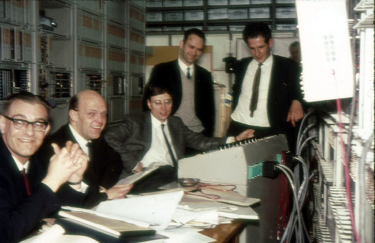
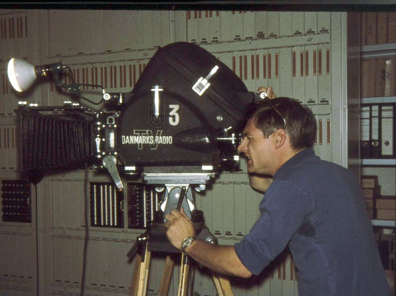