First-Hand:Arc Furnace Transformers (and me!): Difference between revisions
m (Text replace - "[[Category:Power,_energy_&_industry_application" to "[[Category:Power,_energy_&_industry_applications") |
m (Text replace - "Category:Power,_energy_&_industry_applicationss" to "[[Category:Power,_energy_&_industry_applications") |
||
| Line 184: | Line 184: | ||
<p></p> | <p></p> | ||
<p>[[Category:Power,_energy_& | <p>[[[[Category:Power,_energy_&_industry_applications|{{PAGENAME}}]] [[Category:Power_systems|{{PAGENAME}}]] [[Category:Transformers|{{PAGENAME}}]]</p> | ||
Revision as of 13:43, 13 November 2013
Arc Furnace Transformers (and me!)
Contributed by Thomas J. Blalock
While I was working at the former General Electric High Voltage Laboratory in Pittsfield, Massachusetts during the late 1960’s and early 1970’s, I became involved with an investigation of winding failures in electric arc furnace transformers that had been built at the G.E. Large Transformer plant in Pittsfield. Arc furnaces are most often used to melt steel scrap and refine it into useful metal.
This resulted in my being sent to several large arc furnace installations for the purpose of making oscillographic measurements of high voltage surges on the power systems supplying such transformers. It was suspected that a new type of vacuum switch that was being used in these installations was causing severe repetitive surges that were responsible for the winding failures. That proved to be correct.
Eventually, I became rather disgruntled with this project because of the need to spend so much time in these very noisy, dirty, and somewhat dangerous environments. Ironically, I now value those experiences because, about ten years ago, I became very interested in the history of the former Bethlehem Steel plant in Bethlehem, PA.
I am from the Lehigh Valley area originally, but I never had the opportunity to see any of the blast furnaces or open hearth furnaces in operation at Bethlehem. However, my experiences working around electric arc furnaces at least gave me a very good feel for what it is like to work in the world of “hot metal” !
By coincidence, my most valuable source of information regarding what actually went on in the Bethlehem plant is Don Young, who was a Foreman in the Electric Furnace Melt Shop at Bethlehem !
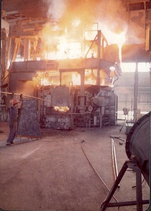
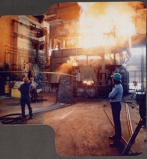
To say that the normal operation of large electric arc furnaces is “noisy” is a severe understatement. It is not possible to convey in words what it is like to be around one, especially during the initial meltdown period.
There is a past episode of the Discovery Channel program called “Dirty Jobs” which includes a segment in an electric furnace melt shop. The episode is titled “Steel Mill Worker” and first aired, I believe, sometime in 2008. It does convey a rather good feel for that working environment.
Historical Background
Sir Humphrey Davy demonstrated the heat-producing capabilities of an electric arc as early as 1810 (although he is most remembered for demonstrating the light-producing capabilities of an arc).
Thus, during the nineteenth century, several inventors experimented with the concept of an electric arc furnace. The most successful of these was Paul Heroult of France who developed a type of furnace that first appeared in the United States in the early twentieth century. Several of the furnaces that I became “friendly” with forty years ago were, in fact, Heroult furnaces. Some of the furnaces were built by the Lectromelt company who, I believe, purchased transformers for their furnaces from General Electric.
Since the source of heat in an electric arc furnace is the high-intensity arc itself, and not the combustion of some type of fuel, the atmosphere within the furnace is considered to be cleaner than that in other types of steel-refining furnaces.
Consequently, during the early twentieth century, the arc furnace became the preferred means of producing really quality types of steel, such as “tool steel” for cutting tools. Previously, “crucible steel” had been used for these applications. The closed refractory crucible allowed for a clean atmosphere, but the crucible process was severely limited as to the quantity of steel that could be produced.
The first successful method for refining large quantities of steel from blast furnace pig iron was the Bessemer converter in the mid-nineteenth century. This, however, was a rather uncontrollable exothermic process that yielded steel having widely varying metallurgical characteristics from batch to batch.
Thus, by the late nineteenth century, the open hearth furnace had become the preferred means of refining pig iron into steel because it was a much slower and more controllable process that produced steel of better quality and uniformity.
However, the open hearth furnace suffered from the disadvantage that the heat was produced by the combustion of fuel within the furnace. That required an oxidizing atmosphere within the furnace in order to support the combustion.
An oxidizing furnace atmosphere leads to the necessity for an oxidizing form of slag on top of the molten metal. The characteristics of the slag are crucial to the quality of the steel produced beneath it. In fact, a common saying among steel-refining furnace operators is that “the melter makes the slag and the slag makes the steel”!
The presence of an oxidizing slag limits the degree to which desirable alloys can be retained in the molten steel “bath” beneath it.
Since no fuel combustion takes place within an electric arc furnace, the furnace atmosphere can be “reducing” (oxygen poor). Thus, a reducing type of slag can be created and this leads to the ability to retain larger quantities of beneficial alloys in the molten steel bath. Therefore, higher quality steels can be produced.
Furnace Construction
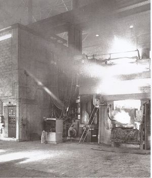
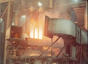
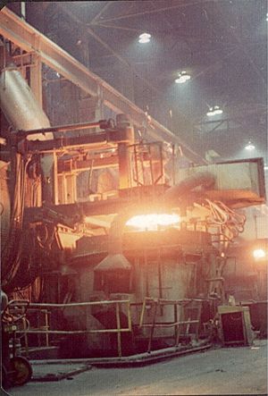
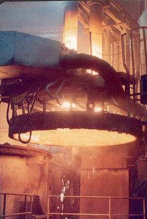
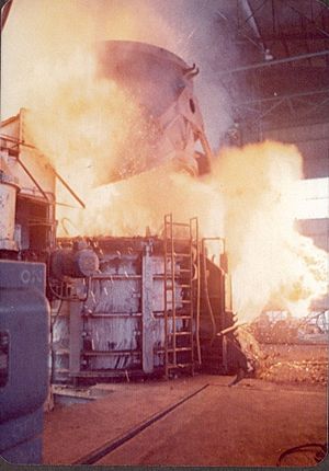
The arc furnaces that I was involved with were large, having capacities of from fifty to two hundred tons of molten metal per “melt” (or “heat”). The furnace itself consists of a cylindrical, refractory-lined steel vessel, perhaps as much as twenty or thirty feet in outside diameter.
The entire circular roof structure of the furnace is capable of being swung off to the side in order to allow the charging of cold scrap metal into the furnace by means of a huge clam shell type of bucket suspended from the hook of an overhead crane.
After charging, the roof structure would be swung back into place and secured. Three large cylindrical graphite electrodes (for three-phase operation) were suspended over three corresponding holes in the furnace roof in a triangular pattern. These were manufactured, by Union Carbide, in sections roughly 18 to 24 inches in diameter and about six feet in length (I am relying here on my sometimes unreliable memory).
These electrode sections had internal tapered threads at each end, and a threaded graphite connector was used to join them together. The electrodes were held by means of air-operated clamps at the ends of three long arms that were raised and lowered either manually or by means of automatic Amplidyne control. When an electrode became too short, a new section was suspended from an auxiliary hook on the overhead crane and “helpers” would have to work over the furnace (not operating, of course !) in order to screw the new section onto the top of the electrode. The clamp was then operated so as to slip the arm upwards, thus lengthening the electrode below the arm.
The travelling overhead cranes for the scrap buckets were on the order of 100 tons in capacity. At one location, I was told that a “test” for a good crane operator was his ability to crack the shell of a raw egg resting on the floor, using the crane hook, but not actually breaking the egg (according to Don Young, this is actually something of an industrial version of an “urban legend” !).
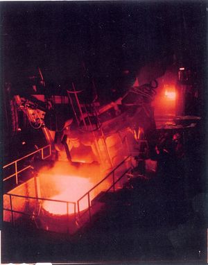
The entire furnace structure was raised above the Melt Shop floor to allow for the tapping of the molten metal into a refractory-lined ladle suspended from a crane on the far side of the furnace. The furnace itself was tilted in order to accomplish this.
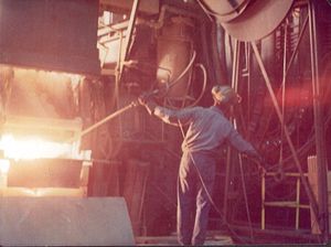
On the opposite side of the furnace, a water-cooled access door allowed the furnace operators (the “melter” and his helper) to pull excess slag out of the furnace using large steel hoes. The molten slag would fall down an opening in the operating floor to a pit beneath. Periodically, after the slag cooled down, it would be scooped up by a front-end loader and removed.
At another location I visited, the operators played a game during slagging. One would get set to shove the hoe into the furnace and pull slag out, and the other would look over the railing to the main building aisle below. If he saw any white collar types walking down the aisle, he would signal the operator when to pull the slag. The resulting shower of sparks below would burn little holes in the victims’ neckties and white shirts !
Furnace Transformers
I worked at five major arc furnace installations during this investigation:
- the General Motors Company’s Pontiac automobile plant in Pontiac, Michigan
- the Ford Motor Company’s “Michigan Casting Center” in Flat Rock, Michigan
- the John Deere tractor plant in East Moline, Illinois
- a U.S. Steel plant in Baytown, Texas (near Houston)
- a “Cosigua” Steel plant outside of Rio de Janeiro, Brazil
I have, in my files, details of the furnace transformers only for Pontiac and Baytown.
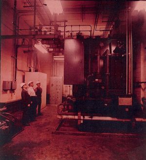
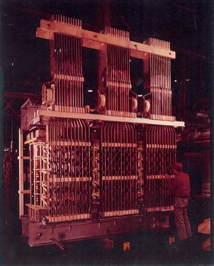
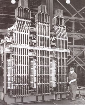
At all locations, the transformers were similar in design and construction. They were all oil-filled, water-cooled units and were always located inside concrete block vaults immediately adjacent to the furnace. The high current three-phase power was conveyed from the transformer secondary bus bars to the furnace electrodes by means of flexible air-cooled or water-cooled cables (to accommodate the raising and lowering of the electrode support arms).
The transformers were equipped with load tap changing (“LTC”) mechanisms in their high voltage (primary) windings, along with remotely-operated delta-wye switches to change the primary winding connections so as to obtain an even wider range of operating voltages. The secondary windings were always delta-connected so that the winding currents were less than the electrode currents by the factor of the square root of three.
At Pontiac, the transformers were rated at 20 MVA, and operated from a 41.6 kV power system. On the base (“neutral”) tap position, the rated secondary voltage was 365 volts, which provided a maximum electrode current of about 31,600 amps.
[In addition, these transformers were designed to withstand rather severe momentary overloads, which was normal during arc furnace operation.]
The arc furnaces at Baytown were huge, having 200 ton capacities (the furnaces at Pontiac were probably 50 ton capacity) and diameters of twenty-four feet.
Consequently, the Baytown transformers were rated at 75 MVA, and they operated from a 34.5 kV power system. The rated (neutral tap position) secondary voltage was 540 volts, corresponding to a maximum electrode current of about 80,000 amps !
At Pontiac, the control panel for a furnace was actually located out on the operating deck, not too far from the furnace (but the operators did have an adjacent office to temporarily escape the heat and noise of the furnace). At all of the other locations, I believe the control panels were inside an adjacent operating room with a window.
In general, the control panels contained:
- a standard SB-1 switch to control the breaker (actually, by this time, the vacuum switch) which energized the primary of the transformer
- a tap-changing switch and indicating lights to select the transformer tap
- three ammeters to indicate the three electrode currents
- a switchable voltmeter to indicate the electrode voltages
- three switches plus a master switch to control the raising and lowering of the electrode supporting arms in manual mode
- three electrode current adjusting rheostats, connected in the field circuits of the three Amplidyne control generators for automatic operation
- a kilowatt-hour meter to record the total energy used for each heat
- a totalizing three-phase wattmeter (sometimes called a “heat meter” by the operators) which served to indicate the rate of heat input
In addition, there were three incandescent lamps at the top of the control panel.
These were connected to the secondaries of three step-down “pot” transformers whose primaries were connected to the electrodes in a grounded wye configuration.
As I recall from Pontiac, after charging the furnace with a load of cold scrap metal, and securing the roof structure, the operator would manually lower the electrodes until they were close to the scrap. Then, he would lower one electrode until it touched the (grounded) scrap, which would be indicated by its lamp on the control panel going dark. He would then lower one or both of the other two electrodes until an initial arc was struck. When a three-phase arc was established (as indicated by all three lamps flickering wildly), he would then switch over to automatic operation.
At that point, the Amplidynes would take over control of the raising and lowering of the electrodes so as to maintain relatively constant and balanced current flows. The motor-driven Amplidyne generators powered D.C. motors that actually moved the electrode arms. C.T.’s in the secondary bus bars from the furnace transformer provided current signals that, through electronic circuitry, controlled the fields of the Amplidynes.
After the charge had melted down into a molten pool, the operation of the furnace settled down to just a steady loud roar. The process of converting the raw scrap into refined metal took a few hours. In spite of the intense heat in the furnace, the helper would sometimes have to use an oxy-acetylene torch or an oxygen lance to burn away solidified metal at the tap hole when it came time to tap the furnace into the ladle.
One time, I noticed an operator tucking an aluminum foil packet into a nook of the furnace structure during a melt. He noticed me watching him do this, and so he then explained “that’s my lunch – fried chicken” !
Once we became somewhat accustomed to the heat and noise of this environment, the whole process became extremely fascinating to watch. We even accepted the fact that we would occasionally have to step over blobs of semi-molten metal that had leaked out around the furnace door. I picked up one of these (after it had cooled !) to keep as a souvenir, and I still have it.
Arc Furnace Operation
The melting of the charge of steel scrap would begin with the furnace transformer on a lower tap position. This resulted in a (slightly) less ferocious arc, which was necessary in order to protect the refractory roof of the furnace from the intense heat of the arc (around 6000 degrees F) until the electrodes were able to burrow into the charge somewhat.
Regardless, this was still the most awe-inspiring (frightening ?) portion of the melt. The magnetic forces created by the electrode currents would throw smaller pieces of scrap around the inside of the furnace creating a rather disconcerting racket. This was accompanied by the loud “bellows” and bright blue-white flashes of the not yet stable 60-Hertz arcs, and showers of sparks thrown upwards from the electrode openings.
In fact, one reference on this subject claims that if the phase rotation of the three electrode currents is not correct, this can actually cause the resulting magnetic forces to unscrew the electrode sections !
Eventually, as the arc melts down the scrap and a molten pool of metal is formed, the transformer tap position can be raised so as to increase the arc current and hasten the melting process. The power input to the furnace (which, of course, is converted into heat) is a function of the arc currents and the lengths of the arcs. The latter is controlled by the Amplidyne-driven electrode arm motors.
Interestingly, at Pontiac and Flat Rock (Ford), the steel scrap was actually being refined back into cast iron for use in the foundry to cast engines blocks and such. Cast iron has a higher carbon content than steel, so additional carbon sometimes had to be added to the molten metal bath in the furnace. One method to accomplish this was to simply lower the graphite electrodes into the bath (with the power off) for awhile and allow the bath to dissolve some carbon from them.
The most unusual sight at Pontiac was piles of green tree saplings lying on the operating deck. As best as I can recall, these were used as “rabbles” to stir the bath when necessary. Being green, they would not burn off as rapidly. As they did burn, however, they simply added a bit more desirable carbon to the molten metal.
Periodically, samples would be taken using a long-handled cup and these would be sent to an adjacent laboratory for analysis. The resulting report might instruct the operator to increase or decrease the carbon content, or to add so many shovels of alloying additives (possibly materials such as manganese or silicon). Another additive used was fluorspar (called simply “spar” by the operators) which served to increase the fluidity of the slag.
If the carbon content actually became excessive, an oxygen lance (really just a long length of black steel pipe through which pure oxygen flowed) was inserted through the partially open furnace door to burn off the excess carbon. The pipe was gradually fed into the furnace as the end melted off, the operator holding the pipe being protected by a moveable heat shield.
The John Deere arc furnace melt shop was probably producing some cast iron as well, but also could have been supplying metal for steel castings.
The Baytown (U.S. Steel) plant was quite new when we were there in the early 1970’s. It produced steel plate from slabs and, eventually, large diameter steel pipe as well. In fact, the 48-inch diameter Alaskan oil pipeline sections were fabricated at Baytown. This huge plant, however, was largely closed down by 1986, the result of problems that plagued the entire United States steel industry.
We encountered an atmosphere of secrecy at Baytown which we did not really understand at the time. In fact, I was the victim of industrial espionage because some documents were taken from my briefcase by a U.S. Steel engineer.
Much later, I learned that the reason for this was the fact that they were, at that time, using the first large scale continuous caster in the company. This device eliminated the traditional time-consuming steps of teeming the molten metal into ingot moulds, and then rolling the ingots in a blooming mill to produce blooms that would subsequently be rolled into slabs. Molten metal was teemed directly into the top of the continuous caster and a slab appeared at the bottom.
Eventually, we were allowed to watch the continuous caster in operation after they realized that our lack of knowledge about steel production techniques meant that we were no threat to their security.
The Cosigua plant in Brazil was also quite new when we were there (a year after Baytown). This included a rod mill which we were able to observe at one point. A white hot billet was fed into the first stand of the rolling mill complex and each subsequent stand through which it passed reduced its diameter and increased its speed of travel. By the time it became rod-sized, it was really moving, and was still red hot !
If the speed of one roll stand was slightly low, the fast-moving steel rod would quickly form red hot coils behind the stand. This happened while we were watching and the operator rapidly put into operation a flying shear which then chopped the coils into less dangerous short pieces. Even so, some damage resulted and had to be repaired by the millwrights. I don’t know if this event was due to the newness of the mill, or whether this still happens occasionally in established rod mills.
Arc Furnaces Today
Prior to World War I, the Bethlehem Steel plant installed a “Girod” 10-ton capacity arc furnace that operated on direct current power (in that era, D.C. power was commonly available for operating motors in large industrial plants). One advantage of a D.C. arc furnace is that only one electrode is required, instead of three. A metallic furnace bottom serves as the return electrode.
According to Don Young, the steel plant at Steelton, PA (south of Harrisburg), which once was owned by the Bethlehem Steel Corporation, now has operating a 150-ton D.C. arc furnace of Japanese make. Today, the use of D.C. furnaces is facilitated by the availability of high power solid-state rectifiers to efficiently convert the available A.C. power to D.C.
Regardless, a great many conventional three-phase arc furnaces are in use today. I suppose it is possible that some of the furnaces I was exposed to forty years ago could still be operating (having had many, many re-linings, of course !).
Arc furnaces are of even more importance in the modern world since, after all, they are really very large recycling machines.
As far as furnace transformers are concerned, a cursory Internet search seems to indicate that the sources of these today are countries such as China and India.
References
Electric Furnace Steelmaking - Volumes I & II (by editorial committee), Interscience Publishers (John Wiley & Sons), New York, 1962
Electric Melting Practice by A.G.E. Robiette, Griffin and Company, London, 1972
[[
