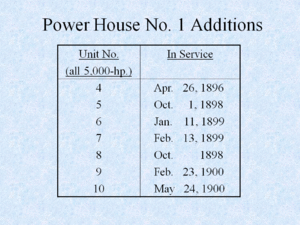
Early Electrification of Buffalo
The Beginning of Central Station Service
[NOTE: This is Part 1 of a fourteen part series of articles first developed as a PowerPoint presentation by Craig A. Woodworth, IEEE Life Member (a.k.a Cawoody), for a joint meeting of the Buffalo Section IEEE and the Buffalo & Erie County Historical Society on April 14, 2004.]
See also:
Early Electrification of Buffalo: Adams Station - Electric Development (Part 5) Early Electrification of Buffalo: Niagara to Buffalo Transmission Lines (Part 6) Early Electrification of Buffalo: Electricity Distribution Within Buffalo (Part 7) Early Electrification of Buffalo: Early Power Company Interconnections (Part 8) Early Electrification of Buffalo: Niagara Falls Water Diversion Limitations Result in Steam Station Construction (Part 9) Early Electrification of Buffalo: Hydroelectric Reorganization to Increase Efficiency (Part 10) Early Electrification of Buffalo: Types of Electric Service available in Buffalo (Part 11) Early Electrification of Buffalo: 60-Hz Replaces 25-Hz (Part 12) Early Electrification of Buffalo: Contributions of Five AIEE Presidents (Part 13) Early Electrification of Buffalo: 1925 Residential Electric Bill (Part 14)
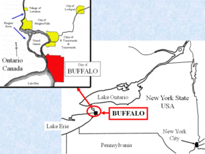
The City of Buffalo is located in western New York State at the junction of Lake Erie and the Niagara River. It is approximately ten miles north-to-south and six miles east-to-west with an area of 42 square miles. Niagara Falls is located 20 miles north of the city [Fig. 1.1]. In 1900 Buffalo, with a large commercial and industrial base, was the eighth largest city in the United States.
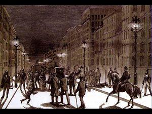
Buffalo, the Queen City of the Lakes, was an up-to-date city at the end of the 19th century and electric lights were in the forefront. "I went to the city to see the great sights and there I saw what they call ‘lectric lights. Now I think I know what I’m talking about ‘cuse they put them up in bottles and you can’t blow them out.”i [Fig. 1.2]
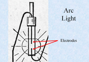
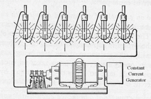
The earliest electric lights were arc lights.ii The electric discharge between two carbon or other type electrodes gave a brilliant light suitable for lighting streets, large stores and halls but not homes [Fig. 1.3].iii Arc lights for street lighting were usually on constant-current series circuits [Fig. 1.4].
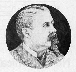
Charles Brush was a pioneer in the development of arc lights [Fig. 1.5].iv In July 1881 the Brush
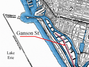
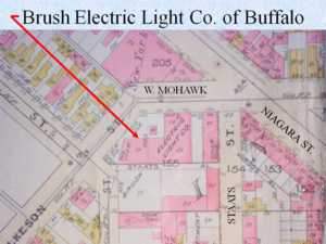
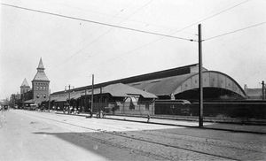
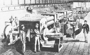
Electric Light Company of Buffalo installed the first electric plant in Buffalo on Ganson Street along the City’s waterfront [Fig. 1.6].v A 30-hp steam engine driving a generator with a capacity of forty 2,000-candlepower arc lamps supplied twelve carbon arc lights extending a mile along the street. In August a second station was built in the New York Central Railroad’s Chicago St. roundhouse supplying thirteen arc lights in the Exchange Street Depot [Fig. 1.7]. A third station was added in 1882 at Wilkeson and Mohawk Streets near the present City
Hall to extend arc lighting service to many other streets, churches, public meeting places, hotels and other business places [Fig. 1.8]. The Buffalo Electric Light and Power Company also had its machines installed at Brush’s Wilkeson Street Station. This location was used as an electric company station for 120 years.
In October 1881 the United States Electric Lighting Company gave a lighting exhibition in a factory building at 296 Washington Street and installed ten lamps in the J. N. Adams store in November. In 1883 this company placed two direct current machines in Brush’s Wilkeson Street Station for the first incandescent lamps
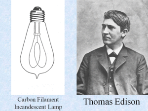
installed in Buffalo.vi Edison had developed the first practical electric incandescent lamp four years earlier [Fig. 1.9].
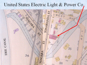
Other companies joined the lighting rush. In 1885, the United States Electric Light and Power Company of Buffalo had a plant for arc lighting in the Black Rock section of the City [Fig. 1.10].vii In 1887, the Thomson-Houston Light and Power Company of Buffalo had a plant for arc lighting located on Effner Street and later moved downtown to 40 Court Street.viii
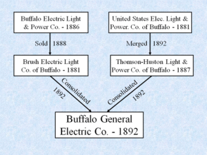
The Buffalo General Electric Company was formed August 1, 1892 as a consolidation of the Brush Electric Light Company of Buffalo and the Thomson-Houston Electric Light and Power Company of Buffalo, which had combined with two of the previously mentioned companies [Fig. 1.11].ix Next: Part 2 of 14: Early Electrification of Buffalo: Advent of Alternating Current
References
i. A ditty repeated in the author’s youth by his father Harry Woodworth (1893-1970).
ii. “Engineering the Electric Century: Arc lights create first surge of demand for electricity on large scale,” Electrical World, March 15, 1973: 30-31.
iii. Alfred Morgan, First Electrical Book for Boys (New York: Charles Scribner’s Sons, 1940), 128.
iv. “Giants of the Electric Century 1874-1974: Charles Francis Brush, Pioneer of electric arc lighting” Electrical World, May 1, 1973: 35.
v. Niagara Mohawk Power Corporation. The Niagara Mohawk Story (1823-1983): A Reference Manual of 160 Years of Niagara Mohawk Power Corporation and its Predecessor and Associated Companies, 2d ed. (Niagara Mohawk Power Corporation, Syracuse, NY, 1983, mimeographed), 67-69.
vi. Niagara Mohawk Story, 73.
vii. Niagara Mohawk Story, 71.
viii. Niagara Mohawk Story, 71.
ix. Niagara Mohawk Story, 75.
This article is Part 2 of a 14 Part series.
Previous: Part 1 of 14: Early Electrification of Buffalo: The Beginning of Central Station Service
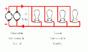
In September 1882, the Pearl Street Station of the Edison Electric Illuminating Company in New York City went into operation serving 85 customers with some 400 incandescent lamps [Fig. 2.1]. This central station system, which was designed to serve an area approximately one-mile square, consisted of constant voltage direct current generators connected in parallel serving radial circuits with lamps connected in parallel.i 110 volts was selected on the basis of economics with copper being the
largest cost [Fig. 2.2].ii It is remarkable that in the last century the voltage has been adjusted upward only slightly to today’s standard of 120 volts.
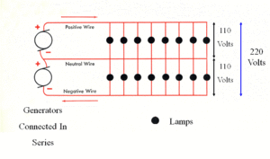
The next important development came less than one year later in July 1883 when a three-wire system went into operation in Sunbury, Pennsylvania with a 62 1/2 percent saving in copper compared to the New York system [Fig. 2.3].iii To serve the same
load with two generators connected in series, the current is cut in half. The neutral current is zero with equal loads on both generators. Direct current systems had three major disadvantages:
- Generation had to be located reasonably close to the load due to the voltage drop, which required large size wire.
- Generation had to be at utilization voltage.
- Low utilization voltage meant high currents and high currents meant high losses in the distribution lines.
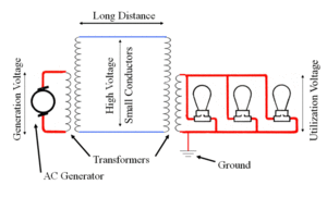
The adoption of alternating current systems overcame these disadvantages. While Edison was improving the dc system, others were developing the alternating current system, which, by using transformers, could raise the generation voltage and utilize small conductors for distribution, then lower the voltage for loads remote from the generation [Fig. 2.4]. The safety problem of a transformer insulation breakdown applying high-voltage to the secondary was solved by the simple but effective expedient of grounding the transformer secondary winding.iv
Advent of Alternating Current
The first alternating current central station to operate commercially in the United States was placed in service in Buffalo on November 30, 1886 only four years after Edison’s Pearl Street Station. It was a Westinghouse 400 lamp single-phase (or two-wire) system with a primary of 1000 volts. The generator was located in the Brush Electric Light plant at Wilkeson and Mohawk Streets. One customer was the Adam, Meldrum & Anderson department store on downtown Main Street, now the site of the Main Place Mall.v
The following year in Montpelier, Vermont an ac system replaced a dc system and
the value of the copper salvaged was enough to cover the cost of conversion.vi Also in 1887 a French syndicate was gaining a monopoly on the world’s copper supply and forced up the price nearly 70 percent.vii This made ac systems, which used smaller conductors, more attractive. And you thought that technology changed fast only in recent years! How’s your five-year-old computer doing?
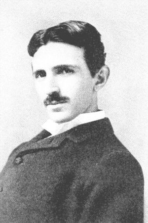
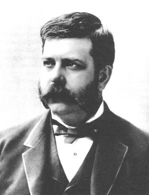
Early ac systems had one major disadvantage: there was no commercially available ac motor. This shortcoming was solved in fairly short order. On May 1, 1888 Nikola Tesla [Fig. 2.5] was issued his first set of patents for a comprehensive system of generators, transformers, synchronous motors and induction motors for the transmission and utilization of two or more alternating currents -- what came to be known as the polyphase system. Two months later, George Westinghouse [Fig. 2.6] acquired the patent rights and Tesla’s services.
During development of the polyphase motor it was found necessary to reduce the alternations from 133 Hz. or cycles per second (the more or less standard frequency for the early single-phase systems) to 60 Hz. This remains the standard North American frequency. Tesla also developed several “split phase” designs for motors for the single-phase systems.
References
i. “Engineering the Electric Century: Pearl Street Station inaugurates an era,” Electrical World, May 15, 1973: 33.
ii. Christopher S. Derganc, “Thomas Edison and His Electric Lighting System,” IEEE Spectrum, February 1979:56.
iii. “Engineering: Pearl Street,” 34.
iv. “Engineering the Electric Century: As dc distribution limits loomed, higher voltages of ac systems promised a solution,” Electrical World, June 15, 1973: 74.
v. “Niagara Mohawk Story,” 69. “dc distribution limits,” 75. Charles A. Ruch, “A Young Westinghouse is Challenged,” Westinghouse Retirees’ News, March 1993:6. Edward Dean Adams, Niagara Power: History of the Niagara Falls Power Company 1886-1918, 2 vols., (Niagara Falls, NY: Privately printed for The Niagara Falls Power Company MCMXVIII, 1927), 2:170.
vi. “dc distribution limits,” 75.
vii. “The Copper Ring and the Senate Tariff Bill,” New York Times, 30 Nov 1888.
Developing a Renewable Energy Source
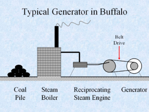
The early Buffalo systems probably all had a common arrangement: a coal fired boiler with a reciprocating steam engine of a couple hundred horsepower maximum, belt connected to a generator that served an area of about a square mile [Fig. 3.1]. What other source of energy was available?
The greatest source of renewable energy on the Niagara Frontier is at Niagara Falls. The energy of the falling water has been estimated at six million horsepower.
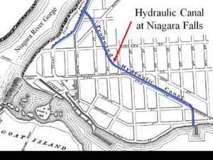
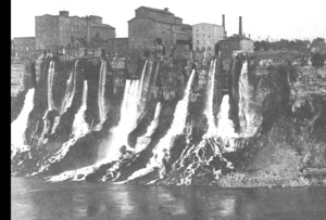
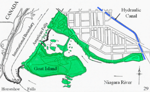
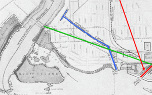
The story of the development of the Hydraulic Canal to provide waterpower for industries at the brink of the Niagara gorge and its purchase by the Schoellkopf interests in 1877 will not be repeated here [Fig. 3.2]. Note that the industries used only a portion of the available head of water [Fig 3.3].
In 1885 the State of New York acquired all the land for about a mile upstream and a quarter-mile downstream from the American
Falls plus all the islands for a State park [Figure 3.4]. This removed all the readily available waterpower sites except for the Hydraulic Canal. How could more of this renewable energy be utilized?
In February 1886 Thomas Evershed, a division engineer on the Erie Canal, developed a plan to construct a series of canals from the Niagara River and sell mill sites on both sides of the canals.
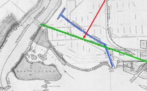
Water would be drawn from a canal, run through a waterwheel and discharged into a tailrace tunnel that would run into the Gorge [Fig. 3.5]. The profile shows the canals and wheel pits [Fiig. 3.6]. A total of 238 mills of 500 hp each could be developed.i This would be 119,000 hp or more than the total of all the developed hydropower in eastern New York and New England combined.ii In June 1886 the Niagara River Hydraulic Tunnel, Power & Sewer Co. was organized to pursue the Evershed plan.iii It was chartered by the State of New York and later authorized to take water from the Niagara River sufficient to produce 200,000 hp.iv
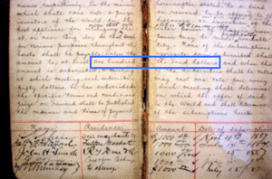
The Prospectus stated “It is conceded by leading practical electricians that it would be entirely practicable now to light the City of Buffalo (distance 20 miles) with power furnished by Niagara Falls,… An application has already been received from a manufacturer in Birmingham, England, for an opportunity to test his apparatus for conveying power by means of compressed air.”v Various attempts to finance the project proved futile. In July 1887 a number of enterprising citizens of Buffalo provided a cash prize of $100,000 for a practical method of using Niagara power in Buffalo [Fig. 3.7].vi None of the projects submitted merited the prize.
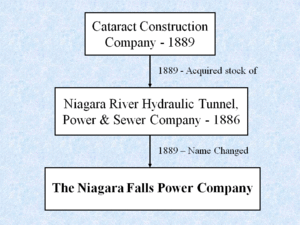
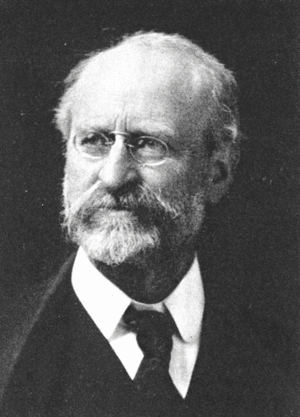
In 1889 the ‘Tunnel” company, through attorney William Rankine, got the attention of J. P. Morgan and Edward Dean Adams, a New York City attorney and investment banker [Fig. 3.8]. Adams consulted the renowned mechanical engineer Dr. Coleman Sellers [Fig. 3.9]. Sellers reviewed the Evershed prospectus and informed Adams that the plan was financially feasible.vii In December 1889 a syndicate of financiers organized The Cataract Construction Company with Adams as president. The Cataract company acquired all the stock of the “Tunnel” company and would act as its business and financial agent.viii
The Cataract company was designed to represent all the money subscribers to the enterprise and to be the means of their profiting by its contract with the “Tunnel” company for the design and construction of the project. This speculative venture was expected to be slow in developing. The organization of capitalists and engineers became an association of adventurers and pioneers.ix In late 1889 the “Tunnel” company’s name was changed to The Niagara Falls Power Company [Fig. 3.10].x
Difficulties with the Evershed plan soon appeared. The construction of over five miles of tunnel and 238 wheel-pits practically all by rock excavation in hard limestone indicated the economy of fewer wheel-pits and shorter tunnels and inlet-canals.xi Questions arose:xii
1. Was the old plan of placing a mill over or near its own water wheel adaptable to a project of unprecedented magnitude, or could power produced at one place be supplied to several customers?
2. Could power be distributed locally or transmitted a considerable distance by shafts or belts or wire ropes, by compressed air or water pressure, or by electricity?
3. Could Buffalo, with a population of 255,000, compared to 5,000 in Niagara Falls, be reached by any practical method? Edison was asked and replied “No difficulty transferring unlimited power.” He proposed connecting several dc generators in series at Niagara Falls to obtain 6,000 volts, utilizing underground cable across Grand Island and connecting several dc motors in series in Buffalo.xiii Westinghouse advocated compressed air.xiv Compressed air had an advantage in that it could be used in place of steam in many existing steam engines.xv
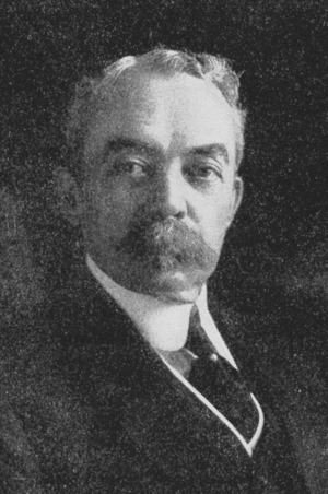
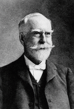
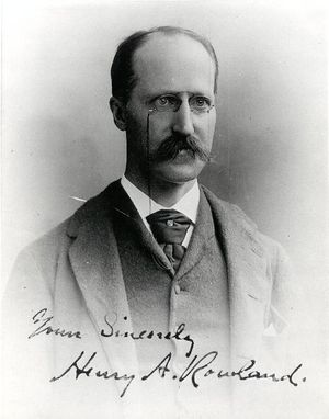
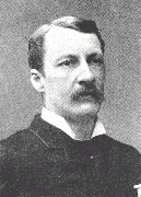
Consultants were engaged including Clemens Herschel, an hydraulic engineer who had extensive experience on American waterpower projects [Fig. 3.11] and Professor Henry Rowland, a physicist from Johns Hopkins University who was to determine if the project was economically feasible [Fig. 3.12]. Professor Rowland reported “.. the practical and commercial problem is of a different nature than the scientific one and may be stated thus: at what distance from cheap water-power can such power, transmitted electrically, compete with steam in cost and certainty of operation?”xvi New methods were called for; power was to be produced on an unprecedented scale. Nothing in existence was adequate to accomplish these results.xvii
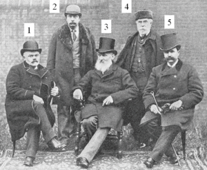
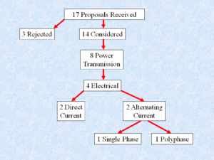
In the midst of all this doubt, the Construction company did what any self-respecting organization does; in July 1890 they formed a committee. But what a committee! It was named the International Niagara Commission and consisted of E. Mascart (Professor, College of France), William Unwin (Professor, Central Institute London, England), Sir William Thomson (later Lord Kelvin; University of Glasgow, Scotland), Dr. Coleman Sellers (Professor, Stevens Institute and Franklin Institute, United States), and Theodore Turrettini (President, City of Geneva, Switzerland and a waterpower engineer) [Fig. 3.13].xviii The Commission investigated the state of the art of power transmission in the United States and Europe and also sent out invitations offering a monetary prize for plans for hydraulic development and power transmission and distribution including 50,000 hp to Buffalo.xix Competitors from six countries submitted seventeen proposals. Three were rejected as irregular.xx Of the eight projects presented for power transmission, only four proposed electrical methods [Fig. 3.14]. Two advocated direct current and two alternating current; one single phase and one polyphase.xxi Westinghouse refused to submit a proposal remarking
“These people are trying to secure $100,000 worth of information by offering prizes, the largest of which is $3,000. When they are ready to do business, we will show them how to do it.”xxii Prizes were awarded in early 1891. No first prize was awarded for a combined project for hydraulic development and distribution. In the opinion of the Commission, no project could be recommended for adoption without considerable modification.xxiii The Commission’s report takes up 53 pages in Volume I of Edward Dean Adams’ book ‘Niagara Power’ and provides interesting reading.xxiv
References
i. Adams, Niagara Power, 1:116.
ii. Ibid., 141.
iii. Ibid., 120.
iv. Ibid., 119.
v. Ibid., 122.
vi. Ibid., 94.
vii. Jill Jonnes, Empires of Light: Edison, Tesla, Westinghouse and the Race to Electrify the World (New York: Random House, 2003), 282-283.
viii. Adams, Niagara Power, 1:233, 292.
ix. Ibid., 292, 297.
x. Ibid., 132.
xi. Ibid., 143.
xii Ibid., 142.
xiii Ibid., 144-147. Adams, Niagara Power, 2:171.
xiv. Adams, Niagara Power, 2: 221.
xv. Ibid., 203.
xvi. Adams, Niagara Power, 1:152-156.
xvii. Ibid., 163.
xviii. Ibid., 173.
xix. Ibid., 395.
xx. Ibid., 187.
xxi. Adams, Niagara Power, 2:219.
xxii. Adams, Niagara Power, 1:363.
xxiii. Ibid., 187.
xxiv. Ibid., 413.
Niagara Falls Hydraulic Development - Adams Station
‘Fast tracking’ a building where the foundation is completed before the design of the upper floors is complete is a common current practice. This principle was applied to construction of the Adams Station. Because a tailrace tunnel was common to any project, a contract was awarded in September 1890. Construction of the 1-1/4 mile long tunnel
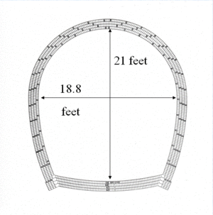
commenced in October 1890 and was completed in December 1892 [Fig. 4.1]. A horseshoe shape 21 feet high and 18.8 feet wide
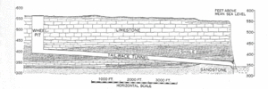
was selected [Fig. 4.2]. During construction through the weak Rochester shale strata, it became necessary to line the tunnel using a total of sixteen million bricks in four courses set in Portland cement. A profile of the tunnel shows the extent of the shale [Fig. 4.3].
By July 1891 plans had reached the following stage:i
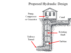
1. Hydraulic system consisting of a single inlet canal, the shortest possible tailrace tunnel, and a central station for power development. The turbine units should be large and mounted at the bottom of the wheel pit. Their complementary machines, whether pumps, compressors or generators should be mounted on the top of the same rotating shaft so as to constitute a unit of power
.[Fig. 4.4]
2. Local distribution of power by direct current of electricity.
3. Transmission of power to Buffalo by compressed air.
The inlet canal was started in August 1891 and completed in October 1892 [Figure 4.5].
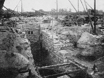
The 20 feet wide and 182 feet deep stone masonry wheel pit was started in late 1891 and completed in January 1894 [Fig. 4.6].ii
The state of the art of electric power transmission in the early 1890’s was as follows:iii
1. 1890 - Willamette Falls to Portland, Oregon - 4,000 volts ac single-phase 12 miles for lighting.
2. 1891 - Telluride, Colorado - 3,000 volts ac single-phase three miles supplying a 100-hp synchronous motor for operating an ore crushing plant.
3. 1891 - Lauffen to Frankfurt, Germany - Experimental 30,000 volt three-phase line 108 miles for 300 hp for the Frankfort Exposition. Overall efficiency 77 percent.
In early autumn of 1891 it became evident that alternating current could be safely and economically controlled for the transmission of power more than five times the distance from Niagara to Buffalo. From this period, all serious attention was concentrated upon electrical installations; generators, transformers, transmission lines, motors, and power and light distribution.iv
In December 1891 an invitation to submit proposals for generation of electrical energy for local lighting and power purposes was sent to three United States and three Swiss electrical equipment designers and manufacturers. The invitation did not mention direct current, alternating current or voltage. It took a year until all proposals were received.v
In 1892 Professor George Forbes, an electrical engineer from England, was hired as a consultant [Fig. 4.7]. He had submitted the polyphase alternating current electrical proposal to the International Niagara Commission contest.vi Horsepower and speed were determined by consultation with the hydraulic turbine and electrical equipment manufacturers.vii The contemplation of the use of electricity from hydraulic units of 5000 hp in a plant, which would ultimately aggregate 100,000 hp, required imagination, optimism and confidence. 100,000 hp approximated the output of all the electric lighting stations in the United States.viii
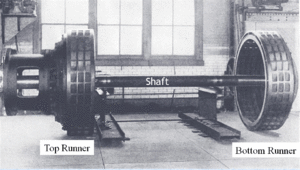
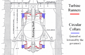
In July 1892 a contract was awarded to Faesch & Piccard of Geneva, Switzerland for complete working drawings of a 5000-hp 250-revolutions-per-minute hydraulic turbine including the governor.ix The turbines far exceeded in power and speed any then in existence.x Transportation costs and import duties made domestic manufacture economical.xi In November 1892 a contract was awarded to I. P. Morris of Philadelphia for two turbines. A third was added in 1893.xii The turbines were double runner Fourneyron type with outward discharge directly into the wheel
pit [Fig. 4.8 & 4.9]. There were no draft tubes. Water pressure on the top runner supported a large portion of the weight of the revolving parts of the units, the remainder being carried by a collar thrust bearing.xiii The
mechanical governors, which were made in Switzerland by Faesch & Piccard, regulated the flow of water by raising or lowering a circular collar placed outside the turbine discharge.xiv The variation in speed would not exceed two percent normally or four percent with a 25 percent variation in load.xv This speed variation would be totally unacceptable today.
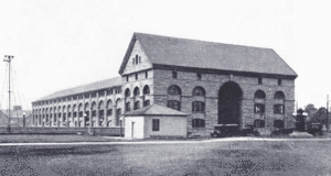
The New York City architectural firm of McKim, Mead & White was engaged to design the limestone powerhouse [Fig. 4.10].xvi
References
i. Adams, Niagara Power, 1:164, 2:106.
ii. Adams, Niagara Power, 2:38, 48.
iii. Ibid., 174, 179. “Engineering the Electric Century: Transmission by ac gives impetus to hydro,” Electrical World, September 15, 1973: 72.
iv. Adams, Niagara Power, 2:106, 222.
v. Ibid., 223.
vi. Ibid., 356.
vii. Ibid., 85.
viii. Ibid., 181.
ix. Ibid., 433.
x. Ibid., 85.
xi. Ibid., 104.
xii. Ibid., 113.
xiii. Ibid., 439.
xiv. Ibid., 107.
xv. Ibid., 113.
xvi. Ibid., 66.
Adams Station - Electric Development
It is interesting that in late 1892 the turbines were ordered four months before all the proposals were received for generators for local lighting and power. This was the era of the ‘Battle of the Currents’ with Edison as the leading proponent of direct current and with Westinghouse and others promoting alternating current. When the first execution by electricity took place in 1890 in New York State’s Auburn Prison, an ac electric chair was used. Dc proponents said the condemned murderer had been “Westinghoused.”i
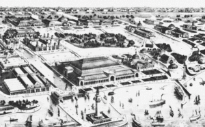
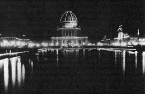
The opportunity for a large scale demonstration of the alternating current system to dispel fears about the system’s high voltages and display its versatility came in the spring of 1892 when bids were taken to light the grounds of the Columbian Exposition to be held in Chicago in 1893 [Fig. 5.1]. Westinghouse astounded everyone by bidding about one-third of the bid submitted by the recently formed General Electric Company. GE held the Edison incandescent lamp patents, a seeming crippling handicap.
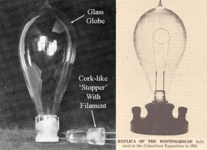
However, Westinghouse owned the rights to an 1880 Sawyer-Man patent for a two-piece lamp, which had a glass globe and a cork-like ground glass stopper that didn’t infringe on the Edison patents [Fig. 5.2].
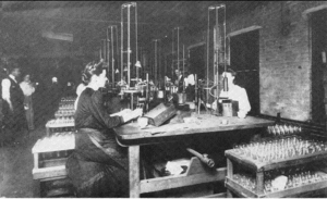
In less than a year Westinghouse built a factory and produced a quarter million of these “stopper” lamps [Fig. 5.3]. The Exhibition used more electricity than the whole City of Chicago.
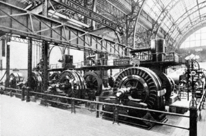
The central-station plant that supplied the fair consisted of twelve two-phase generators rated 750 kW, 60 Hz, 2000 to 2300 volts, belt driven or direct driven by five reciprocating steam engines [Fig. 5.4]. The Westinghouse exhibit in Machinery Hall was the largest plant of the Tesla polyphase system operating at that time. In addition to the lighting plant, there was an exhibit of a complete polyphase system which showed power could be transmitted great distances, and then be utilized for various purposes.
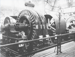
Taking power from the 60-Hz fair circuits was a 500-hp motor that drove a two-phase 500-hp, 30-Hz, 400-volt generator Fig. 5.5]. This powered a 400 volt-to-10,000 volt step-up transformer, a short ‘transmission’ line, and a step-down transformer which ran induction motors, a synchronous motor
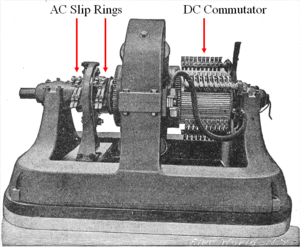
plus a rotary converter for changing alternating current to direct current.ii The converter had a rotating armature with four slip rings for the two-phase ac and a commutator for the dc [Fig 5.6].iii The Westinghouse polyphase exhibit was a big attraction when the Columbian Exhibition opened in the spring of 1893. Wooden models of the hydraulic turbines and governors under construction for Niagara Falls were also exhibited.iv
Representatives of the Cataract company had attended demonstrations of polyphase equipment at the Westinghouse factory and on May 6, 1893 adopted polyphase alternating current for both local use and transmission to Buffalo.v Complications of the electrical design delayed awarding a contract for the generators. Transportation costs, import duties and patent questions removed the foreign manufacturers from competition.vi The generator designs submitted in March 1893 by Westinghouse and General Electric did not fulfill the conditions imposed by the turbine designers for angular momentum and limited weight.
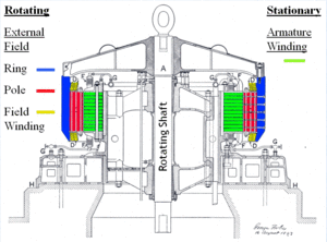
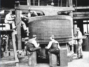
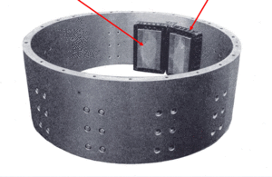
On August 10, 1893 new bids were requested based on a design by Professor Forbes of the Cataract company for a 20,000 volt two-phase generator with an external rotating field of the “umbrella” type whereas a rotating armature was standard practice [Fig. 5.8].vii Figure 5.9 shows the rotating field ring with the field poles and field windings. The armature winding was stationary. Westinghouse proposed two-phase; General Electric recommended three-phase.viii Two-phase four-wire was selected because it was expected that much of the local load would be single-phase.ix Next the frequency had to be selected. Hydraulic turbines had been ordered with a speed of 250 rpm. The frequencies possible at 250 rpm were: 16 2/3-Hz with 8 poles on the rotating field; 25-Hz with 12 poles; 33 1/3-Hz with 16 poles and 41 2/3- Hz with 20 poles. Low frequencies were preferred for large motors and rotary converters. Professor Forbes preferred 16 2/3- Hz for the commutating type ac motors then in use. Higher frequencies were more suitable for incandescent and arc lights. Tests had shown that at 25 Hz incandescent lamps did not show objectionable flickering. Westinghouse had adopted 60 Hz for lighting and 30 Hz for power and refused to guarantee efficiency at less than 30 Hz. General Electric recommended 41 2/3 Hz. Following a dinner meeting in October in New York City with Westinghouse representatives, President Adams of the Cataract Company asked Westinghouse’s chief electrical engineer if they could build and guarantee a 25-Hz generator. Later in October revised proposals were received from Westinghouse and General Electric. Changes had to be made in the Forbes design. A 20,000-volt oil-cooled armature was not practical.x On October 26 a contract was placed with Westinghouse for three 5000-hp, 25-Hz, 2200 volt, two-phase, four-wire generators.
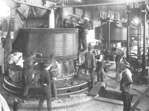
xi Figure 5.10 shows a view of a generator armature at the Westinghouse factory. The armature conductors were insulated with mica, which was a fortunate choice because thermocouple tests in later years showed temperatures as high as 225C.
Figure 5.9 shows a nickel steel field ring with two of the twelve poles and coils. Adams ‘Niagara Power’ book contains many pages detailing the design, manufacture, testing
and installation of these pioneering generators along with the auxiliary electrical apparatus including exciters, measuring instruments and switching devices [Fig 5.11]. The testing of the first machine at the Westinghouse plant in Pittsburgh was probably the origin of the cardinal rule “Never place a short circuit on a piece of rotating machinery.” This was done during testing with great disturbance to the windings.
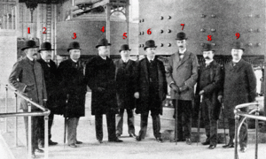
xii The first turbo-generator was successfully tested and operated in April 1895 [Fig 12].xiii The tall gentleman, No. 7, is John Jacob Astor and No. 8 is Edward Dean Adams, President. Schallenberger of Westinghouse designed a new type of switchboard indicating and integrating meters. On August 26, two-phase four-wire 2200 volts was first delivered commercially one-half mile to the Pittsburgh Reduction Company for reducing aluminum ore using the Hall process.xiv This company became ALCOA, the Aluminum Company of America. The Carborundum Company, maker of silicon carbide abrasives, was another early customer.
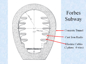
The Forbes Subway, that served these early customers, was a concrete tunnel with cast iron racks on both walls for supporting the four copper conductor, rubber insulated, lead-covered cables in each circuit [Fig 13].xv The use of low cost Niagara power enabled these companies, and other soon to follow metallurgical and chemical companies, to greatly reduce the cost of their products. Aluminum is a classic example.
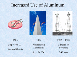
In the mid 1800’s Napoleon III had a set of aluminum forks and spoons made for his most honored guests; less important guests used gold or silver tableware.xvi In 1884 the cap for the Washington Monument was a 6¼-pound piece of aluminum, the largest made to that date in the United States. During 1905 and 1906 the Niagara, Lockport and Ontario Power Company used about 260 tons of aluminum overhead conductors to transmit Niagara power to Syracuse [Fig. 14].xvii By October 1896, when the third 5000-hp turbo-generator was placed in operation, the demand for electricity locally exceeded the capacity.xviii Arrangements were made for additional capacity.xix
References
i. Adams, Niagara Power, 2:220. “dc distribution limits,” 76. Gardner Dales, “The Story of Nikola Tesla: The War of the Currents,” Tales from Gardner Dales (Western Division Historian, Niagara Mohawk Electric Company, n.d., photocopy), 17-22.
ii. “dc distribution limits,” 76. “Engineering the Electric Century: Polyphase ac systems come of age at the Columbian Exposition and Niagara Falls,” Electrical World, July 15, 1973: 30. Adams, Niagara Power, 2:193. Lewis B. Stillwell, “The Electric Transmission of Power from Niagara Falls,” Transactions of the American Institute of Electrical Engineers, 18, (1901): 457.
iii. George D. Shepardson, Electrical Catechism: An Introductory Treatise on Electricity and its Uses, 2d. ed., (New York, NY: McGraw-Hill Book Company, 1908), 387-390. “Polyphase ac systems,” 30.
iv. Adams, Niagara Power, 2:435.
v. Ibid., 74, 182, 194, 233.
vi. Ibid., 227.
vii. Ibid., 233, 419.
viii. Ibid., 235.
ix. Ibid., 236.
x. Ibid., 411-412.
xi. Ibid., 223-246.
xii. Ibid., 417.
xiii. Ibid., 39.
xiv. Ibid., 39.
xv. Ibid., 46.
xvi. World Book Encyclopedia, 1971 ed., s.v. “aluminum.”
xvii. Author’s calculation based on Ralph D. Mershon, “The Transmission Plant of the Niagara, Lockport and Ontario Power Company,” Transactions of the American Institute of Electrical Engineers, 26, Part II, (1907): 1277. Tower Department, Transmission Towers (Pittsburgh, PA: American Bridge Company, 1925), 171.
xviii. Adams, Niagara Power, 2:39.
xix. Ibid., 247.
Niagara to Buffalo Transmission Lines
In the late 19th century about 400 steam boilers rated 33,500 hp were installed in Buffalo. With coal at about $2 per ton, the price for electric power to be competitive could be estimated.i
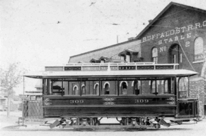
Potential customers included the street railway companies that had earlier converted from horse cars to electric trolleys like the one shown here in front of Buffalo Street Railway Company’s Stable No. 2 [Fig. 6.1]. On January 14, 1896, after much difficulty, the City of Buffalo granted an electricity distribution franchise to the Niagara Falls Power Company; municipal ownership had been rejected.
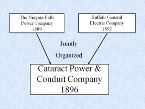
In June the franchise was assigned to the newly incorporated Cataract Power and Conduit Company, which was jointly organized by Niagara Falls Power and Buffalo General Electric for the purpose of the sale and distribution of electricity in Buffalo at wholesale [Fig. 6.2].ii Transmission franchises were secured from the various municipalities between Niagara Falls and Buffalo.iii Proposals for equipment to transmit 10,000 electrical horsepower from Niagara Falls to Buffalo were received from Westinghouse and General Electric. General Electric was awarded the contract for the design and construction of the transformer station in Niagara Falls, the transmission line to Buffalo and the transformer station in Buffalo, including the rotary converters to provide direct current for trolley service.
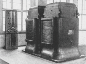
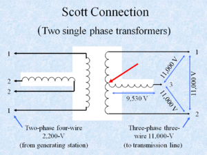
iv Two single-phase air-cooled or ‘air blast’ 930-kW transformers were installed at Niagara [Fig. 6.3}.
They were Scott connected from 2-phase 4-wire 2200-V to 3-phase 3-wire 11,000-V [Fig. 6.3].v The ‘Tee’ connection of the two high voltage windings gives three phase [Fig.
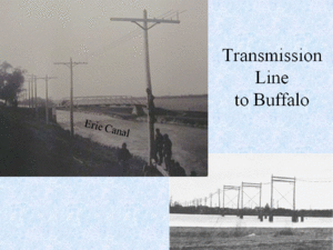
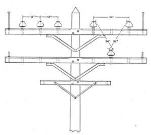
6.4]. The 22-mile transmission line consisted of cedar wood poles with 12 foot pine crossarms supporting three 350,000-cmil, 19 strand, bare copper conductors [Fig. 6.5].
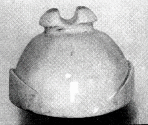
The arrangement on the crossarms was originally 18 inch horizontal spacing but was changed to 36 inch triangular spacing to deter vandals who threw short pieces of wire across two or more conductors causing short circuits [Fig. 6.6].vi Insulators proved to be a big problem. The first ones were dry process porcelain, which passed a 40,000 V dry test but were porous. About 40,000 of these insulators were rejected because they failed a 20,000 V wet test.
These were soon replaced with wet process porcelain insulators, which passed a 40,000 V wet test [Fig. 6.7].
vii
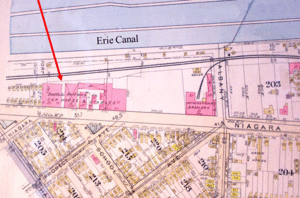
At the Buffalo end, the last 4000 feet was underground cable to the generating station of the Buffalo Railway Company on Niagara Street at Prospect Avenue [Fig. 6.8] where three 250-kW 11,000-V to 375-V transformers connected in delta supplied two rotary converters for street railway purposes. The rotary converters operated in parallel with the trolley company's steam engine driven 550-volt dc generators.viii Service was inaugurated November 15, 1896. Overall efficiency was 79.6%.ix
In 1896, protecting devices for transmission lines were conspicuous by their complete absence. The oil switch had not yet been conceived and there was no method known which could interrupt a short circuit on a line with the capacity at Niagara without shutting down the entire system.
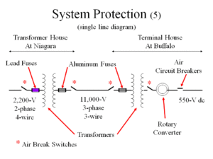
At Niagara lead fuses were used on the 2200-V side of the transformers and aluminum fuses on the 11,000-V side [Fig. 6.9]. At Buffalo 11,000-V aluminum fuses were used on the line side of the transformers and air circuit breakers on the load side of the rotary converters. The fuses proved to be totally inadequate and were removed. The only alternative was to shut down the entire system by causing the generator field circuit breakers to trip with a persistent short circuit. Air break switches were used for synchronizing and disconnecting but were useless to interrupt short circuits.x Years ago an employee related to the author how he been told that when a Niagara Falls operator opened an air break switch, another man stood by with a pail of sand to quench the arc.xi Lightning was a problem. Initially the pole line had a ground wire made of iron barbed wire above the phase conductors. After ground wire breaks caused outages, the ground wire was removed. Early lightning arresters failed to interrupt the arc.
xii
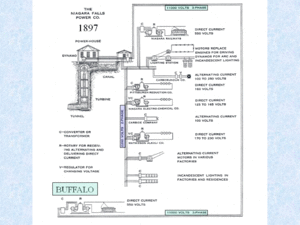
Figure 6.10 shows the Niagara Falls Power Co. distribution system in 1897. The local Niagara Falls load was supplied 2200 V by two-phase four-wire or single phase two-wire and consisted of a mixture of ac and dc applications plus motors and lighting. The Buffalo electric trolley load was less than 2,000 hp.xiii
Niagara Falls customers
objected to having their electricity interrupted for faults on the Buffalo line.xiv Continuity of service requires some means be used to disconnect defective portions of the transmission system. As the Niagara Falls load grew more units were added and it became possible to sectionalize the 2200-V bus at Niagara to supply the Buffalo load from separate generators [Fig. 6.11].xv
References
i. Adams, Niagara Power, 1:340.
ii. Ibid., 1:339-340. Niagara Mohawk Story, 79.
iii. Adams, Niagara Power, 1:337.
iv. Adams, Niagara Power, 2:248.
v. Ibid., 289. Stillwell, “Electric Transmission,” 497.
vi. Adams, Niagara Power, 2:287.
vii. Ibid., 274-275.
viii. Ibid., 275. Stillwell, “Electric Transmission,” 497.
ix. Adams, Niagara Power, 2:276.
x. Ibid., 283-285. Stillwell, “Electric Transmission,” 497.
xi. Related to the author by Alex Graham, an NMP employee, ca. 1954.
xii. Adams, Niagara Power, 2:278.
xiii. Ibid., 251. Stillwell, “Electric Transmission,” 497.
xiv. Adams, Niagara Power, 2:284.
xv. Ibid., 284.
