Archives:Transformers at Pittsfield, part 3: Difference between revisions
No edit summary |
No edit summary |
||
| Line 321: | Line 321: | ||
F.F. Brand was born in 1884 in Sussex, England. In 1902, he received degrees in Electrical Engineering from both Finsbury Technical College and the City Guilds of London Engineering College. He went to work for the British Thomson-Houston Company in Rugby, England in their meter testing department. Later, he was put in charge of the experimental instrument laboratory there. | F.F. Brand was born in 1884 in Sussex, England. In 1902, he received degrees in Electrical Engineering from both Finsbury Technical College and the City Guilds of London Engineering College. He went to work for the British Thomson-Houston Company in Rugby, England in their meter testing department. Later, he was put in charge of the experimental instrument laboratory there. | ||
In 1906, he chanced to meet [[Cummings C. Chesney]] and, through him, came to the United States to join the Stanley Company in Pittsfield. As an apprentice, he was engaged in such tasks as washing marble switchboard slabs and carrying copper bars around the shop. | In 1906, he chanced to meet [[Cummings C. Chesney|Cummings C. Chesney]] and, through him, came to the United States to join the Stanley Company in Pittsfield. As an apprentice, he was engaged in such tasks as washing marble switchboard slabs and carrying copper bars around the shop. | ||
In the early 1920's, Mr. Brand, along with Mr. J.J. Frank, was largely responsible for the design of the first 220-kv transformers ever built. These were used by the Big Creek Power Company in southern California. | In the early 1920's, Mr. Brand, along with Mr. J.J. Frank, was largely responsible for the design of the first 220-kv transformers ever built. These were used by the Big Creek Power Company in southern California. | ||
| Line 1,078: | Line 1,078: | ||
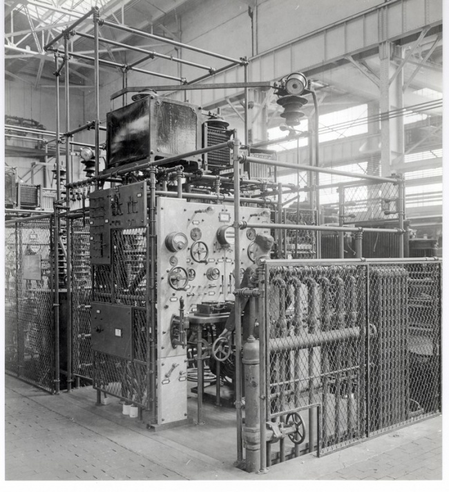
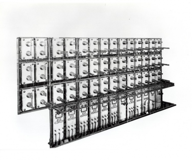
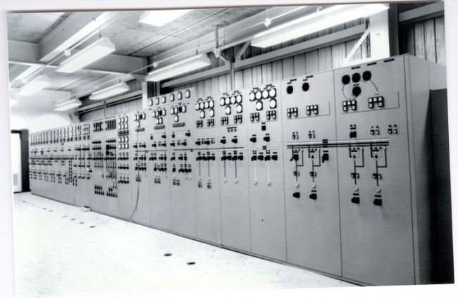
In addition, it controlled the routing of all generators, as well as ten capacitor banks ("A" through "J"), to the Building 100 test berths. | In addition, it controlled the routing of all generators, as well as ten capacitor banks ("A" through "J"), to the Building 100 test berths. | ||
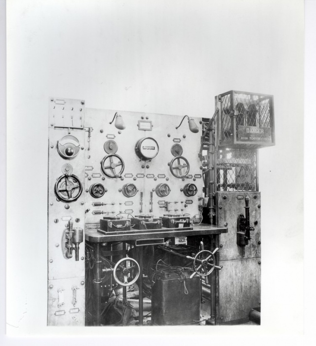
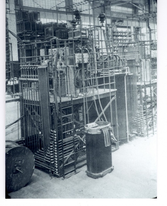
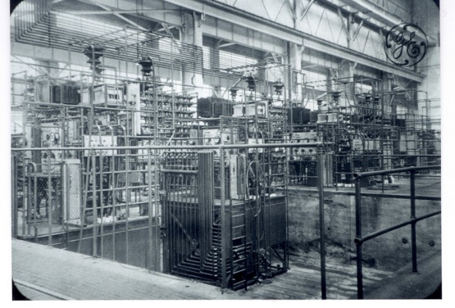
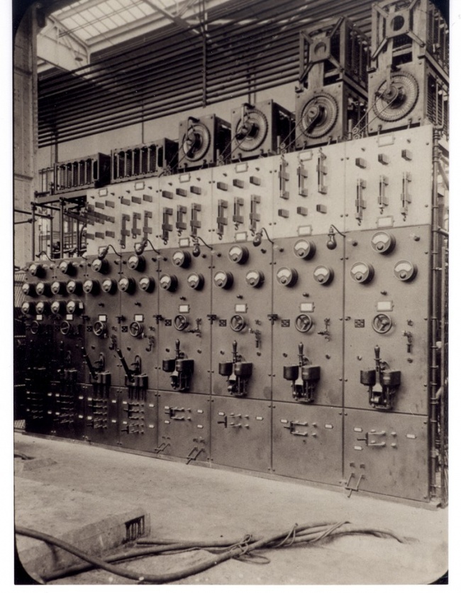
[[Image:Blalock - page 304.jpg|thumb|center|Chamblee Panel in Building 100A courtesy of General Electric Company]] | [[Image:Blalock - page 304.jpg|thumb|center|650px|Chamblee Panel in Building 100A courtesy of General Electric Company]] | ||
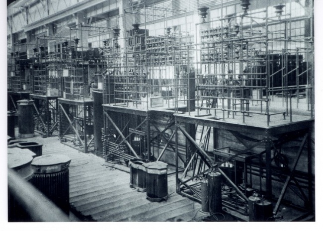
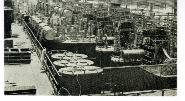
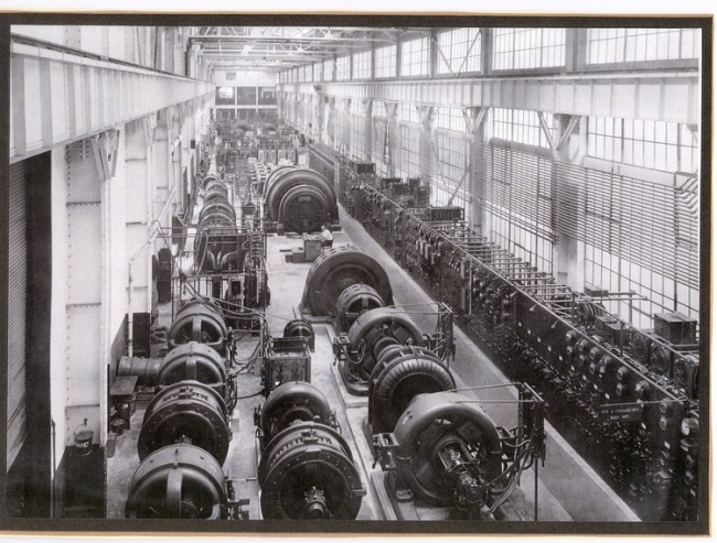
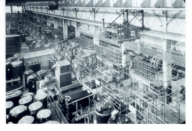
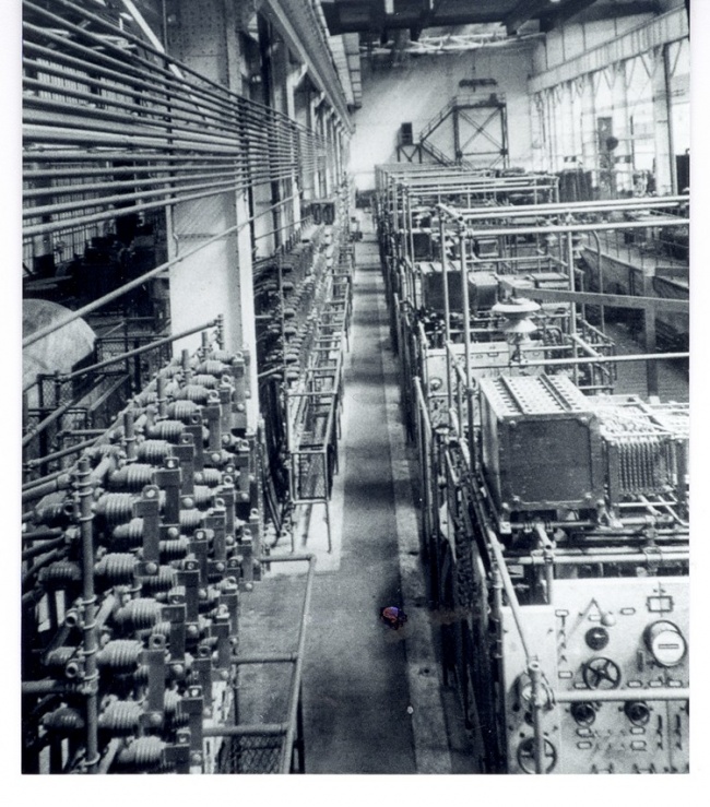
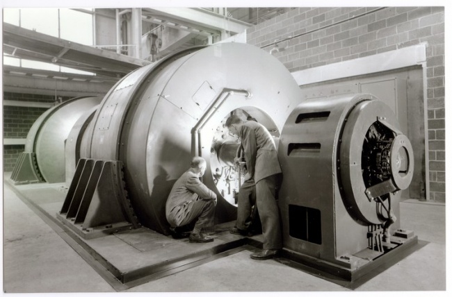
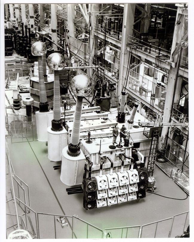
[[Image:Blalock - page 304 (bot).jpg|thumb|center|650px|Generators 172 (foreground) and 174 in Building 100A courtesy of General Electric Company]] | [[Image:Blalock - page 304 (bot).jpg|thumb|center|650px|Generators 172 (foreground) and 174 in Building 100A courtesy of General Electric Company]] | ||
| Line 1,107: | Line 1,107: | ||
#20 - starting of drive motor for Gens. 116, 120, & 150 | #20 - starting of drive motor for Gens. 116, 120, & 150 | ||
Note: "12Y" refers to test berths still in use in Building 12Y. | |||
The starting of most of the motor-generator sets was straightforward; the exceptions were the 12-Mva sets (172/174, 176/178, and 400/402). These sets were equipped with 5000-horsepower synchronous drive motors which were not arranged to be self-starting. Instead, these sets were equipped with 1000-horsepower wound-rotor induction motors which acted as start motors to bring the sets up to speed. This took anywhere from about three minutes to almost ten minutes, depending on the time of year (that is, how cold the oil was in the bearings of the machines!). | The starting of most of the motor-generator sets was straightforward; the exceptions were the 12-Mva sets (172/174, 176/178, and 400/402). These sets were equipped with 5000-horsepower synchronous drive motors which were not arranged to be self-starting. Instead, these sets were equipped with 1000-horsepower wound-rotor induction motors which acted as start motors to bring the sets up to speed. This took anywhere from about three minutes to almost ten minutes, depending on the time of year (that is, how cold the oil was in the bearings of the machines!). | ||
| Line 1,121: | Line 1,121: | ||
== Epilogue == | == Epilogue == | ||
"I have a very personal affection for a transformer. It is such a complete and simple solution for a difficult problem. It so puts to shame all mechanical attempts at regulation. It handles with such ease, certainty, and economy vast loads of energy that are instantly given to or taken from it. It is so reliable, strong, and certain. In this mingled steel and copper, extraordinary forces are so nicely balanced as to be almost unsuspected. This equilibrium is remarkable. It is like putting on the pans of a delicate chemist's balance ten-pound weights so exactly timed in their application that never a tremor stirs the needle from its mark." - [[William Stanley]] | "I have a very personal affection for a transformer. It is such a complete and simple solution for a difficult problem. It so puts to shame all mechanical attempts at regulation. It handles with such ease, certainty, and economy vast loads of energy that are instantly given to or taken from it. It is so reliable, strong, and certain. In this mingled steel and copper, extraordinary forces are so nicely balanced as to be almost unsuspected. This equilibrium is remarkable. It is like putting on the pans of a delicate chemist's balance ten-pound weights so exactly timed in their application that never a tremor stirs the needle from its mark." - [[William Stanley|William Stanley]] | ||
Stanley was actually in the employ of [[George Westinghouse|George Westinghouse]] when he first demonstrated the use of the transformer in lighting Great Barrington, Massachusetts in 1886. Following this highly successful demonstration, the "Westinghouse Alternating Current System" was put on the market and Stanley began to be treated very shabbily by George Westinghouse. For this reason, as well as for reasons of health (Stanley suffered from asthma-like symptoms and the soot-laden air of Pittsburgh, which was the home of the Westinghouse Company, did nothing for his physical well-being), Stanley began his own company in Pittsfield. | Stanley was actually in the employ of [[George Westinghouse|George Westinghouse]] when he first demonstrated the use of the transformer in lighting Great Barrington, Massachusetts in 1886. Following this highly successful demonstration, the "Westinghouse Alternating Current System" was put on the market and Stanley began to be treated very shabbily by George Westinghouse. For this reason, as well as for reasons of health (Stanley suffered from asthma-like symptoms and the soot-laden air of Pittsburgh, which was the home of the Westinghouse Company, did nothing for his physical well-being), Stanley began his own company in Pittsfield. | ||
Revision as of 17:02, 25 April 2011
Continued from Transformers at Pittsfield, part 2
Chapter 15: Early Test Power System
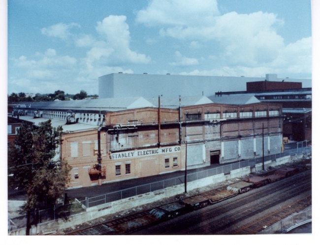
The testing of transformers built at the Morning-side plant of the Stanley Electric Manufacturing Company took place in Building 1, the main transformer assembly building, which was built in 1901. In 1907, when the plant became the Pittsfield Works of the General Electric Company, adjoining Building 2 was completed and the testing operation expanded into this new area. Similarly, two years later, Building 3 was added and the testing operation expanded again.
In 1914, the Building 12 complex was begun and transformer testing commenced in. the east and west bays of that building in 1917. In 1924, additional test berths were added in new Building 12X, which adjoined Building 12 on the east. Then, in 1950, Building 12Y was added to the east side of Building 12X, and more test berths were included at the north end of that new building.
Finally, in 1966, construction was begun on the new Building 100 and, by 1968, the assembly and testing of the largest transformers were being handled in that facility. This remained the case until the closing of the transformer operation in 1987.
All of these expansions of the testing facilities involved the construction of larger and larger test berths to handle the increasing sizes of transformers which were being built. However, a major portion of the planning involved in these expansions was in regard to the necessary additions to the power system which supplied these new berths with all of the various types of electric power required to conduct the tests.
Transformer testing requires that power having a wide range of voltage and current levels be available. Furthermore, during the early decades of transformer testing, this power had to be available over a range of frequencies as well since 60-Hertz had not yet been established as the absolute standard frequency in this country.
Early on, it was recognized that the best way to supply power with this degree of flexibility was to use motor-generator sets. The generators were driven by electric motors which obtained their power from the plant power house and, eventually, from the local electric utility. The use of motor-generator sets allowed the 60-Hertz power available in the plant to be converted to the particular type of power needed for each testing situation.
The test power system was a very important aspect of the testing facilities in the Pittsfield transformer operation. The somewhat detailed description of this system which follows serves to convey a better understanding of the transformer testing process, a very important part of the transformer manufacturing cycle.
As mentioned, in the early years of transformer testing, various frequencies had to be dealt with. At this point, due to the historical nature of the discussion which follows, I choose to revert to the now archaic term "cycles" (short for cycles per second) to designate frequency rather than the present "Hertz".
As described in Chapter 2, the Pittsfield plant's power system was, in the early years, a two-phase, 60-cycle, 2300-volt system. Three-phase power, as well as other voltages, could be obtained from this system by the use of appropriate transformers. However, if frequencies other than 60-cycles were needed, the use of motor-generators was required.
Since other frequencies were in use in this country during the early decades of this century, transformers designed and built for use on those frequencies had to be tested at those frequencies. The major frequencies in use were:
25-cycles originated with the first hydroelectric installation at Niagara Falls, New York; persisted in use in western New York State and in Canada for many years (and, to some extent, still does!).
30-cycles - introduced by the Westinghouse company for use with large, slow-speed motors; now long obsolete.
40-cycles - introduced by General Electric in the 1890's to replace 25-cycles and 60-cycles; now obsolete.
50-cycles - originally used in southern California, for somewhat obscure reasons; now obsolete in this country, but still a standard in several European countries.
60-cycles introduced by Westinghouse as a standard frequency for general lighting purposes, around 1890; now the standard frequency in this country as well as in much of the rest of the world.
Since the frequency produced by an alternating current generator is a function of the speed at which it is driven, the method used in the Pittsfield plant to produce the above frequencies (including 60-cycles) was the use of D.C. motors to drive the test generators. The speed of operation of a D.C. motor is, simply, a function of the voltage supplied to it.
Motor-generator sets known as "prime movers" were used to provide the D.C. voltage (the term referring to their function as a basic source of motive power). The motors for these sets operated from the two-phase, 60-cycle plant power system.
One of the common test generator ("T.G.") speeds used to produce 60-cycle power for the test berths was 720-rpm. Thus, since the speed of the D.C. "drive motors" for the various test generators was directly proportional to the D.C. voltage, the prime movers were designed to provide the following voltages:
| D.C. voltage | Speed, rpm | T.G. cycles |
| 550 | 720 | 60 |
| 440 | 600 | 50 |
| 330 | 480 | 40 |
| 275 | 360 | 30 |
| 220 | 300 | 25 |
Two sets of three-wire (dual voltage) D.C. generators were used as prime movers. One set of generators produced 550/275 volts, while the other set produced 440/330/220 volts. 330 volts was obtained by using one 220/110 volt generator in series with one-half of a second 220/110 volt generator. Thus, the "one-line" schematic of this system would appear as follows:
As explained in Chapter 14, it was imperative that the correct frequency be used for core loss tests in order to obtain an accurate measurement of that loss. Since the function of the test generator in this case is to magnetize the transformer core, the test generators used for this purpose were sometimes referred to as "magnetizers". It was common practice to use the correct frequency for load loss tests as well. However, the need for absolutely correct frequency when conducting these tests is not quite so acute. This is because a large percentage of the total load loss is composed of resistance loss in the copper conductors; this loss is not a function of frequency (ignoring any minor errors which might be due to "skin effect").
While the majority of test generators functioned as "magnetizers", providing power of correct frequency and voltage to excite the cores of transformers being tested, some generators were used as "loaders". This function had to do with providing current to load the windings of transformers during heat runs (more about this later). In addition, some generators were parts of frequency-changer sets which provided frequencies higher than 60-cycles for induced-voltage tests.
In order to keep track of all of these various machines (both motors and generators), a numbering system was devised early in this century in the plant which assigned an even number to any A.C. machine and an odd number to any D.C. machine; this was regardless of whether the machine functioned as a motor or as a generator. In later years, however, the need for D.C. drive diminished because very nearly all transformers built were designed for 60-cycles; the other earlier frequencies had fallen out of use, or nearly so. Thus, the test generators could be driven by "synchronous" A.C. motors operating directly from the 60-cycle power' system in the plant. As this became the case, the numbering system gradually changed so that A.C. generators were given even numbers and A.C. motors were given odd numbers.
Building 1 of the Pittsfield plant was constructed in 1901, and adjoining Building 2 was added in1907. Originally, both the test "power plant" and. the test berths themselves were located in Building 1. However, after 1907, the berths were moved to Building 2. When adjoining Building 3 was completed in 1909, some of the motor-generator sets were moved there. Apparently, the prime mover motor-generator sets remained in the test power plant in Building 1. By 1913, new test generator sets were being added in Building 3.
In Building 1, the original 550/275 volt D.C. prime mover set consisted of Generator No. I driven by two-phase Motor No. 2; the 440/330/220 volt D.C. set consisted of Generator Nos. 3 and 5 driven by Motor No. 6.
Following is a tabulation of known generators used in the Building 1-2-3 test operation, circa 1913. The term "sine wave" means that these generators had very pure sine wave outputs; these were used for hi-pot test power as well as any other applications requiring nondistorted A.C. waveforms.
The two Thomson-Houston generators produced a frequency of 125-cycles. This was a standard frequency of the Thomson-Houston Company of Lynn, Massachusetts. Thomson-Houston was merged with the Edison General Electric Company in 1892 to form the present General Electric Company. The Lynn plant became the Lynn Works of General Electric. It is possible that 125-cycle transformers were built in Pittsfield.
Most of the magnetizer generators produced frequencies of 25 through 60 cycles, as described above. Three of these, however, had basic frequency ratings which were 25-cycles (a great many 25-cycle transformers were built during this era). Two generators were capable of producing frequencies as low as 15-cycles, should that ever have been needed.
The 24-cycle "loader" frequency will be explained.
Building 1-2-3 Test Generators
| Generator | Frequency | Drive | Notes |
| 22,24,30, 32,34 | 25-60 | DC | |
| 36 | 25 | DC | |
| 38,40,42 | 25-60 | DC | |
| 46/48 | 200 | Sync. | Induce Tests |
| 50/56 | 15-25 | DC | |
| 52/54 | 25-60 | DC | |
| 58 | 25-60 | DC | |
| 60/62 | 24 | Sync. | Loaders |
| 64,66,68, 70,72 | 25-60 | DC | |
| 74 | 60 | Induction | Hi-pot Tests |
| 76/78 | 200 | DC | Induce Tests |
| 80 | 25-60 | DC | (sine wave) |
| 82,86 | 125 | DC | Thomson-Houston |
| 84 | DC | DC | Resistance Test |
| 88 | 24 | Sync. | Loader |
| 90 | 60 | Induction | Ratio test |
| 94/96 | 25-60 | DC | |
| 98 | 420 | Sync. | Induce Tests |
| 102 | 24 | Sync. | Loader |
| 104 | 60 | DC | Loader |
| 106, 108, 110, 112, 114, 116, 118 | 25-60 | DC | |
| 120 | 25-60 | DC | (sine wave) |
The complexity of this system is obvious! Machine numbers not included in the above table were DC drive motors, synchronous motors, and DC exciters providing field current for the test generators.
Generator 120 was the latest addition. It was primarily used for hi-pot tests and continued in use until the plant closing in 1987! It was moved twice, first to Building 12 and then to Building 100A.
The capacities of the magnetizer test generators ranged from 25-Kva to 500-Kva. The largest capacity generators were the loaders (3000 to 4000 Kva). The generators in pairs with a slash ("/") were driven by a common motor, and were referred to as "double-ended" sets.
Even though Generator 84 (used to measure winding resistances) was DC, it was given an even number; this was probably done simply because it was a generator, and all other generators had even numbers'.
As might be expected, the operation of such a complex system as this produced some interesting events. For example, when Generator 98 (for induce tests) was installed in 1913, considerable problems were encountered in trying to start the set and bring it up to speed. The set had a "direct-connected" exciter which was supposed to function as a start motor for this purpose. However, according to Test Record sheets for this effort when first attempted:
"The (exciter) armature insulation has been heated very excessively during starting tests, causing the insulation to melt."
"After failing to start the set from the exciter alone, running the DC current up to 600 amps, holding 500 amps on exciter it could be started with a bar (all one man could do) and would be brought up to speed on the exciter, but it was very slow (over fifteen minutes) and caused the exciter to heat excessively."
"The machines were started from both the AC and DC .ends at same time - 300 amps on DC end."
The last comment indicates that the set was started by using both the exciter and the main (two-phase synchronous) drive motor together as start motors. The reference to the use of a "bar" means that a test man inserted an iron bar into the rotor of the machine and leaned on it so as to break the machine's standing friction; then, as the machine began to move, he pulled the bar out as fast as he could!
This motor-generator set was designed and built by General Electric (in Schenectady, New York); it is not known whether Pittsfield filed any formal complaints about the difficulty with starting the set.
Another interesting incident (in 1915) involved the improper use of 500-volt rated fuses in 2300-volt power circuits. From a memo:
"Yesterday we had an occasion to note the action of these fuses in blowing! The arc from the top of the cut-out swept to the iron work, and short-circuited the motor, opening up all the switches in the Power Station."
Power for Heat Runs
Heat Runs were extended time tests designed to determine how hot a transformer would get when fully loaded, in service. A transformer could be energized at rated voltage on one winding, with the other winding fed into some sort of loading device. This was actually done in some cases, with the loading device taking the form of a large "water rheostat". The load on the transformer was manifested by the heating of the water.
With larger transformers, however, this procedure was very energy wasteful. Therefore, "tricky" methods were devised to cause rated current to flow in the transformer windings, with full voltage excitation, without actually consuming large amounts of electrical power. Such methods involved the use of two different test generators simultaneously.
Sometimes, a single transformer could be given a heat run simply by connecting a suitable generator to each of its two windings. Since both generators were driven by motors operating from the same power system, suitable adjustment of the fields of the two machines would cause full load current to flow in the windings of the transformer under test. This was referred to as a “loading-back” test. The power involved flowed from one generator, through the transformer, and back to the power system through the second generator.
The loading-back technique was more often used in the testing of large motors and generators, where it was often referred to as a "pump-back" test.
More commonly, however, if two identical single-phase transformers were available, a type of test known as a "bucking" heat run was conducted. This technique allowed for better control of the voltages and currents involved. Early in this century, it was actually quite common to have more than one transformer of a given type. This had to do with the fact that three-phase transformers were not yet in common use; three single-phase transformers were used to make up a three-phase bank. Thus, a customer would order three transformers of identical rating (and, sometimes, four if a spare was desired).
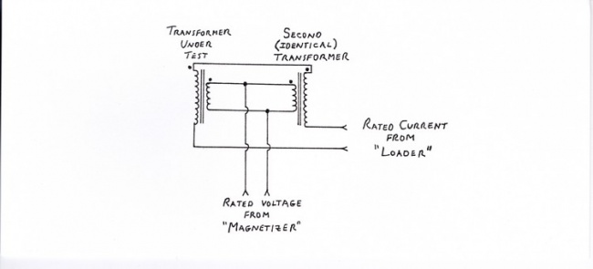
The connections for a bucking heat run on a single-phase transformer were as shown below (only one of the pair of transformers was actually under test):
The dots at the tops of the transformer windings are polarity indicators. They show that the loading current was made to flow in opposite directions in the two windings. With the other two windings connected in parallel, as shown, load current would flow in the loop formed by those two windings as well. Thus, the magnetizer test generator could simply supply rated voltage at the terminals of those windings. Only the very small amount of transformer exciting current would be required from this generator.
This magnetizing voltage excited the core loss portion of the transformer's total loss, and had to be at exactly the rated frequency of the transformer. It was less important that the loading current supplied by the loader generator be at exactly this frequency. This was because a large portion of the load loss is composed of winding resistance loss which is not dependent on frequency. The remainder of the load loss, the magnetic stray and eddy loss, is; thus, the loading frequency had to be at least close to the rated transformer frequency.
Advantage was taken of this fact; that is, the frequency of the loading current was intentionally offset slightly from the rated frequency of the transformer. The magnetizing test generators had DC drive motors and were not "synchronous" with the plant power system. It had been learned that attempts to use two such machines adjusted as close as possible to the same frequency for bucking heat run tests led to "hunting" problems due to the interaction between the two generator currents.
A great many transformers built during the early part of this century were designed for operation on 25-cycle power systems. Thus, special loader generators were installed which produced a frequency equal to 24-cycles. (see table above). The use of 24-cycles for the loading current during bucking heat runs satisfied the requirement to offset this frequency slightly from the rated frequency for 25-cycle transformers. The standard operating procedures of the day required that the loading current frequency be within five per cent of the rated frequency of the transformer. This was satisfied by using a current of 24-cycles.
One of the loaders (Generator 104) was designed to produce frequencies as high as 60-cycles, and had a DC drive motor. Thus, its actual output frequency was capable of adjustment to any value by adjusting the speed of the drive motor. This machine was used to provide loading current for bucking heat runs on transformers rated for frequencies other than 25-cycles.
The Building 1 Test Power Plant
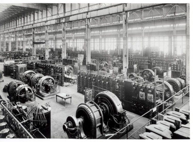
Chapter 16: The Building 12 Complex
Building 12, a new transformer assembly and testing building, was begun in 1914; the first transformer was tested there in 1917. The building still stands to the east of the Building 1-2-3 complex, separated from the latter by an open yard area. This area was known as "3C Yard" because it contained a small building which bore that designation. That building was partially sunken and contained pumps and filters for use with the extensive mineral oil system needed to fill transformers for the purpose of testing.
Building 12 consists of three side-by-side sections, just as Buildings 1-2-3. The main Building 12 sections are known as the "East Bay" and the "West Bay". To the west of the latter is a section known as the "lean-to" because of the nature of its roof structure. This section came to be known as the "Power Bay" because it contained all of the motor-generator sets needed to supply power to the new testing operation in Building 12. The Power Bay will be described in detail in Chapter 17.
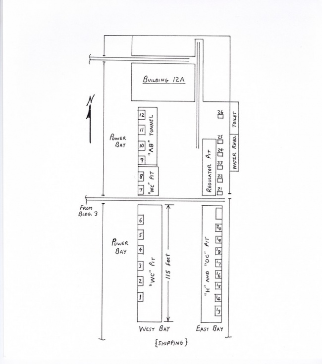
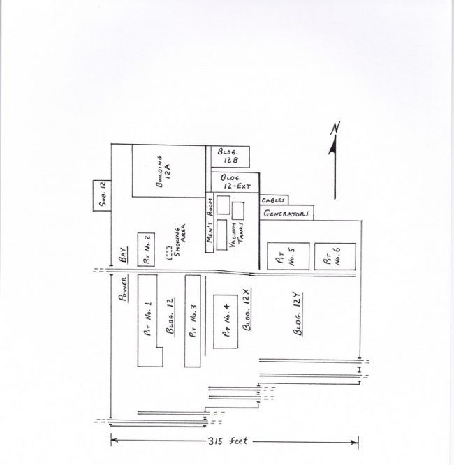
Transformer testing was carried out in both of the main bays of Building 12 (East and West). Following is a drawing of the test berth layout in the building.
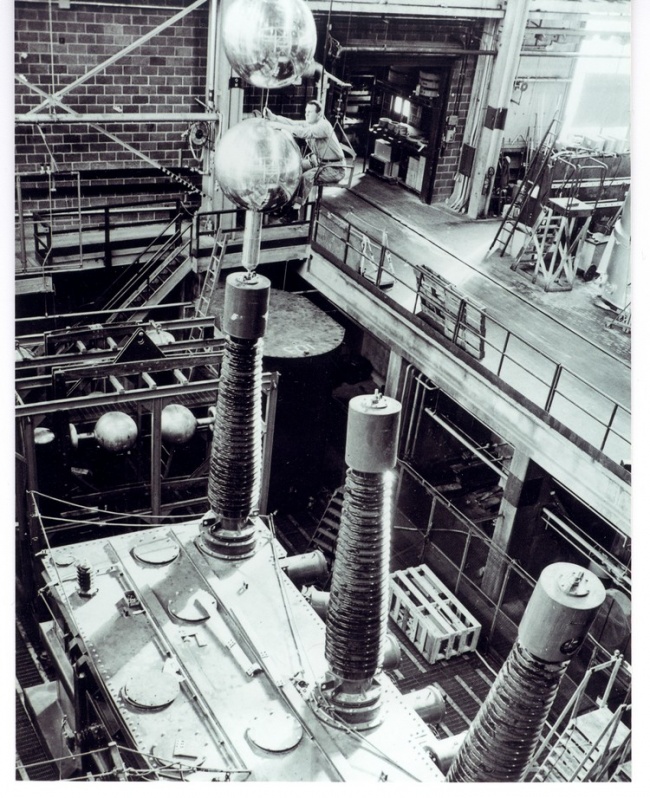
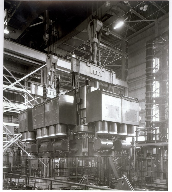
For the most part, the berths consisted of pits into which the transformers were lowered, by overhead crane; the control panels were installed alongside at the main floor level. This arrangement made it easier for the test berth operators to reach the terminals on the tops of larger transformers.
Test berths 1 through 8 were used for the testing of water-cooled transformers. These transformers were equipped with internal pipe coils through which water was circulated to cool the transformer oil. Thus, these berths were equipped with city water connections for this purpose during testing.
Berths 9 through 12 were designed for the testing of "air-blast" transformers. These units were cooled by means of an external blower arrangement which forced air up through the body of the transformer to cool the windings. These berths were located over a tunnel fed with air from a permanent blower arrangement, so as to provide this cooling function during testing.
Berths 13 through 20 were used for the testing of oil-cooled transformers; that is, transformers which were cooled by the circulation of the oil contained in their tanks. Sometimes, this was by natural convection ("self-cooled"). The oil circulated on its own through a system of vertical pipes welded to the outside of the tank and was cooled. In later years, however, as the transformers became larger, pumps were used to force the oil through external radiator arrangements so as to provide more efficient cooling.
The early transformer type designations were as follows:
| Description | Single-phase | Three-phase |
| Air-blast | "AB" | "ABT" |
| Water-cooled | "WC" | "WCT" |
| Self-cooled (core form) | "H" | "HT" |
| Self-cooled (shell form) | "OC" | "OCT" |
The terms "core form" and "shell form" refer to the style of the iron transformer core. In the shell form type, the core more nearly surrounds the windings than in the core form type. Eventually, core form transformers became the type favored by General Electric, while shell form was favored by the Westinghouse Corporation (G.E.'s major competitor in transformers).
Berths 21 through 26 were used for the testing of regulators. These are specialized transformer-like devices whose function is the regulation of voltage on electric power distribution lines. Today, this regulating function is always done automatically by means of control devices built into the regulators. Regulators were (and still are) relatively small as compared to large power transformers. For load loss testing and heat runs, they could be loaded by means of water rheostats (instead of resorting to bucking heat runs); such rheostats were installed in an area next to these berths.
The railroad tracks shown running through the center of Building 12 ("from Bldg. 3") were used for a battery-operated "transfer car" which moved heavy transformers from one bay to another. Each of the three bays was equipped with overhead cranes to lift these units anywhere within that bay.
Frederick F. Brand
F.F. Brand was born in 1884 in Sussex, England. In 1902, he received degrees in Electrical Engineering from both Finsbury Technical College and the City Guilds of London Engineering College. He went to work for the British Thomson-Houston Company in Rugby, England in their meter testing department. Later, he was put in charge of the experimental instrument laboratory there.
In 1906, he chanced to meet Cummings C. Chesney and, through him, came to the United States to join the Stanley Company in Pittsfield. As an apprentice, he was engaged in such tasks as washing marble switchboard slabs and carrying copper bars around the shop.
In the early 1920's, Mr. Brand, along with Mr. J.J. Frank, was largely responsible for the design of the first 220-kv transformers ever built. These were used by the Big Creek Power Company in southern California.
In 1933, he was appointed Manager of Engineering in the Pittsfield plant, reporting directly to Works Manager, L.E. Underwood. He retired in 1949, after forty-three years of service to the General Electric Company, and was succeeded by Dr. Karl B. McEachron. Mr. Brand died in 1950.
Mr. Brand was very instrumental in the design and implementation of the Building 12 transformer testing facilities, particularly the test power system.
In 1924, the construction of Building 12X was soon to begin. This building was attached to the east side of Building 12, and was referred to as the "Super Transformer Building" at the time because of its ability to handle much larger transformers. Building 12X included new Test Berths 26, 27, and 28 ("26" replacing a former berth with that number in Building 12).
By 1945, in Building 12, a Test Berth "lA" had been added to the south of Berth 1 for the testing of high voltage porcelain bushings. Berths 1 through 8 were still in use for the testing of transformers. Air blast Berths 9 through 12 were being used for the testing of forced-air cooled railway locomotive transformers.
The sunken pits for Berths 13 and 14 had been closed and these berths were being used for the testing of high voltage specialty products such as rectifiers, hi-pot testing sets, and impulse generators.
Berths 15 through 17 were in use for the testing of step-type voltage regulators; that is, regulators in which the voltage control is accomplished by the use of a switching mechanism. Berths 19 through 25 were used for testing induction regulators, in which the voltage control occurs by physically rotating one winding with respect to the other. This changes the magnetic coupling between the windings.
Berth 18 was used for testing "LRC" (load ratio control) reactors. These were components in the load tap-changing mechanisms of large transformers which allowed for the changing of taps under load.
It is interesting that so many of the Building 12 test berths were still in use because, when Building 12 was built thirty years earlier, fifteen of these berths were old ones which had been moved from Building 2!
In 1949, construction began on Building 12Y which was attached to the east side of Building 12X. This new building doubled the plant's capacity for manufacturing transformers. Just as in Building 12, it is composed of two bays (East and West), each bay having its own set of overhead cranes. The transfer car track was continued from Building 12X through both new bays.
More new test berths were included in Building 12Y, at the north end. These were large berths and were designated as Berth 30 (West Bay) and Berth 32 (East Bay). In later years, these were broken up into four berths (30 through 33).
The plan on the previous page shows, in detail, the layout of Buildings 12, 12X, and 12Y around 1950.
In Building 12, Pits 1, 2, and 3 housed most of the original test berths. However, the regulator berths in the northeast corner (Berths 21 through 26) had been replaced by an assembly area for transformer Load Ratio Control equipment. Note that, in 1950, there was a designated smoking area in Building 12!
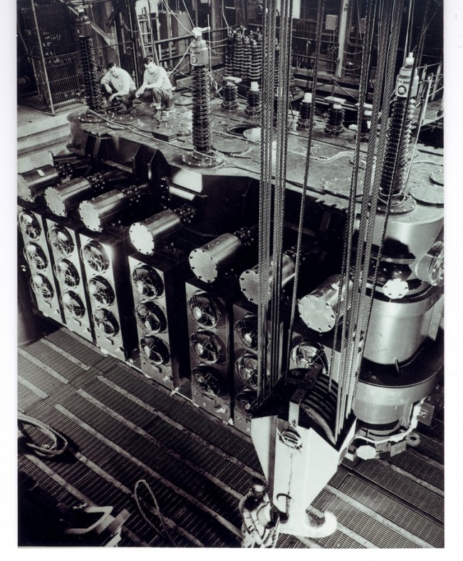
In Building 12X, Pit 4 contained Test Berths 26, 27, and 28. Berth 26 was devoted to impulse testing. The power for Berths 27 and 28 was via two sets of shared three-phase transformers. One set, referred to as the "step-ups", was rated at 6000-Kva and was used to supply magnetizing current for core loss tests and heat runs, as well as current for load loss tests. The other set of transformers (the "loaders") supplied loading current for bucking heat runs. The rating of this latter set was 24,000-Kva.
For some reason, there never was a berth designated as Berth 29. It became a common joke to refer to the Men's Room at the north end of Building 12X as Berth 29, both because of its physical location and because some of the test men seemed to spend a lot of time there!
Building 12A, at the north end of Building 12, came to be the testing area for voltage regulators; in the past, it had been the High Voltage Laboratory (before the construction of Building 9 in 1949). Building 12B, at the north end of Building 12X, was known as the "short circuit lab". Testing was done there to determine the short circuit strength of transformer windings as well as the short circuit behavior of such devices as lightning arresters and fused cut-outs.
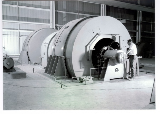
Building 12-Ext, also located at the north end of Building 12X, housed a very interesting test generator set used to supply power to the test berths in Buildings 12X and 12Y. This set was installed in 1925 and it included two 12,000-Kva generators. Since, prior to the installation of this set, the largest generators in use were rated at 3000-Kva, this came to be referred to as the "Big Set". The Big Set was unique in that it had two drive motors as well as two generators, all on the same shaft. In addition, there was a start motor on the same shaft used to bring the set up to speed.
Using the convention of numbering A.C. machines as even, these two generators were "172" and "174". The drive motors for the set were two-phase synchronous motors. This reflected the shift from D.C. drive for test generators because of the diminished need for the odder test frequencies (i.e., 30-cycles and 40-cycles). However, there was still occasional need for two frequencies other than 60-cycles. These were 25-cycles and 50-cycles. This was the reason for the two drive motors on the Big Set.
Only one drive motor was in use at a time. One of the motors was a 5000-horsepower, 720-rpm motor which drove the set when 60-cycle power was required in the test berths. The other motor was a dual-rated machine of 4400/2200-horsepower which could be operated at two speeds; namely, 600-rpm and 300-rpm (horsepower is a function of speed). This motor drove the set when the test berths required either 50-cycle or 25-cycle power.
The dual-speed drive motor was of a type known as a "consequent-pole" motor. This means that both the stator and rotor (field) windings could be connected so as to obtain the two different speeds. The speeds are related by a two-to-one ratio because the method of connection for the lower speed was such that the number of magnetic poles in the windings was effectively doubled; this halved the speed of rotation. The term "consequent-pole" means that poles of opposite polarity to those in the windings were induced in the iron core structure of the machine. Thus, the number of poles was doubled.
The start motor was a 1000-horsepower, two-phase wound-rotor induction motor. External resistance in the rotor circuit was gradually cut out so as to bring the set up to running speed. At that point, one of the drive motors would be "synchronized" to the power system and thrown on line.
An auxiliary motor-generator set consisted of a 300-horsepower two-phase induction motor driving two 125-volt D.C. exciters, one for each of the two test generators.
Thus, this rather impressive installation consisted of a total of eight rotating machines, all located in Building 12-Ext. By 1968, when Building 100 was built, Generators 172/174 (as they were known collectively) had suffered some damage from having been used as a source of power for short-circuit testing in adjacent Building 12B. Since Building 12-Ext was in the way of Building 100, the Big Set would have had to be moved if it was to continue to be used. Because of its age and condition, however, it was reluctantly agreed that it should be scrapped instead.
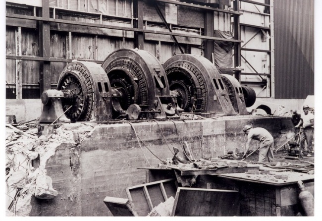
On the Building 12 Complex plan, there is an area at the north end of Building 12Y labeled "Generators". This was the location of a second motor-generator set which was installed when Building 12Y was built (1950). This set also included two 12,000-Kva generators, but had only one drive motor. It was designed to provide only 60-cycle power to the test berths. By this time, the use of 25-cycle and 50-cycle power had diminished; furthermore, the Big Set was still in use to provide these frequencies if needed. This newer generator set was known as "Generators 176/178".
It may seem odd that a motor-generator set such as "176/178" would be installed to provide only 60-cycle power, since the plant power system itself operated at 60-cycles. However, by this time, it had become standard operating procedure to use M-G sets to provide test berth power since this was a means of allowing for absolute control over voltage and current (by the controlling of the generator field). It also provided complete electrical isolation, between the test power system and the plant power system since the only flow of power from the latter to the former was in the form of mechanical power in the shaft connecting the drive motor to the test generator. This was an advantage in the event of electrical disturbances on either system.
As time went on, the need for ever greater amounts of power for testing occurred because of the increasing size of transformers being built. In 1952, a third set of two 12,000-Kva generators was installed in a small building (built for this purpose) known as Building 7J, to the north of Building 12Y. For reasons unknown, a large jump occurred in the generator numbering scheme, and these machines were known as "Generators 400/402"!
The testing of one large transformer, however, required the use of a large amount of power in a single test berth. The first attempt at a solution to this problem was the paralleling of Berths 30, 31, and 32 in Building 12Y. This allowed the outputs of all six 12,000-Kva generators (172/174, 176/178, and 400/402) to be paralleled for a total of 72,000-Kva, or 72-Mva. This, however, meant that only one transformer could be tested while all three berths were in use. This was a severe problem, production-wise.
Accordingly, a project was begun to increase both the kilovolt and the Mva capacity of Berth 32, in the East Bay of Building 12Y, so as to eliminate the need for paralleling, it with the other berths. New step-up transformers for this berth were installed outside, just to the east of Building 12Y. This bank of transformers increased the voltage capability of Berth 32 from 48-kv to 69-kv. The bank was rated at 100-Mva, and two 27-Mva capacitor banks were installed alongside of Building 7J to provide reactive Mva for load loss tests and heat runs (see Chapter 14).
This was actually the second installation of capacitor banks to supply reactive Mva for testing. At some time prior to this, Berths 30 and 31 (in the West Bay of Building 12Y) had been equipped with two 4.5- Mva capacitor banks for this same purpose.
The Berth 32 uprating project was implemented by a team composed of Walter Galusha, G.G. ("Pete") Kemp, and T.O. ("Tom") Stanfield. Also, an instrumentation design group, associated with the High Voltage Laboratory operation, provided advanced test berth instrumentation as a part of this project. This group was headed by Steve Leonard, and a key contributor to the Berth 32 project was Bert Foley. An additional appropriation of fifty thousand dollars covered this latter effort.
This new instrumentation included the use of gas-insulated coupling capacitor units to measure the three phase-to-ground voltages; prior to this, standard procedure for the measurement of voltage in test berths. had been the use of conventional potential transformers, or "P.T.'s", as are used on commercial power systems for the same purpose. Operational amplifier circuitry used in conjunction with the coupling capacitors provided a much higher degree of measurement accuracy.
The phase currents were measured with devices which were based on work done by the Guildline Company of Canada on a "current comparator", a highly accurate device for the measurement of ratio and phase angle errors in current transformers. This device, coupled with the use of operational amplifiers, led to the development of the "Zero Flux C.T." for current measurements of very high accuracy.
The Berth 32 uprating project solved the problem of increased power needs for transformer testing; it also had benefits in regards to allowing the test men, to become familiar with the use of capacitor banks.
This experience, in turn, would prove itself to be beneficial in the future operation of the Building 100 test facility, in which capacitor banks were to play a major role.
Chapter 17: The "Power Bay"
As mentioned in the previous chapter, the westernmost section of Building 12 was known as the Power Bay; it contained all of the motor-generator sets which were needed to provide power to the test berths in the East and West Bays of Building 12 (and, eventually, to the berths in Buildings 12X and 12Y).
The Power Bay served in this capacity from 1917, when the first transformer was tested in Building 12, until about 1985, when the remaining motor-generators in the Power Bay were removed and scrapped.
This installation surpassed in complexity the Test Power Plant in Building 1 which preceded it. Again, the primary functions of the test power system were:
- provide magnetizing current ("MagI") for the measurement of transformer core loss and exciting current.
- provide loading current for "bucking" heat runs.
- provide higher than normal frequency power for induced-voltage tests.
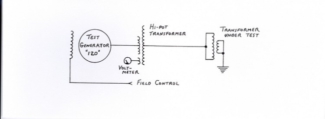
- provide 60-cycle power of good waveshape for hi-pot testing.
In addition, as the use of fans and pumps for the purpose of more efficient cooling of oil-filled transformers became more common, "auxiliary power" to run these devices needed to be supplied by the test power system.
The method involving the use of D.C. drive motors for the test generators so as to enable the generators to produce various frequencies (as described earlier) was employed in the Power Bay installation.
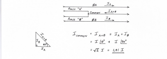
Originally, the Power Bay electrical requirements were supplied by the plant's Power House, via three two-phase, 2300-volt feeders. The distribution system employed was three-wire, with one wire common to the two phases:
This allowed for the use of three-pole (rather than four-pole) devices such as circuit breakers and knife switches. However, since the common wire current was greater than the currents in the other two wires, this meant that there was a certain amount of wasted capacity in two poles of these devices.
The total combined capacity of the three feeders from the Power House was 6000-Kva. However, the total Kva of all of the test generators in the Power Bay was considerably more than this. Part of this discrepancy is explained by the fact that not all of these generators were in use at the same time; but, there is also the consideration of the type of load presented by the transformers being tested.
As discussed earlier, transformers being tested at their normal frequency (for core loss, load loss, and heat runs) appear to the power system as very low power factor loads. Thus, the majority of the load on the test generator is reactive. The corresponding reactive component of current can be supplied by the generator itself; only the real component of current (resulting from the real power losses in the transformer being tested, as well as in the power system itself) need be supplied by the drive motor for the generator. Thus, the total Kva required from the plant power system is much less.
Some of the motor-generator sets in the Power Bay were new in 1917, but many were old sets which had been moved from the test power system in Buildings 1-2-3. Some of those sets, however, remained there so as to provide test power for testing smaller transformers which were still being built in those areas.
As was the accepted practice in the era that the Power Bay was constructed, the switchboards for the control of the many motors and generators were composed of vertical slate panels mounted on pipe frameworks. Along the west wall of the Power Bay, starting from the north end, these switchboards were:
- A.C. Receiving Board
- A.C. Motor Board
- Exciter Board
- D.C. Power Board
- 24/420-cycles Board
- 60-cycle Loader Board
- D.C. Motor Board
In addition, along the east wall of the Power Bay, there were four switchboards (A.C. Generator Boards Nos. 1 through 4) for the control of the individual test generators.
A.C. Receiving Board
The three two-phase, 2300-volt Power House feeders terminated at this switchboard. Breakers on the board controlled the power to the A.C. Motor Board and to the 24/420-cycles Board, for the operation of 2300-volt synchronous drive motors.
Another breaker controlled power to a step-down transformer which, in turn, provided 550-volt two-phase power for smaller induction-type drive motors. There was also a breaker controlling an auto-transformer that provided reduced voltage (900-volts) for starting the large synchronous motors. Finally, a breaker labeled "Power House Direct" provided a tap directly from the Power House feeders for special situations where a large amount of 2300- volt, two-phase power might be needed on a temporary basis.
A.C. Motor Board
This switchboard controlled the starting and running of various 2300-volt synchronous and 550-volt induction drive motors. The synchronous motors drove the Prime Mover D.C. generators, D.C. exciters which fed the Main Exciter Bus (to provide excitation for most of the test generators), and a set of 200-cycle generators used for induced-voltage tests.
The induction motors drove smaller exciters which were used to excite the fields of particular larger test generators, a 60-cycle generator used for hi-pot tests, and a special 125-cycle generator used for certain types of induced testing.
D.C. Power Board
This board controlled the D.C. output of the Prime Mover generators. D.C. power (at five different voltages) was fed from here to the D.C. Motor Board which controlled the D.C. drive motors for the individual test generators.
Some of this D.C. power was also fed back to the Building 1-2-3 complex to operate test generator sets which had remained in use there.
In addition, D.C. power was fed to the 60-cycle Loader Board to operate the D.C. drive motor for the 60-cycle loader (Generator 104).
Exciter Board
All of the various 125-volt D.C. exciters were controlled from this switchboard. There were three main exciters, each of 100-kilowatt capacity, which fed the Main Exciter Bus. There was also a "spare" 60-kilowatt exciter, and six smaller exciters which were used with particular test generators of larger capacity.
From here, D.C. excitation power was sent to the A.C. and D.C. Motor Boards, the four A.C. Generator Boards, the 24/420-cycle Board, the 60-cycle Loader Board, Building 1, and Building 12A (regulator test).
24/420-cycles Board
This switchboard was devoted to the control of the frequency-changer types of motor-generator sets. These sets provided 24-cycle power for loading heat runs on 25-cycle transformers, as well as 420-cycle power for induced-voltage tests. Since most of the machines controlled from this switchboard were for 24-cycle loading, it was sometimes referred to as the "Loader Board".
Around 1930, this switchboard was extensively modified to accommodate the controls for a new 420-cycle generator for induce tests. This was Generator 184, and it continued in use into the 1980's. New panels for control of it, its drive motor, and its exciter were installed in place of the panels for the old 24-cycle loader generators. By this time, bucking heat runs were no longer required in all cases (replaced by the short-circuit type of heat run), so that the need for the old loader generators had diminished.
60-cycle Loader Board
Generator 104 (the 60-cycle loader) and its D.C. drive motor were controlled from this board. Starting switches and resistors were provided for bringing the drive motor up to speed. Even though this machine was referred to as the "60-cycle" loader, the fact that it was equipped with a D.C. drive motor meant that it was capable of producing lower frequencies by controlling the speed of the motor. Thus, it could have replaced the function of the old 24-cycle loaders when they were removed and scrapped around 1930 (see above).
D.C. Motor Board
All but one of the twenty-four D.C. drive motors in the Power Bay were controlled from this board. The exception was the motor for Generator 104 which was controlled from the 60-cycle Loader Board.
A series of horizontally-mounted double-throw knife switches were used for each motor to select one of the five D.C. voltages (220, 275, 330, 440, or 550 volts) for its operation. A clever arrangement of vertical notched hardwood strips prevented the closing of more than one of these switches at a time. If this were
to be done, it would place a dead short circuit across a portion of the main D.C. power busses. The result would no doubt be spectacular!
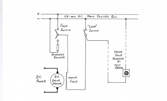
The field circuit of each D.C. drive motor included a "loop" switch. This allowed the control of the motor field to be transferred to a rheostat in the test berth that was using the generator driven by the motor. The test berth operator needed control of the motor field so as to be able to fine-tune the frequency produced by the generator.
The basic circuitry was as shown below:
During start-up of the motor-generator set, the loop switch would be closed so as to be able to start the D.C. motor with a full field. Then, the switch would be opened to transfer field control to the test berth.
A.C. Generator Boards
Four switchboards, controlling a total of thirty-two test generators, were located along the east wall of the Power Bay.
These boards contained circuit breakers, generator field switches, voltmeters, and ammeters. There were also field rheostats on the switchboard panels, but these were not routinely used. As with the D.C. drive motors, the generator fields were capable of being controlled from the test berths. This enabled the berth operator to have control of the generator output voltage which was an essential feature.
With few exceptions, the test generators were rated for 2300-volt, three-phase output. However, in order to obtain greater current capacities (at lower voltages), the windings of the generators were broken up into a number of sections (four, six, or eight). Mounted on pipe frameworks alongside the generators were marble panels (marble instead of slate because of the voltage level involved) containing an array of copper studs. Large copper links were used to interconnect the studs, thus connecting the generator windings in a particular configuration. A framed drawing showed the various connection "diagrams" for each generator. Thus, these panels were often called "link" or "diagram" boards.
For the testing of single-phase transformers, some of these diagrams involved the use of portions of two of the three generator phases. This allowed for even more combinations of voltage and current levels by the vector addition of the individual phase voltages. In some cases, diagrams were used which produced a two-phase output from a three-phase generator by means of the same vector addition process.
For testing which required voltages in excess of 2300 volts, some of the generators were able to be switched through step-up transformers. Thus, these generators could be routed to a particular test berth either "direct" or through its step-up. The step-ups, in turn, usually had their own link boards which were used to connect their winding sections in various configurations in order to increase their flexibility.
In addition, the three-phase banks of step-up transformers could have both their primary and secondary windings connected in either "delta" or "wye" in order to provide even more voltage and current combinations.
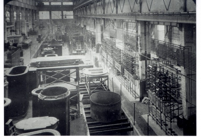
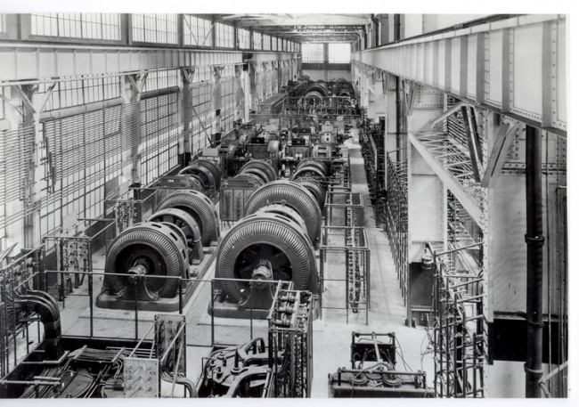
The photograph on the previous page shows the completed Power Bay installation. The switchboards can be seen at the right, with the A.C. Motor Board in the foreground.
The following is from a 1950 Test Manual:
Power Orders
All power switching to the test berth is made by the power plant operators. The test man should use the Power Order slip to request. this service. The following procedure should be used:
(1) Calculate the values of voltage and current needed for the tests to be made.
(2) Go to the Power Order Desk and examine the Power Book for suitable: alternators and transformers which may be switched to your test berth.
(3) Check the Power Board to be sure the equipment desired is not in use. If in doubt, consult the power plant operator.
(4) Fill out the Power Order slip and place it on the operator's desk.
(5) The operator will notify you when the connections are complete. Do not attempt to energize the berth until this notification has been received.
The test berth operators were responsible for determining the voltage and current needed to perform a given test (such as core loss, load loss, or heat run). This information was calculated by using the test instructions as issued by the transformer design engineer.
In addition, Power Order slips would have to be submitted requesting power to run insulation tests; namely, hi-pot and induced-voltage tests.
The appropriate generator would be routed to the particular test berth by means of "Selector Boards", which will be described below.
Power Bay Generators
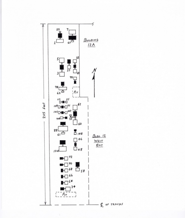
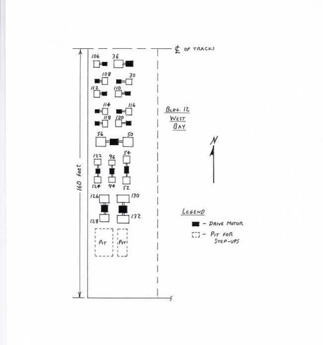
Following is a floor plan of the Power Bay as it originally existed. This was taken from one of a set of old glass projection slides which were found, with the aid of "Pete" Kemp, in an abandoned office on the top floor of Building 5 in the Pittsfield plant. This office had been the base of operations for the Manufacturing Engineering operation in the past. These slides were located in 1985, and dated from 1917 and 1918.
All of the individual generators (and exciters) shown on the floor plan are tabulated in the listing which follows it, starting at the north end of the Power Bay and working south.
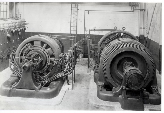
The Prime Mover motor-generator sets (out of view in the previous photo) occupied the extreme north end of the Power Bay. Generators 1 and 7 both provided 550/275 volts D.C. Generators 3 and 5 were used in combination to provide 440/330/220 volts D. C. Each of these was a 220/110 volt generator. Generators 3/5 are seen in the photo, being the large three-unit set at right center in the foreground.
The remaining motor-generator sets in the foreground of the photo are Main Exciter sets. These were all rated for 125-volts D.C.
The exciter set in the very center foreground was a particularly interesting one. The exciter was a generator built by the Crocker-Wheeler Company in the town of Ampere, New Jersey (near East Orange). Most of the machines involved in this installation were, as would be expected, manufactured by General Electric in Schenectady, New York. It so happens that William Stanley often purchased Crocker-Wheeler machines for use as exciters with the alternating current generators manufactured by his company.
The drive motor for this set was, in fact, an old Stanley "inductor" type of two-phase motor. Another interesting feature of this set was that it was able to be used in the reverse mode; that is, the Crocker-Wheeler machine could be used as a D.C. motor driving the Stanley machine as a test generator!
| Generator | Frequency | Function | KVA .(or KW) |
| 1 | DC | Prime Mover | 500 |
| 55 | DC | Exciter for 1 | 10 |
| 7 | DC | Prime Mover | 1000 |
| 67 | DC | Exciter for 7 | 5 |
| 3 | DC | Prime Mover | 200 |
| 5 | DC | Prime Mover | 200 |
| 33 | DC | Main Exciter | 100 |
| 69 | DC | Main Exciter | 100 |
| 99 | DC | Main Exciter | 100 |
| 37 | DC | Spare Exciter | 60 |
| 98 | 420 | Induce Tests | 1300 |
| 65 | DC | Exciter for 98 | 25 |
| 113 | DC | These exciters were used for Generators: 94/96, 112/124, 126/128, and 130/132 | 15 |
| 115 | DC | These exciters were used for Generators: 94/96, 112/124, 126/128, and 130/132 | 15 |
| 109 | DC | These exciters were used for Generators: 94/96, 112/124, 126/128, and 130/132 | 30 |
| 111 | DC | These exciters were used for Generators: 94/96, 112/124, 126/128, and 130/132 | 30 |
| 105 | DC | These exciters were used for Generators: 94/96, 112/124, 126/128, and 130/132 | 30 |
| 107 | DC | These exciters were used for Generators: 94/96, 112/124, 126/128, and 130/132 | 30 |
| 74 | 60 | Hi-pot Tests | 100 |
| 60 | 24 | Loader | 500 |
| 62 | 24 | Loader | 500 |
| 35 | DC | Exciter for 60/62 | 10 |
| 88 | 24 | Loader | 500 |
| 61 | DC | Exciter for 88 | 100 |
| 148 | 125 | Induce Tests | 90 |
| 104 | 25-60 | Loader | 4300 |
| 46 | 200 | Induce Tests | 100 |
| 48 | 200 | Induce Tests | 100 |
| 58 | 25-60 | Magnetizer | 80 |
| 72 | 25-60 | Magnetizer | 200 |
| 70 | 25-60 | Magnetizer | 200 |
| 68 | 25-60 | Magnetizer | 200 |
Generators 1 through 96 were moved to the Power Bay from Building 1, having been used there for quite some years. Generators 98 through 120 were purchased new in 1913 and installed in Building 3; however, just four years later, they were moved to the Power Bay.
Generators 122 through 132 were purchased new for installation in the Power Bay.
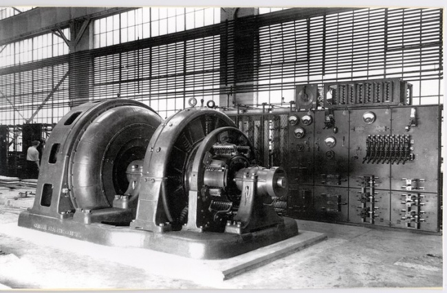
Generators 122/124, along with their 625-horsepower D.C. drive motor, suffered an interesting fate sometime during the mid-1950's.
Contrary to what might be expected, if a D.C. motor loses its field current while the armature remains connected to the D.C. power, it will speed up uncontrollably; this is a consequence of Faraday's Law of Electromagnetic Induction as applied to D.C. motors.
The drive motor for this set had been equipped with an Amplidyne field control around 1953. This allowed for much closer control of motor speed (and, hence, generator frequency) than a simple rheostat manipulated by the test berth operator.
Generators 122/124 were located in the southern half of the Power Bay, while the armature breaker for the drive motor was on the D.C. Motor Board in the northern half. The controls for the Amplidyne, however, were next to the generators.
In order to avoid walking all the way to the northern half of the Power Bay to shut down this set by tripping the armature breaker for the motor, the foreman on the second shift had gotten into the rather unforgiveable habit of simply shutting down the Amplidyne. This would remove the field from the motor causing the motor to speed up. Then, an overspeed device on the end of the shaft of the set would operate and trip the armature breaker on the D.C. Motor Board!
One day, however, the first shift Power Operators had problems with this breaker "hanging up" so that it would not trip. Despite having been warned of this situation, the second shift foreman proceeded to shut down the set using his normal technique. The overspeed device worked, but the breaker stuck and did not trip.
With no field, and with the armature connected to the D.C. power busses, the motor "took off". The photograph on the following page shows the aftermath of this unfortunate series of events.
A 1959 inventory of Power Bay motors and generators lists Generators 122/124 as being "in orbit"
Selector Boards
The Selector Boards were the means by which the power and control connections for the test generators were routed to particular test berths. There was one Selector Board for each berth, twenty-six in all.
The power connections were made by means of a bank of three single-pole disconnect switches, one for each phase of the generator. These switches were mounted one above the other on porcelain insulators, and were operated by means of a long pole from the floor. For each test berth, there were as many banks of switches as there were generators capable of being routed to that berth.
Beneath each bank of disconnect switches, there was a small marble panel containing single-pole knife-type switches and indicating lamps. The switches completed the connections between the rheostats in the test berth and the fields of the test generator and its D.C. drive motor. Thus, control of generator voltage as well as frequency was transferred to the test berth which was using a particular generator. The indicating lamps showed when the associated circuit was complete, and was energized.
Sometimes, an alternate excitation source was available for use with the generator. In these cases, there would be a third knife switch to select this alternate source (in place of the Main Exciter Bus) for the field of the generator.
For generators driven by synchronous motors, there would be no knife switch for motor field control since the motor operated at constant speed. This was the situation for the 24-cycle Loaders and for the generators used for induced-voltage tests.
There was no means for providing an interlocking function as a safeguard against switching two generators into the same test berth. This situation was avoided simply by relying on the competence of both the test berth operators and the Power Operators. It was the responsibility of the berth operators to clear the connections to a generator when testing was done.
Louie Shaw
The original Power Bay installation was of an era in which those who were responsible for operating and maintaining it had to exercise extreme care in order to avoid injury or possible electrocution. This was long before the days of "OSHA" and many of the high voltage electrical connections were exposed, or otherwise quite accessible (such as knife switches on switchboards and bus bars behind the boards).
The death by electrocution of a plant electrician named Louie Shaw, sometime in the 1950's, illustrates this danger. Contrary to normal practice, Shaw had a habit of working alone. He did not return home after working overtime one Saturday during the summer. His wife was not unduly alarmed by this because Shaw had a fondness for betting on the horses, and the racetrack at Saratoga, New York was open!
As it turned out, however, he had not gone to Saratoga. He had spent Saturday afternoon working (alone) on control wiring behind one of the A.C. Generator Boards in the Power Bay. The particular switchboard panels which Shaw was involved with were for the control of Test Generators 126/128, which were located nearby and which were not running. Thus, Shaw assumed that those panels were dead.
What he did not know was that the bus bars behind the panels were being "backfed" from the Big Set in Building 12-Ext. A heat run in a test berth normally served by Generators 126/128 required more power than those generators could provide. Selector switches had been closed in another test berth which effectively connected the bus bars of the Big Set to those behind the Generator 126/128 switchboard panels.
Shaw, of course, was not aware that the Big Set was running and supplying power to the bus bars of the switchboard panel on which he was working. He went behind the switchboard, sat down on the bus bars, and was instantly electrocuted by about 1100 volts. As it turned out, the heat run was shut down very soon after this happened.
When he was missed, his co-workers began a search. Apparently, they passed by the switchboard in question several times, but his body was obscured by storage racks. He had not punched out on the time clock, but that was not unusual for him! Thus, they assumed that he had slipped out and gone to the track.
When he did not return home by Monday morning, his wife became concerned and called the plant. However, in the meantime, the first shift crane operator in the adjacent West Bay of Building 12 had spotted Shaw's body from the cab of his crane. When his co-workers who had searched for him on Saturday realized that they had passed so close to his body and not known it, some of them became so distraught that they went home sick!
Power Bay alterations
As might be expected, the Power Bay installation underwent a great many changes over its nearly seventy year existence. Older machines were gradually scrapped and replaced by newer ones. Some old machines, on the other hand, actually survived until the plant closing in 1987. These had been moved from the Power Bay to Building 100A, the motor-generator building associated with the Test Operation in Building 100.
When Building 100 was being laid out during the 1960's, it became obvious that the northern end of the Power Bay would have to be razed to make room for it. As a result, about sixty feet at the northern end was sacrificed. This necessitated the moving of the Prime Mover and Main Exciter motor-generator sets.
At some time prior to this, the two sets which had included Prime Mover Generators 1 and 3/5 had both been replaced by new sets; the original generator numbers were retained, however. Both of these sets were moved to Building 100A. Of the original Power Bay generator sets, those including Test Generator 116 and 60-cycle Loader Generator 104 were also moved to Building 100A. In addition, the set which included Test Generator 120 was moved to Building 100A at a later time.
By 1984, the Building 12 complex was no longer in use for the assembly and testing of transformers. In order to consolidate facilities, the remaining motor-generator sets and associated switchgear in the Power Bay were scrapped. The floor space in the (former)
Power Bay was then converted for uses associated with the assembly of high voltage porcelain bushings.
Thus ended the existence of a very unique, and extremely interesting, electrical installation.
Chapter 18: Building 100 Test
In 1964, it was recognized that a completely new and much larger transformer assembly and test facility would be needed for the Pittsfield plant to keep up with the demand for ever larger transformers; particularly as regarded "EHV" transformers operating at voltages in excess of 230-kv.
A task force was appointed to evaluate alternatives and, in November of 1965, the Board of Directors of the General Electric Company approved an appropriation in the amount of twenty-seven million dollars for the construction of what would become known as "Building 100". It was decided that the number "100" would be assigned to this building, rather than use the next available number in the Pittsfield plant building numbering sequence, because of its size and significance to the Pittsfield transformer operation.
Due to the size of this project, it was administered by the Real Estate and Construction Operation of the General Electric Company (in Schenectady, NY). The Gilbane Construction Company of Providence, Rhode
Island was selected as the prime contractor. Fishback and Moore of New York City was the prime electrical contractor, and Charles T. Main of Boston was selected as the engineering and architectural firm. C.T. Main had designed Building 12Y, as well as the Sound Test facility (Building 12T).
T.O. ("Tom") Stanfield, of the Pittsfield plant's Manufacturing Engineering operation, was placed in charge of all equipment related to the testing of the transformers built in Building 100. C.T. Main handled the structural designs related to the test facilities in Building 100, the associated motor-generator building (Building 100A), and the outdoor transformer and capacitor installations for the test power system.
They were, however, "overwhelmed" when it came to the design of the intricate circuitry associated with the test power system. As a result, Stanfield was forced to take on this additional responsibility as well.
One major task in the preparations necessary for the construction of Building 100 was the relocation of part of Substation 12. This structure was located adjacent to the north end of the Building 12 Power Bay. It not only supplied power to all of the motor-generator sets in the Power Bay, but it was also a key substation in the over-all Pittsfield plant electrical distribution system.
Since the north end of Building 12 was to be sacrificed to make way for Building 100, the north end of Substation 12 also had to go. There was money available, but not sufficient time, to build a completely new substation. Thus, it was decided to relocate the north end of the structure and attach it to the south end. Fishback and Moore planned the move. Everything was labeled and prepared in advance. Then, everyone simply waited for a weekend with no rain in the forecast so that the operation could be carried out with a minimum of disruption to plant production schedules. The move went off without a hitch and everything was back in operation the following Monday!
The testing of transformers had to continue right through the entire period of construction of the new Building 100. This meant, of course, that the power system for testing had to remain reasonably intact. The plan was that the Building 12 complex would remain in use after Building 100 was completed; it would be used for the assembly and testing of smaller types of transformers.
In Chapter 16, it was mentioned that the Big Set was scrapped at the time of construction of Building 100. Another complication was that Generators 400 and 402 were located in Building 7J, which also had to be razed to make way for the new construction! The only set of 12-Mva test generators which were able to remain undisturbed were Generators 176 and 178 located at the north end of Building 121. In fact, these two generators remained in use at that location through to the closing of the transformer operation in 1987, even though they ended up supplying power only for the test berths in Building 100 after Building 12Y ceased to be used for transformer testing,
Thus, the construction of Building 100A, the new home for test motor-generator sets, had to be carefully scheduled in order to provide a continuity of power for testing purposes. Test generators located in that building were arranged so as to be able to supply power to test berths in Building 12Y as well as Building 100.
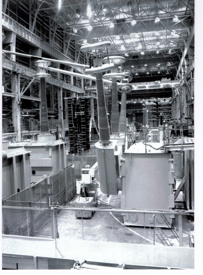
Generators 400/402 were moved from Building 7J to Building 100A (one of them was dropped in the process, but it survived!). A new set of 12-Mva generators was purchased to replace the Big Set. They received the numbers of the scrapped machines which they replaced; that is 172 and 174. This set was also installed in Building 100A. Three older motor-generator sets were also moved to Building 100A from the Building 12 Power Bay, in order to supply power to the Building 12Y test berths. These included a set of 3000-Kva generators with a D.C. drive motor (Generators 180/182), as well as two sets of generators having synchronous drive motors. Each one of these generators was rated at 2000-Kva, and they were known as Generators 200/202 and 204/206. These latter generators fell out of use as testing in Building 12Y was discontinued. Generators 180/182, however, remained in occasional use for testing done in Building 100. This had to do with the fact that they were arranged to produce 50-cycle (and 25-cycle) power in addition to 60-cycles. During the 1980's, transformers were built and tested in Building 100 which were designed for operation at 50-cycles. These units were for Israel Electric and for the Egyptian Electric Authority. Building 100A still exists and is located just to the east of Building.12Y (south of Building 100). To the east of Building 100A, in turn, there was a large installation of capacitor banks used to provide reactive Mva for load loss, tests and heat runs in Building 100. These have, however, been removed. Also removed were the transformers which interfaced the test generators in Building 100A with the test berths in Building 100. These were located outside, between these two buildings. Also installed in Building 100A were two new motor-generator sets to provide power for induced-voltage tests in Building 100. These were frequency-changer sets which produced 240-cycle power. This lower value of induce test frequency was deemed necessary because capacitive effects in very large transformers became a problem when using the old frequency of 420-cycles. Old Generator 184, a 420-cycle machine located in the Building 12 Power Bay, was routed to Building 100, however, for occasional use. This was sometimes necessary when performing series resonant "induce" tests on high voltage shunt reactors. Generator 184 was last used for this purpose in 1983.
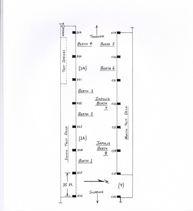
Building 100 itself was arranged so that the flow of transformers being built was from west to east. The transformer cores entered from the west end, having been assembled in Building 3. Some very large cores were, however, assembled on a large core cradle (sometimes referred to as the "Jolly Green Giant" because of its color) at the west end of Building 100. The cradle was then manipulated via the large overhead cranes to turn the core to an upright position. There was also a core, cradle built into the floor at the north end of Building 3 for the same purpose. Core steel came from the area to the west in Building 15. In later years, this steel was fabricated by the state-of-the-art GEORG core steel processing machine located there. The transformer windings also entered Building 100 near the west end. The windings came either from the main Winding Room in Building 17, or from newer winding lathes which had been installed in Building 1. Then, the windings were "landed" on the cores, again using the overhead cranes and a lifting device known as the "Big Yellow Bird" (again because of its color). The resulting core-and-coil assemblies were cabled and made ready for the vacuum treat tanks along the southern wall of the building. Following vacuum treat, the assemblies were stored in Dry Rooms located just east of the vacuum tanks. The transformer tanks entered Building 100 via a door on the north side, about midway along the length of the building. These steel tanks were fabricated in the Tank Shop (Building 14) just to the north of Building 100. The Tanking Area in Building 100, where the core-and-coil assemblies were lowered into their tanks, occupied the main floor area east of the Dry Rooms. The main building columns along the north and south sides of Building 100, which supported the rails for the overhead cranes, were numbered from west to east. There were thirty-three in all (and still are, since Building 100 still stands), and the Test Operation occupied the main floor area between Column 19 and Column 26. This was to the east of the Tanking Area. Finally, east of Test was the Shipping Area. There, the transformers were placed on railroad cars (occasionally on trucks); sidings ran into the east end of the building and connected with the main line of Conrail, which runs east and west through the plant. There were two levels of overhead cranes in Building 100. In addition, there were gantry cranes and jib cranes located throughout the building to serve specific
areas and functions. The overhead cranes were built by the Whiting Company, and were all remotely-controlled from boxes carried by the crane operators on the floor. There were two levels of cranes: the lower level consisted of four 25-ton capacity cranes with 5-ton auxiliary hooks, and the upper level consisted of two 350- ton capacity cranes. The lower cranes were numbered "1" through "4", while the upper cranes were designated as "A" and "B". The capacity of the two upper cranes had to do with the fact that completely assembled, oil-filled transformers had to be lifted into and out of the test berths. For the heaviest transformers, both cranes were used together ("two-crane lift") to lift a maximum weight of 700 tons. Normally, eight steel cables, each of two inches diameter, were used to lift 350 tons. Sometimes, in order to obtain the maximum capacity from the steel cables, or to avoid damaging porcelain bushings on the transformer being lifted, large units known as "lifting beams" or "spreaders" were used in order to keep all of the cables vertical. The largest of these was rated at 700-tons and was built by the American Forge and Manufacturing Company; it was one of the largest such units ever built at the time. There were also two smaller lifting beams, each rated at 350 tons. Each lifting beam was equipped with two hooks which could be positioned by electric motors within the beams for the correct spread. This was done before the beam was lifted in the air by the crane hook. Because of the multiple sheave cabling of the hooks on the 350-ton cranes, the hooks normally operated at a fairly low speed (less than nine feet per minute). An innovation was included in the control system for these cranes which allowed the hooks to be raised at a speed of fifty feet per minute when they were empty. This saved a great deal of time since the distance which these hooks had to travel was nearly one hundred feet! The layout of the Building 100 Test operation was as shown on the previous page. The two test decks were elevated about twelve feet above the main floor of the building and served as the main operating level. The control consoles were located on the decks; these were for the control of A.C. test power and for the measurement of volts, amps, and watts. There were six such berths (called "60-cycle" berths); Berths 1 through 4 were on the south side, while Berths 5 and 6 were on the north side.
While the north Test Deck did extend over Impulse Test Berths 7 and 8, it was not used; the controls for the impulse generators, and the measurement oscilloscopes, were located at the main floor level. This had to do with the need for frequent access to the impulse generators themselves to change internal connections. Access to transformers being tested in the 60-cycle berths was via ramps leading from the Test Deck to the tops of the transformers. In this respect, these berths resembled the old pit test berths in the Building 12 complex. Test men who were trained in the operation of these berths were referred to as "Pit Testers" because of this similarity. "Impulse Testers" were test men who had received additional training in the specialized area of impulse testing; these men were also paid more! Each 60-cycle berth was equipped with either one three-phase transformer or three single-phase transformers, known as "matching" transformers. These were all equipped with winding taps, series-multiple connections, and delta-wye switches which provided a great variety of transformer ratios. Thus, for each particular test situation, the berth requirements could be "matched" to the output of the test generator. For Berths 1 through 4, these transformers were outside along the south side of Building 100; for Berth 5 and 6, however, they were inside (behind the north Test Deck). High voltage busses running along the next level above the Test Decks functioned to connect the outputs. of the matching transformers to long, heavy, flexible cables which hung down along the edges of the decks. These cables were used to make the temporary test connections to the transformers being tested. Many years before Building 100 was built, these cables had come to be known as "Magi's". This nomenclature resulted from the fact that their primary function was to supply magnetizing current to the transformer under test. This is sometimes referred to as Mag-I. Also on this upper level were current transformers and capacitive coupling devices for the measurement of current and voltage, respectively. The current measurement devices were Zero-Flux C.T.'s, one in each of the three phases, capable of handling currents as high as 3000 amperes. The voltage capabilities of the test berths varied from berth to berth; the highest voltage available (in Berths 1 and 2) was 240-kv. The capacitive voltage measurement devices in each berth were connected from each phase to ground.
In addition to these measurement devices, there were motor-operated disconnect switches and safety grounding switches to disconnect and ground the Magi's whenever the test men had to change electrical connections in the berth.
A set of Magi's and disconnect switches were loc-ated in the space between Berths 1 and 2. This area was referred to as Berth "lA", and it received power from old Generator 184 in the Building 12 Power Bay. This was a 420-cycle induce test generator, and was occasionally used for insulation tests on high voltage shunt reactors in Building 100.
Likewise, a set of Magi's and disconnects were located in the space between Berths 3 and 4. This was referred to as Berth "3A" and received power from old Generator 104 (the "60-cycle Loader") which had been moved from Building 12 to Building 100A. It turned out that this generator was useful for supplying power for "zero sequence" tests on transformers. In this type of test, all three phases of a three-phase transformer are connected together and single-phase voltage is applied between the common connection and ground. The voltage and current are measured in order to determine the resulting zero sequence impedance. This impedance is very useful to power system engineers in determining the behavior of the transformer during short circuit conditions on the power system.
Power for hi-pot tests was available in all six of the main 60-cycle berths. Usually, this power came from a motor-operated induction-type voltage regulator located in Building 100A. Sometimes, however, hi-pot test conditions required the use of old Generator 120 which had also been moved from Building 12 to Building 100A. This generator had a very good sine wave output and, thus, was suitable for hi-pot testing.
In addition, all of these berths had "auxiliary" power available for running fans and oil pumps on units which had forced cooling. Since virtually all of the transformers tested in Building 100 were designed for use on 60-cycle power, this auxiliary power was simply taken from the plant power system (at 240 or 480 volts). Old Generator 116 from the Building 12 Power Bay had been moved to Building 100A with the intention of using it to supply auxiliary power for units which might be designed for 25-cycle or 50-cycle operation (it had a D.C. drive motor). However, there was never any great need for this and, as a result, Generator 116 was never even connected for operation in Building 100A!
Impulse Test
Impulse Test Berth 7 was equipped with a 3000-kv impulse generator of the "World's Fair" design; this generator had been moved to Building 100 from either Building 12X or 12Y. Another similar generator from those buildings was installed in a bay on the north side of Building 100 Test which was called Berth 9. Berth 8 was equipped with a 4200-kv impulse generator built by the Haefely Company of Switzerland. All of these generators were mounted on electrically-powered cars which ran on tracks in the floor of the building. Thus, they could be positioned optimally in order to accommodate various sizes of transformers.
The Haefely impulse generator towered to within a few feet of the lower set of overhead cranes. A horn was routinely used to warn of the impending discharge of the impulse generators during testing. Sometimes, however, this warning system failed. Either the impulse test operator would forget to sound the horn, or the crane operators would ignore it. Once in a while, if one of these cranes was directly over the Haefely generator when it should not have been, the discharge might flash to the crane!
This posed no danger to the crane operator, who would be controlling the crane remotely from the floor; however, it "raised hell" with the electronic control equipment on the crane itself! When this occurred, it usually put the crane out of service for some time until the crane service personnel could replace burned circuit cards in the control cabinets. Naturally, a great deal of "finger-pointing" would occur when this happened, both because of the cost of repairing the crane and because of the disruption to production which it caused.
The routine means of determining whether a transformer had passed the impulse test series was inspection of the resulting oscillograms for discrepancies in waveform. However, Jim Heil of Building 100 Test was instrumental in developing a means of detecting sonic vibrations through the oil in the transformer. Pick-up devices attached to the outside of the tank would sense such disturbances. This technique was very sensitive; there were situations when comparison of the before and after test oscillograms showed no real indication of a failure. However, unusual displays on the oscilloscope for the sonic probes did!
Series resonant tests
One of the more exotic types of testing performed in Building 100 involved the "induce" testing of high voltage shunt reactors. The term "induce" as used here is a misnomer since reactors have only one winding. Thus, test voltage cannot be induced from one winding to another as with transformers. The term came to be used simply because this test stressed the turn-to-turn insulation in the reactor winding, just as a true induce test does in a transformer.
Since the high value of voltage required for such a test could not be induced from a winding of lower voltage rating, some means had to be devised to produce this voltage (as much as several hundreds of kilovolts). The use of a series resonant circuit was the solution.
Originally, capacitor stacks were designed which could be used to resonate with the inductance of the reactor winding to create much higher voltages than could be generated directly. The capacitance used was such that 420-cycles was required to energize the test. circuit. Thus, Generator 184 (Via Berth "lA") was used as a source of power. Eventually, however, even though the capacitor stacks had been designed to be relatively corona free, this became a problem at higher test voltages.
Thus, oil-filled capacitor tanks were designed to replace the stacks. The capacitance values used for these tanks were such that the new 240-cycle induce, test generators could be used instead of Generator 184. For testing three-phase shunt reactors, a technique was devised using both capacitor tanks to create a doubly-resonant circuit. One reactor phase would be tested at a time; the other two phases were maintained at a voltage level equal to one-half of that of the phase under test.
Jim Heil was responsible for developing each particular test set-up. This was a rather tedious undertaking since "playing around" with a series resonant circuit at these high voltage levels can produce some hair-raising situations if things go wrong!
The three-phase resonant circuit was designed so that tuning of the circuit was possible by means of capacitor cans external to the tanks themselves; these external cans remained close to ground potential during the test itself.
Control of test power
The control of power from the test generators in Building 100A to the test berths in Building 100 was via a complex switchboard panel located on the second floor of Building 100A. The generators needed for the particular tests would be started up by the Test Foreman for that shift, and would then be routed to the proper test berths. All of this was done at this control panel. Unfortunately, no provision had been made for an enclosed walkway to connect this panel with the Test Deck in Building 100. This was a decided inconvenience in wintertime, since it was often necessary to make several trips back and forth in one shift!
The Building 100A generator control panel was referred to as the "Chamblee Panel", This resulted from the fact that it had been custom-built by the General Electric switchboard operation located in the town of Chamblee, Georgia. Leadership for the design of this extremely complex panel was provided by Tom Stanfield. His first task was to convince the engineers at the plant in Chamblee that it could be built at all! This was because it had to include a tremendously complex system of electrical interlocking logic for personnel safety, as well as for protection of the equipment. Ultimately, this function was provided by circuitry which used over seven hundred electrical relays! Tom was assisted in this endeavor by "Pete" Kemp of the Test Department.
This panel controlled the starting of all of the Building 100A motor-generator sets. Many of these were old sets which had been moved from the Building 12 Power Bay installation. New sets purchased for use in Building 100A included:
- new Generators 172/174 to replace the scrapped Big Set
- two new 240-cycle induce test generators, numbered 504 and 506
- a small 400-cycle generator. ("150") used for insulation tests on current transformers (C.T.'s) which were an integral part of large power transformers
In addition, it controlled the routing of all generators, as well as ten capacitor banks ("A" through "J"), to the Building 100 test berths.
Chamblee Panel functions
(from left to right)
- – routing of Gens. 400/402 to Berths 1, 2, 4
- - routing of Gens. 176/178 to Berths 2, 3
- - routing of Gens. 172/174 to Berths 1, 3, 5
- - routing of Gens. 180/182 to Berths 4, 5, and 12Y
- - routing of Gens. 200/202 to Berths 6 and 12Y
- - routing of Gens. 204/206 to Berths 6 and 12Y
- - routing of Gens. 504,506 to Berths 1-6 and 12Y
- - routing of Gens. 104,116 1-6 to Berths “3A” and 1-6
- - routing of Gens. 120 & 150 to Berths 1-6
- - routing of Gens. Capacitor Banks A, B, C, D, E, F
- - routing of Gens. Capacitor Banks D, G, H, I, J
- - control of voltage output of Gens. 1 and 3/5
- - starting of drive motor for Gens. 400/402
- - starting of drive motor for Gens. 176/178
- - starting of drive motor for Gens. 172/174
- - starting of drive motor for Gens. 200/202 and 204/206
- - starting of drive motor for Gens. 1 and 3/5
- - starting of drive motor for Gens. 504 and 506
- - starting of drive motor for Gens. 104 and 180/182
- - starting of drive motor for Gens. 116, 120, and 150
Note: "12Y" refers to test berths still in use in Building 12Y.
The starting of most of the motor-generator sets was straightforward; the exceptions were the 12-Mva sets (172/174, 176/178, and 400/402). These sets were equipped with 5000-horsepower synchronous drive motors which were not arranged to be self-starting. Instead, these sets were equipped with 1000-horsepower wound-rotor induction motors which acted as start motors to bring the sets up to speed. This took anywhere from about three minutes to almost ten minutes, depending on the time of year (that is, how cold the oil was in the bearings of the machines!).
When the set was nearly up to speed, the field of the synchronous motor would be energized. At this point, the drive motor was actually acting as an A.C. generator. Its voltage would be adjusted to match the voltage of the plant power system. Then, a device known as a "synchroscope" would be used to determine when the motor voltage was in phase with the power system voltage. At that time, the motor breaker would be closed, and the motor was then "on-line".
The synchroscope rotated like a clock; the twelve o'clock position was the proper indication for the closing of the breaker. If, for some reason, the breaker was to be closed with the synchroscope at the six o'clock position, all hell would break loose. At that point, the motor and system voltages would be completely out of phase, and a massive short circuit would result!
H.H. ("Red") Brustle was in charge of the Building 100 test equipment and power system. Red had terrible sinus problems. Once, he went to Building 100A to start one of the 12-Mva sets. He had his hand on the drive motor breaker control and was watching the synchroscope slowly rotating towards the twelve o'clock position. Suddenly, he sneezed uncontrollably, his hand flinched, and he inadvertently closed the breaker!
Later, he said that it sounded like the building was going to fall down around him! Fortunately, he had closed the breaker when the synchroscope was not at the six o'clock position, but was on the way up to twelve o'clock. Thus, the out-of-phase condition was not as severe as it could have been; no damage was done to the motor-generator set.
Chapter 18: Building 100 Test
In 1964, it was recognized that a completely new and much larger transformer assembly and test facility would be needed for the Pittsfield plant to keep up with the demand for ever larger transformers; particularly as regarded "EHV" transformers operating at voltages in excess of 230-kv.
A task force was appointed to evaluate alternatives and, in November of 1965, the Board of Directors of the General Electric Company approved an appropriation in the amount of twenty-seven million dollars for the construction of what would become known as "Building 100". It was decided that the number "100" would be assigned to this building, rather than use the next available number in the Pittsfield plant building numbering sequence, because of its size and significance to the Pittsfield transformer operation.
Due to the size of this project, it was administered by the Real Estate and Construction Operation of the General Electric Company (in Schenectady, NY). The Gilbane Construction Company of Providence, Rhode
Island was selected as the prime contractor. Fishback and Moore of New York City was the prime electrical contractor, and Charles T. Main of Boston was selected as the engineering and architectural firm. C.T. Main had designed Building 12Y, as well as the Sound Test facility (Building 12T).
T.O. ("Tom") Stanfield, of the Pittsfield plant's Manufacturing Engineering operation, was placed in charge of all equipment related to the testing of the transformers built in Building 100. C.T. Main handled the structural designs related to the test facilities in Building 100, the associated motor-generator building (Building 100A), and the outdoor transformer and capacitor installations for the test power system.
They were, however, "overwhelmed" when it came to the design of the intricate circuitry associated with the test power system. As a result, Stanfield was forced to take on this additional responsibility as well.
One major task in the preparations necessary for the construction of Building 100 was the relocation of part of Substation 12. This structure was located adjacent to the north end of the Building 12 Power Bay. It not only supplied power to all of the motor-generator sets in the Power Bay, but it was also a key substation in the over-all Pittsfield plant electrical distribution system.
Since the north end of Building 12 was to be sacrificed to make way for Building 100, the north end of Substation 12 also had to go. There was money avail-able, but not sufficient time, to build a completely new substation. Thus, it was decided to relocate the north end of the structure and attach it to the south end. Fishback and Moore planned the move. Everything was labeled and prepared in advance. Then, everyone simply waited for a weekend with no rain in the forecast so that the operation could be carried out with a minimum of disruption to plant production schedules. The move went off without a hitch and everything was back in operation the following Monday!
The testing of transformers had to continue right through the entire period of construction of the new Building 100. This meant, of course, that the power system for testing had to remain reasonably intact. The plan was that the Building 12 complex would remain in use after Building 100 was completed; it would be used for the assembly and testing of smaller types of transformers.
In Chapter 16, it was mentioned that the Big Set was scrapped at the time of construction of Building 100. Another complication was that Generators 400 and 402 were located in Building 7J, which also had to be razed to make way for the new construction! The only set of 12-Mva test generators which were able to remain undisturbed were Generators 176 and 178 located at the north end of Building 121. In fact, these two generators remained in use at that location through to the closing of the transformer operation in 1987, even though they ended up supplying power only for the test berths in Building 100 after Building 12Y ceased to be used for transformer testing,
Thus, the construction of Building 100A, the new home for test motor-generator sets, had to be carefully scheduled in order to provide a continuity of power for testing purposes. Test generators located in that building were arranged so as to be able to supply power to test berths in Building 12Y as well as Building 100.
Generators 400/402 were moved from Building 7J to Building 100A (one of them was dropped in the process, but it survived!). A new set of 12-Mva generators was purchased to replace the Big Set. They received the numbers of the scrapped machines which they replaced; that is 172 and 174. This set was also installed in Building 100A. Three older motor-generator sets were also moved to Building 100A from the Building 12 Power Bay, in order to supply power to the Building 12Y test berths. These included a set of 3000-Kva generators with a D.C. drive motor (Generators 180/182), as well as two sets of generators having synchronous drive motors. Each one of these generators was rated at 2000-Kva, and they were known as Generators 200/202 and 204/206. These latter generators fell out of use as testing in Building 12Y was discontinued. Generators 180/182, however, remained in occasional use for testing done in Building 100. This had to do with the fact that they were arranged to produce 50-cycle (and 25-cycle) power in addition to 60-cycles. During the 1980's, transformers were built and tested in Building 100 which were designed for operation at 50-cycles. These units were for Israel Electric and for the Egyptian Electric Authority. Building 100A still exists and is located just to the east of Building.12Y (south of Building 100). To the east of Building 100A, in turn, there was a large installation of capacitor banks used to provide reactive Mva for load loss, tests and heat runs in Building 100. These have, however, been removed. Also removed were the transformers which interfaced the test generators in Building 100A with the test berths in Building 100. These were located outside, between these two buildings. Also installed in Building 100A were two new motor-generator sets to provide power for induced-voltage tests in Building 100. These were frequency-changer sets which produced 240-cycle power. This lower value of induce test frequency was deemed necessary because capacitive effects in very large transformers became a problem when using the old frequency of 420-cycles. Old Generator 184, a 420-cycle machine located in the Building 12 Power Bay, was routed to Building 100, however, for occasional use. This was sometimes necessary when performing series resonant "induce" tests on high voltage shunt reactors. Generator 184 was last used for this purpose in 1983.
Building 100 itself was arranged so that the flow of transformers being built was from west to east. The transformer cores entered from the west end, having been assembled in Building 3. Some very large cores were, however, assembled on a large core cradle (sometimes referred to as the "Jolly Green Giant" because of its color) at the west end of Building 100. The cradle was then manipulated via the large overhead cranes to turn the core to an upright position. There was also a core, cradle built into the floor at the north end of Building 3 for the same purpose. Core steel came from the area to the west in Building 15. In later years, this steel was fabricated by the state-of-the-art GEORG core steel processing machine located there. The transformer windings also entered Building 100 near the west end. The windings came either from the main Winding Room in Building 17, or from newer winding lathes which had been installed in Building 1. Then, the windings were "landed" on the cores, again using the overhead cranes and a lifting device known as the "Big Yellow Bird" (again because of its color). The resulting core-and-coil assemblies were cabled and made ready for the vacuum treat tanks along the southern wall of the building. Following vacuum treat, the assemblies were stored in Dry Rooms located just east of the vacuum tanks. The transformer tanks entered Building 100 via a door on the north side, about midway along the length of the building. These steel tanks were fabricated in the Tank Shop (Building 14) just to the north of Building 100. The Tanking Area in Building 100, where the core-andcoil assemblies were lowered into their tanks, occupied the main floor area east of the Dry Rooms. The main building columns along the north and south sides of Building 100, which supported the rails for the overhead cranes, were numbered from west to east. There •were thirty-three in all (and still are, since Building 100 still stands), and the Test Operation occupied the main floor area between Column 19 and Column 26. This was to the east of the Tanking Area. Finally, east of Test was the Shipping Area. There, the transformers were placed on railroad cars (occasionally on trucks); sidings ran into the east end of the building and connected with the main line of Conrail, which runs east and west through the plant. There were two levels of overhead cranes in Building 100. In addition, there were gantry cranes and jib cranes located throughout the building to serve specific
areas and functions. The overhead cranes were built by the Whiting Company, and were all remotely-controlled from boxes carried by the crane operators on the floor. There were two levels of cranes: the lower level consisted of four 25-ton capacity cranes with 5-ton auxiliary hooks, and the upper level consisted of two 350- ton capacity cranes. The lower cranes were numbered "1" through "4", while the upper cranes were designated as "A" and "B". The capacity of the two upper cranes had to do with the fact that completely assembled, oil-filled transformers had to be lifted into and out of the test berths. For the heaviest transformers, both cranes were used together ("two-crane lift") to lift a maximum weight of 700 tons. Normally, eight steel cables, each of two inches diameter, were used to lift 350 tons. Sometimes, in order to obtain the maximum capacity from the steel cables, or to avoid damaging porcelain bushings on the transformer being lifted, large units known as "lifting beams" or "spreaders" were used in order to keep all of the cables vertical. The largest of these was rated at 700-tons and was built by the American Forge and Manufacturing Company; it was one of the largest such units ever built at the time. There were also two smaller lifting beams, each rated at 350 tons. Each lifting beam was equipped with two hooks which could be positioned by electric motors within the beams for the correct spread. This was done before the beam was lifted in the air by the crane hook. Because of the multiple sheave cabling of the hooks on the 350-ton cranes, the hooks normally operated at a fairly low speed (less than nine feet per minute). An innovation was included in the control system for these cranes which allowed the hooks to be raised at a speed of fifty feet per minute when they were empty. This saved a great deal of time since the distance which these hooks had to travel was nearly one hundred feet! The layout of the Building 100 Test operation was as shown on the previous page. The two test decks were elevated about twelve feet above the main floor of the building and served as the main operating level. The control consoles were located on the decks; these were for the control of A.C. test power and for the measurement of volts, amps, and watts. There were six such berths (called "60-cycle" berths); Berths 1 through 4 were on the south side, while Berths 5 and 6 were on the north side.
While the north Test Deck did extend over Impulse Test Berths 7 and 8, it was not used; the controls for the impulse generators, and the measurement oscilloscopes, were located at the main floor level. This had to do with the need for frequent access to the impulse generators themselves to change internal connections. Access to transformers being tested in the 60-cycle berths was via ramps leading from the Test Deck to the tops of the transformers. In this respect, these berths resembled the old pit test berths in the Building 12 complex. Test men who were trained in the operation of these berths were referred to as "Pit Testers" because of this similarity. "Impulse Testers" were test men who had received additional training in the specialized area of impulse testing; these men were also paid more! Each 60-cycle berth was equipped with either one three-phase transformer or three single-phase transformers, known as "matching" transformers. These were all equipped with winding taps, series-multiple connections, and delta-wye switches which provided a great variety of transformer ratios. Thus, for each particular test situation, the berth requirements could be "matched" to the output of the test generator. For Berths 1 through 4, these transformers were outside along the south side of Building 100; for Berth 5 and 6, however, they were inside (behind the north Test Deck). High voltage busses running along the next level above the Test Decks functioned to connect the outputs. of the matching transformers to long, heavy, flexible cables which hung down along the edges of the decks. These cables were used to make the temporary test connections to the transformers being tested. Many years before Building 100 was built, these cables had come to be known as "Magi's". This nomenclature resulted from the fact that their primary function was to supply magnetizing current to the transformer under test. This is sometimes referred to as Mag-I. Also on this upper level were current transformers and capacitive coupling devices for the measurement of current and voltage, respectively. The current measurement devices were Zero-Flux C.T.'s, one in each of the three phases, capable of handling currents as high as 3000 amperes. The voltage capabilities of the test berths varied from berth to berth; the highest voltage available (in Berths 1 and 2) was 240-kv. The capacitive voltage measurement devices in each berth were connected from each phase to ground.
In addition to these measurement devices, there were motor-operated disconnect switches and safety grounding switches to disconnect and ground the Magi's whenever the test men had to change electrical connections in the berth.
A set of Magi's and disconnect switches were loc-ated in the space between Berths 1 and 2. This area was referred to as Berth "lA", and it received power from old Generator 184 in the Building 12 Power Bay. This was a 420-cycle induce test generator, and was occasionally used for insulation tests on high voltage shunt reactors in Building 100.
Likewise, a set of Magi's and disconnects were located in the space between Berths 3 and 4. This was referred to as Berth "3A" and received power from old Generator 104 (the "60-cycle Loader") which had been moved from Building 12 to Building 100A. It turned out that this generator was useful for supplying power for "zero sequence" tests on transformers. In this type of test, all three phases of a three-phase transformer are connected together and single-phase voltage is applied between the common connection and ground. The voltage and current are measured in order to determine the resulting zero sequence impedance. This impedance is very useful to power system engineers in determining the behavior of the transformer during short circuit conditions on the power system.
Power for hi-pot tests was available in all six of the main 60-cycle berths. Usually, this power came from a motor-operated induction-type voltage regulator located in Building 100A. Sometimes, however, hi-pot test conditions required the use of old Generator 120 which had also been moved from Building 12 to Building 100A. This generator had a very good sine wave output and, thus, was suitable for hi-pot testing.
In addition, all of these berths had "auxiliary" power available for running fans and oil pumps on units which had forced cooling. Since virtually all of the transformers tested in Building 100 were designed for use on 60-cycle power, this auxiliary power was simply taken from the plant power system (at 240 or 480 volts). Old Generator 116 from the Building 12 Power Bay had been moved to Building 100A with the intention of using it to supply auxiliary power for units which might be designed for 25-cycle or 50-cycle operation (it had a D.C. drive motor). However, there was never any great need for this and, as a result, Generator 116 was never even connected for operation in Building 100A!
Impulse Test
Impulse Test Berth 7 was equipped with a 3000-kv impulse generator of the "World's Fair" design; this generator had been moved to Building 100 from either Building 12X or 12Y. Another similar generator from those buildings was installed in a bay on the north side of Building 100 Test which was called Berth 9. Berth 8 was equipped with a 4200-kv impulse generator built by the Haefely Company of Switzerland. All of these generators were mounted on electrically-powered cars which ran on tracks in the floor of the building. Thus, they could be positioned optimally in order to accommodate various sizes of transformers.
The Haefely impulse generator towered to within a few feet of the lower set of overhead cranes. A horn was routinely used to warn of the impending discharge of the impulse generators during testing. Sometimes, however, this warning system failed. Either the im- pulse test operator would forget to sound the horn, or the crane operators would ignore it. Once in a while, if one of these cranes was directly over the Haefely generator when it should not have been, the discharge might flash to the crane!
This posed no danger to the crane operator, who would be controlling the crane remotely from the floor; however, it "raised hell" with the electronic control equipment on the crane itself! When this occurred, it usually put the crane out of service for some time until the crane service personnel could replace burned circuit cards in the control cabinets. Naturally, a great deal of "finger-pointing" would occur when this happened, both because of the cost of repairing the crane and because of the disruption to production which it caused.
The routine means of determining whether a transformer had passed the impulse test series was inspection of the resulting oscillograms for discrepancies in waveform. However, Jim Heil of Building 100 Test was instrumental in developing a means of detecting sonic vibrations through the oil in the transformer. Pick-up devices attached to the outside of the tank would sense such disturbances. This technique was very sensitive; there were situations when comparison of the before and after test oscillograms showed no real indication of a failure. However, unusual displays on the oscilloscope for the sonic probes did!
Series resonant tests
One of the more exotic types of testing performed in Building 100 involved the "induce" testing of high voltage shunt reactors. The term "induce" as used here is a misnomer since reactors have only one winding. Thus, test voltage cannot be induced from one winding to another as with transformers. The term came to be used simply because this test stressed the turn-to-turn insulation in the reactor winding, just as a true induce test does in a transformer.
Since the high value of voltage required for such a test could not be induced from a winding of lower
voltage rating, some means had to be devised to produce this voltage (as much as several hundreds of kilovolts). The use of a series resonant circuit was the solution.
Originally, capacitor stacks were designed which could be used to resonate with the inductance of the reactor winding to create much higher voltages than could be generated directly. The capacitance used was such that 420-cycles was required to energize the test. circuit. Thus, Generator 184 (Via Berth "lA") was used as a source of power. Eventually, however, even though the capacitor stacks had been designed to be relatively corona free, this became a problem at higher test voltages.
Thus, oil-filled capacitor tanks were designed to replace the stacks. The capacitance values used for these tanks were such that the new 240-cycle induce, test generators could be used instead of Generator 184. For testing three-phase shunt reactors, a technique was devised using both capacitor tanks to create a doubly-resonant circuit. One reactor phase would be tested at a time; the other two phases were maintained at a voltage level equal to one-half of that of the phase under test.
Jim Heil was responsible for developing each particular test set-up. This was a rather tedious undertaking since "playing around" with a series resonant circuit at these high voltage levels can produce some hair-raising situations if things go wrong!
The three-phase resonant circuit was designed so that tuning of the circuit was possible by means of capacitor cans external to the tanks themselves; these external cans remained close to ground potential during the test itself.
Control of test power
The control of power from the test generators in Building 100A to the test berths in Building 100 was via a complex switchboard panel located on the second floor of Building 100A. The generators needed for the particular tests would be started up by the Test Foreman for that shift, and would then be routed to the proper test berths. All of this was done at this control panel. Unfortunately, no provision had been made for an enclosed walkway to connect this panel with the Test Deck in Building 100. This was a decided inconvenience in wintertime, since it was often necessary to make several trips back and forth in one shift!
The Building 100A generator control panel was referred to as the "Chamblee Panel", This resulted from the fact that it had been custom-built by the General Electric switchboard operation located in the town of Chamblee, Georgia. Leadership for the design of this extremely complex panel was provided by Tom Stanfield. His first task was to convince the engineers at the plant in Chamblee that it could be built at all! This was because it had to include a tremendously complex system of electrical interlocking logic for personnel safety, as well as for protection of the equipment. Ultimately, this function was provided by circuitry which used over seven hundred electrical relays! Tom was assisted in this endeavor by "Pete" Kemp of the Test Department.
This panel controlled the starting of all of the Building 100A motor-generator sets. Many of these were old sets which had been moved from the Building 12 Power Bay installation. New sets purchased for use in Building 100A included:
- new Generators 172/174 to replace the scrapped Big Set
- two new 240-cycle induce test generators, numbered 504 and 506
- a small 400-cycle generator. ("150") used for insulation tests on current transformers (C.T.'s) which were an integral part of large power transformers
In addition, it controlled the routing of all generators, as well as ten capacitor banks ("A" through "J"), to the Building 100 test berths.
Chamblee Panel functions
(from left to right)
- – routing of Gens. 400/402 to Berths 1, 2, 4
- - routing of Gens. 176/178 to Berths 2, 3
- - routing of Gens. 172/174 to Berths 1, 3, 5
- - routing of Gens. 180/182 to Berths 4, 5, & 12Y
- - routing of Gens. 200/202 to Berths 6 & 12Y
- - routing of Gens. 204/206 to Berths 6 & 12Y
- - routing of Gens. 504,506 to Berths 1-6 & 12Y
- - routing of Gens. 104,116 1-6 to Berths “3A” & 1-6
- - routing of Gens. 120 & 150 to Berths 1-6
- - routing of Gens. Capacitor Banks A, B, C, D, E, F
- - routing of Gens. Capacitor Banks D, G, H, I, J
- - control of voltage output of Gens. 1 & 3/5
- - starting of drive motor for Gens. 400/402
- - starting of drive motor for Gens. 176/178
- - starting of drive motor for Gens. 172/174
- - starting of drive motor for Gens. 200/202 & 204/206
- - starting of drive motor for Gens. 1 & 3/5
- - starting of drive motor for Gens. 504 &506
- 19 - starting of drive motor for Gens. 104 & 180/182
- 20 - starting of drive motor for Gens. 116, 120, & 150
Note: "12Y" refers to test berths still in use in Building 12Y.
The starting of most of the motor-generator sets was straightforward; the exceptions were the 12-Mva sets (172/174, 176/178, and 400/402). These sets were equipped with 5000-horsepower synchronous drive motors which were not arranged to be self-starting. Instead, these sets were equipped with 1000-horsepower wound-rotor induction motors which acted as start motors to bring the sets up to speed. This took anywhere from about three minutes to almost ten minutes, depending on the time of year (that is, how cold the oil was in the bearings of the machines!).
When the set was nearly up to speed, the field of the synchronous motor would be energized. At this point, the drive motor was actually acting as an A.C. generator. Its voltage would be adjusted to match the voltage of the plant power system. Then, a device known as a "synchroscope" would be used to determine when the motor voltage was in phase with the power system voltage. At that time, the motor breaker would be closed, and the motor was then "on-line".
The synchroscope rotated like a clock; the twelve o'clock position was the proper indication for the closing of the breaker. If, for some reason, the breaker was to be closed with the synchroscope at the six o'clock position, all hell would break loose. At that point, the motor and system voltages would be completely out of phase, and a massive short circuit would result!
H.H. ("Red") Brustle was in charge of the Building 100 test equipment and power system. Red had terrible sinus problems. Once, he went to Building 100A to start one of the 12-Mva sets. He had his hand on the drive motor breaker control and was watching the synch- roscope slowly rotating towards the twelve o'clock position. Suddenly, he sneezed uncontrollably, his hand flinched, and he inadvertently closed the breaker!
Later, he said that it sounded like the building was going to fall down around him! Fortunately, he had closed the breaker when the synchroscope was not at the six o'clock position, but was on the way up to twelve o'clock. Thus, the out-of-phase condition was not as severe as it could have been; no damage was done to the motor-generator set.
Epilogue
"I have a very personal affection for a transformer. It is such a complete and simple solution for a difficult problem. It so puts to shame all mechanical attempts at regulation. It handles with such ease, certainty, and economy vast loads of energy that are instantly given to or taken from it. It is so reliable, strong, and certain. In this mingled steel and copper, extraordinary forces are so nicely balanced as to be almost unsuspected. This equilibrium is remarkable. It is like putting on the pans of a delicate chemist's balance ten-pound weights so exactly timed in their application that never a tremor stirs the needle from its mark." - William Stanley
Stanley was actually in the employ of George Westinghouse when he first demonstrated the use of the transformer in lighting Great Barrington, Massachusetts in 1886. Following this highly successful demonstration, the "Westinghouse Alternating Current System" was put on the market and Stanley began to be treated very shabbily by George Westinghouse. For this reason, as well as for reasons of health (Stanley suffered from asthma-like symptoms and the soot-laden air of Pittsburgh, which was the home of the Westinghouse Company, did nothing for his physical well-being), Stanley began his own company in Pittsfield.
William Stanley did not take lightly his treatment at the hands of George Westinghouse. According to Stanley:
"In the early 1890's, the largest transformers made were 40-light capacity. The engineer of the Westinghouse Company lent the authority of his position to the generally accepted belief that transformers larger than two kilowatts would not be economical, and wrote an elaborate paper to substantiate his position. For more than a year we had been operating at Pittsfield transformers of over 200-lights capacity, or about ten kilowatts size. So when we offered them to the public we were met by the authoritative assertion of the Westinghouse Company that they must necessarily be inefficient. A few tests by their engineers, however, convinced them that their mathematics were incorrect, and large transformers began to be produced by several makers."
In 1913, in a letter to B.G. Lamme, then the Chief Engineer of the Westinghouse Company, Stanley further vented the frustrations which he had endured during the inception and early years of the Stanley Company in Pittsfield. Again, according to Stanley:
"One of the high officials of the Westinghouse Company made a visit to our principal bank at Pittsfield, at which he stated that they were going to 'drive me out of business no matter how much it would cost' and advised them 'not to loan the company or myself any money as they would certainly wreck us'."
In a sense, the Westinghouse Company did "wreck" the Stanley Company eventually, but it took 95 years and the complicity of the corporate offices of the General Electric Company to do it!
Building 100 continued to serve as the assembly and test facility for large transformers until the plant closing in 1987. The last transformer tested was lifted out of its test berth on October 27 of that year.
As part of the downsizing of the transformer operation during the 1980's, all transformer construction and testing was gradually phased out of the old Building 12 complex. At various times through the 1980's, parts of Buildings 12, 12X, and 12Y were used for the construction and testing of such items as high voltage bushings, lightning arresters, and instrument transformers (current and potential transformers).
The functions of the Building 12 Power Bay slowly diminished as the usage of the Building 12 complex decreased. During this time, all motor-generator sets located south of the transfer car tracks were removed, and that space was adapted for other purposes. The portion of the Power Bay which was located north of the tracks survived in a more or less decrepit fashion until 1985. As mentioned above, the last generator to be used was 420-cycle Generator 184, in 1983.
In Building 100, the major change during the late 1980's was the removal of most of the north Test Deck. This was done as part of a plan to move the Regulator and Inductive Products ("RIP") operation into the bay which runs along the north side of the building. The matching transformer for Berth 5 was lifted up onto a steel framework to clear the space beneath it (by this time, Berth 6 had long been out of use).
However, the planned move of RIP to Building 100 never took place. For reasons unknown, the operation was moved elsewhere. Thus, all of this destruction effort in Building 100 was, seemingly, for naught!
During the summer of 1985, the old Instrument Transformer Test facility, which had been located in Building 1, was moved to the north end of Building. 12Y. Power for the test berths in Building 1 had come from motor-generator sets located in adjacent Building 5, next to the Copper Shop. It was decided to move two of these sets to Building 100A, to supply the new test berths in Building 12Y. One of these sets had a D.C. drive motor, and a modern solid-state static drive unit was purchased to operate it.
The other set, however, had an old 300-horsepower, two-phase drive motor. Plant Engineering had been waging a campaign over the years to eliminate the old two-phase power system, so they pushed to have this motor replaced or re-wound for three-phase operation. Others involved insisted that this would be too expensive; thus, the motor was refurbished as it was, and a new two-phase feeder was run to Building 100A to operate it!
In order to relocate Instrument Transformer Test, the old test pits at the north end of Building 12Y were filled in. This opportunity was taken to dispose of all sorts of unwanted equipment. The pits were partially filled with machinery such as lathes, drill presses, vertical lifts, and even a fork truck! Also, all of the remaining motors and generators, and switchboards, from the Power Bay were dropped into the pits.. Then, the remaining space was filled in with gravel, and a new concrete floor was poured over the area.
By the 1980's, all of the old test pits in Buildings 12 and 12X had been covered over, and those areas converted for other manufacturing uses.
Following the plant closing in 1987, all of the test-related equipment in Building 100 (as well as all manufacturing-related equipment) was disposed of in one way or another. Some of this was taken by the
Westinghouse Company as part of the "technology purchase" arranged between themselves and the General Electric Company. A large multi-voltage, single-phase testing transformer from Building 100 was moved, via truck through the streets of Pittsfield, to Project UHV on East New Lenox Road nearby. Watching this, one was reminded of the days when, occasionally, large transformers were shipped from the Pittsfield plant by truck. Alas, no more!
The remainder of the Building 100 test equipment, including test instrumentation and the berth consoles themselves, was scrapped.
Likewise, all of the impulse generators and related equipment in the Building 9 High Voltage Laboratory were scrapped. Also, quite unfortunately, all of the files remaining in the building were destroyed. Thus, significant records of high voltage technology and lightning research work were lost.
Today, Building 9 is derelict. Buildings 12, 12X, and 12Y (as well as Buildings 1-2-3) are also vacant. Building 100 is in use as the G.E. 'Polymer Processing Development Center", a development operation for plastic fabrication techniques. Also, part of the building is leased to an outside firm which manufactures large equipment for the molding of plastic parts.
Building 100A still stands, and some of the motor-generator sets remain; others have been scrapped. The 12-Mva set in Building 12Y (176/178) also remains, in dark, ghostly surroundings.
Glossary
The following is a compendium of terms pertinent to the construction, testing, and operation of large power transformers and related equipment.
Amplidyne: This is a special type of D.C. generator used in control systems. In the Pittsfield plant, Amplidynes were used to accurately control the voltage at the test berths by controlling the fields of the test generators. For example, just a few watts of power to the field winding of the Amplidyne could control two kilowatts of output which, in turn, was used to control the output of a 75-kilowatt exciter. Then, the exciter controlled the output of a 12-Mva test generator.
Auto-transformer: Conventional transformers have two separate windings, a primary and a secondary. An auto-transformer combines both of these onto one tapped winding in order to reduce the size and the weight of a transformer for a given rating. The electrical isolation between primary and secondary, however, is lost. Auto-transformers are often used to tie together two high voltage power systems; for example, a 345-kv and a 230-kv system.
Anechoic chamber: This is a room whose walls are covered with special acoustic material so as to virtually eliminate reflected sound (echoes). Thus, the room can be used to simulate the behavior of sound outdoors where there are no sound reflecting surfaces. Building 12T, in the Pittsfield plant, was such a chamber. In addition, it acted as a "Faraday Cage" in that it was lined with copper sheeting. This allowed it to be used for electrostatic field work as well. Transformers built in nearby. Building 12Y were moved to Building 12T for measurement of the level of audible sound which they produced. This became an important consideration as transformers increased in size over the years. Many times, such transformers had to be installed in substations which were close to residential areas.
Building 100: Construction was completed on this building in 1968. It still stands, now identified as the G.E. "Polymer Processing Development Center". The building is 1120 feet long, 110 feet high, and over 100 feet wide. Because of its size and importance, the normal sequential building numbering system was bypassed and "100" was simply assigned to it. The total construction cost was nearly thirty million dollars, and the general contractor was the Gilbane Building Company of Providence, Rhode Island.
Bushing: The windings of large power transformers operate at extremely high voltage, inside of a grounded steel tank. Obviously, high voltage connections must pass through the tank. This is the job of the bushings. They are of porcelain construction, and the high voltage lead which passes through the center of a bushing is insulated with many wraps of oil-soaked paper. The remaining space inside of the porcelain housing is then filled with oil.
Capacitor: This is a device for the momentary storage of electrical energy. Capacitors are used in electric power systems to minimize losses in high voltage transmission lines by means of what is known as "power factor correction". Large banks of capacitors were used in the test powersystem in the Pittsfield plant for basically the same purpose. Capacitors were manufactured in Pittsfield at one time, but that function was eventually transferred to a plant in Hudson Falls, New York. Capacitors were often filled with Pyranol (a G.E. trademark); this fluid was banned, however, in 1977 because it contained suspected carcinogens known as "PCB's".
Cascade transformers: This is a group of two or three specially designed test transformers used to obtain extremely high A.C. (usually, 60-Hertz) voltages. The high voltage output of one transformer is fed to a second transformer which is physically and electrically isolated from ground. Its output is then added to the output of the first. This process can be repeated with a third transformer to obtain voltages in excess of one million volts, for conducting insulation breakdown tests.
Convertor transformer: (see "HVDC" below) This is a transformer specially designed to supply high voltage to rectifier units at either end of a high voltage direct current transmission line or power system intertie.
Core and coils: These together constitute the “guts" of a large power transformer. The core is the structure, composed of many stacked thin sheet steel lamination, which supports the magnetism that makes a transformer work. The coils are the many turns of copper wire which form the two windings of the transformer (the primary and secondary). After being assembled, the core and coils are lowered as a unit into a steel tank by means of an overhead crane. The tank is then filled with mineral oil to provide insulation against the high voltages involved, and to serve as a cooling medium to remove the heat produced during operation.
Corona: This is a partial breakdown of insulation which is subjected to high voltage stress. In air, it can manifest itself as a bluish glow; on sailing ships unfortunate enough to be caught in severe electrical storms, it was referred to as "St. Elmo's Fire" by sailors who saw it dancing in the rigging. Inside of transformers, defective insulation can lead to corona breakdown. In time, if left uncorrected, this would destroy the insulation and cause a premature failure of the transformer. Elaborate means were devised to detect such corona during the high voltage testing of transformers so that, if present, the cause could be corrected.
Current transformer: This is a special type, of transformer connected in series on a high voltage circuit and used to measure the current, in amperes, which is flowing. Currents of several thousands of amps can be reduced to just five amperes to be read on a specially calibrated meter, or to operate relays. Current transformers (or "C.T.'s") can take the form of a "doughnut" coil of wire through which a high voltage lead is passed; the lead forms a one turn primary winding. SuCh. devices are normally included inside of large power transformers, fitted around the high voltage leads from the bushings.
Distribution transformer: This is a (relatively) small transformer used to provide power to one customer, or to a small group of customers. The most familiar type is the cylindrical device seen hanging on electric utility poles, but they are also designed for use in underground vaults. Distribution transformers were once built on the "South Side" of the Pittsfield plant (in the buildings along the north side of East Street). Eventually, however, a new plant for this purpose was built in Hickory, North Carolina, and the "DT" business was moved out of Pittsfield.
Dry Room: Moisture is an enemy to the paper-based insulation used in power transformers. After being subjected to a vacuum process (see “Vacuum Treat" below), the core and coils were kept in a "dry" room where the humidity of the air was carefully controlled. This prevented excessive moisture from re-entering the paper insulation, prior to tanking of the core and coils. This procedure was especially important during the hot, humid summertime.
"FOA": Even though modern power transformers are very efficient (close to 99.9% in some cases!), a great amount of heat is produced during their operation, simply because of the tremendous amount of electrical energy which they handle. They are cooled by circulating mineral oil through the windings. If the oil is allowed to flow naturally, giving up its heat via the walls of the tank, the cooling method is referred to as "OA" (oil to air). If the heat transfer to the air is enhanced by the use of fans, the cooling method is called "FA" (forced air). If, in addition, pumps are used to increase the oil flow, the cooling method is "FOA" (forced oil to air). Furnace transformer: Electric arc furnaces are used to reduce scrap metal to usable steel, both in steel mills and in automobile plants. The specially-designed transformers which power the electrodes in these furnaces provide power at only a few hundred volts, but at several tens of thousands of amperes! G.E. furnace transformers built in the Pittsfield plant were part of a product line known as Apparatus Transformers.
Generator step-up: The turbine-driven generators in large electric generating plants can be designed to produce voltages on the order of tens of thousands of volts, but not the hundreds of thousands of volts needed for efficient transmission of that power over long distances. This is because such rotating generators cannot benefit from the superior insulating properties of oil; they must rotate at high speed in air or in some other gas. Thus, in order to "couple" the generator output to a very high voltage transmission line, a large power transformer known as a Generator Step-up ("GSU") is used. It steps up the generator voltage to that of the line.
High current generator: This is a device used to produce high current, short duration surges similar to those produced by natural lightning. It consists of a large bank of capacitors which can be charged slowly and then discharged in a fraction of a second. In this manner, short duration current surges of hundreds of thousands of amperes can be produced. This type of device was originally developed by the legendary G.E. scientist, C.P. Steinmetz, in Schenectady, New York.
"HVDC": Since the turn of the century, alternating current has been used for the transmission of electric power over long distances. The transformer is the basic reason for its use, since this highly efficient device allows the use of high voltages, and transformers do not work on direct current. High voltages, in turn, allow for the efficient transmission of electric power. However, there are aspects of alternating current transmission which introduce undesirable sources of loss, and voltage drop. The capacitance of long transmission lines causes an additional component of current to flow, known as "charging current". This current, flowing through the resistance of the lines, produces additional loss. The inductance of long lines, on the other hand, produces additional voltage drop. Neither of these undesirable effects are present if direct current is used. With the development of solid-state devices capable of handling large amounts of power, rectifier and inverter circuitry has been devised to allow the use of high voltage direct current, or "HVDC", for long-distance power transmission. The use of direct current eliminates the loss and. the voltage drop caused by capacitive and inductive effects, respectively. However, for moderately long distances, alternating current is still the most cost effective choice because of the expense of the HVDC solid-state equipment. HVDC technology is also used to tie together two large A.C. power systems in such a way that the interconnection is "asynchronous"; that is, slight variations, in the frequency and phase angle between the two systems can be tolerated, and the power flow back and forth can still be controlled.
Impulse generator: This is a large stack of capacitors arranged in such a way as to be able to produce extremely high voltage surges, like those produced by natural lightning. Impulse testing demonstrates to a customer that the transformer being purchased will withstand such surges while in service. When lightning strikes a high voltage transmission line, the transformer connected to it will be subjected to a severe voltage surge such as produced by the impulse generator. Outsiders sometimes refer to the impulse generator as a "lightning machine"; a 1969 article in 'Popular Science' magazine called them "thunderbolt machines"!
"KV": This refers to kilovolts, or thousands of volts, since the prefix "kilo" means one thousand. Electric power systems, including equipment such as transformers, operate in the thousands of volts range; thus, they are rated in terms of "kv". For example, 345-kv = 345,000 volts.
"KVA": This refers to kilovolt-amperes, or thousands of volt-amperes. The "volt-ampere" is a means of rating the capacity of electrical equipment. In certain cases (i.e., unity power factor), KVA can be considered to be equivalent to kilowatts. As far as large power transformers are concerned, a more useful rating is "MVA", or megavolt-amperes. One MVA equals one thousand KVA. Lightning arrester: This is a device designed to help protect expensive power system equipment, such as transformers, from damage resulting from lightning surges. Since surges produced by switching operations on very high voltage-systems can actually be more severe than lightning surges, a more up-to-date term for this device is, simply, "surge arrester". It provides a means of shunting any type of high voltage surge to ground. In the Pittsfield plant, arresters were developed and manufactured over the years by an operation known, at various times, as "LACO" (Lightning Arrester and Cut-out Operation) and "DPED" (Distribution Protective Equipment Department).
"LRC": In order to maintain a constant voltage on a power system fed by a large transformer, taps are provided in the transformer windings to be able to adjust its output voltage from time to time, as the load on the system changes. However, when changing from one tap to another, the circuit may not be interrupted. To do so would create a very destructive electrical arc because of the highly inductive nature of the transformer windings. In 1924, G.E. engineer, L.F. Blume, devised a clever means of changing taps without actually breaking the circuit. This has come to be known as "load tap-changing" or "load ratio control (LRC)". Originally, contacts under oil were used to effect the tap change; but, in 1965, an innovation was introduced which used contacts inside of a vacuum "bottle" to control the small amount of arcing which still occurs. This technique was known as "Load-Vac" control, a G.E. trademark.
Mobile transformer: During emergency conditions, or when transformers are taken out of service by utilities for routine maintenance, mobile transformers which can be trucked from site to site are used as a temporary replacement for the out-of-service transformer. A transformer and its associated switching and protective equipment are permanently mounted on a semi-trailer. These units were built at the Pittsfield plant as part of the Apparatus Transformer operation. A typical. mobile transformer Berkshire Athenaeum, Pittsfield, MA
Nameplate: A metal nameplate attached to each transformer documented all of the pertinent information about the unit. The serial number, Mva and voltage ratings, frequency, and type of cooling were given. Also, a connection diagram and, for three-phase units, a vector diagram showing the phase relationships of the windings were included. If the transformer was equipped with taps, voltage and current ratings for each tap position were given. Finally, the actual tested value of impedance (%IZ) would be stamped in a designated spot.
Network transformer: In large cities, electrical power is supplied via underground grids or "networks". The power sources for these networks are specially-designed transformers in vaults under the streets or sidewalks. In New York City, for example, the midtown Manhattan network is interconnected at each intersection of a crosstown street with an uptown-downtown avenue. Sometimes, vertical networks are used within skyscrapers themselves.
Oscillogram: This is the form in time, or "waveshape", of a surge applied to a transformer during an impulse test, as recorded by a camera attached to an oscilloscope. In the early years of impulse testing, darkrooms were needed in the vicinity of the test berths to develop the oscillograms immediately; in later years, however, this process was much simplified by the use of instant (Polaroid) film. A permanent record of the surge applied to the transformer was required in order to assure the customer that the manufacturers' standards had been adhered to.
Phase-shifter: This is a very complex, and expensive, type of large power transformer which is used to tie together two large utility power systems. For such interties, provision must be made for adjustment of both the voltage ratio and the relative phase angle between the two systems. Two sets of load tap-changing equipment are used to accomplish these adjustments. The phase angle adjustment is what actually controls the transfer of power (in Megawatts) between the two systems; the voltage ratio adjustment controls the flow of reactive power (Megavars). Phase-shifters were often so large and complex that they could not be built into one tank. Two tanks were used which were electrically coupled together after the transformer was installed at its site. The two tanks were shipped on separate railroad cars.
Potential transformer: This is a (relatively) small transformer used to measure high voltages on a power system. They were also used for this same purpose in the Pittsfield transformer testing operation in the early years. A potential transformer, or "P.T.", steps down the power system voltage to a level which is capable of being used by a meter or relay (normally, 120-volts). Thus, if a 12-kv system was to be monitored, the P.T. ratio would be 100:1.
Power transformer: Basically, a transformer is a device used to either raise or lower the voltage in an alternating current circuit or system. The term "power transformer" refers to the very large transformers located at generating stations or in substations which handle tremendous amounts of electrical power at high voltages. Designing and building large power transformers was the main function of the Pittsfield G.E. plant.
Project EHV: This was a high voltage research facility, operated by General Electric, on East New Lenox Road just outside of Pittsfield. It consisted of a high voltage transmission line about five miles in length, with a main operating facility (North Station) at its northern end. At the southern end of the line, there was an auxiliary facility known as South Station. A great deal of work was done there over the years in the area of high voltage transmission line technology. Its original designation stood for "extra-high voltage". However, as commercial transmission line voltages rose through the years (to a large extent as a result of research carried out at this facility!), more equipment was added and its designation was changed to Project UHV for "ultrahigh voltage".
Today, the facility remains, but consists of only the North Station complex; the high voltage line and South Station are gone. General Electric no longer owns or operates the facility, and work there is done under the auspices of the Electric Power Research Institute (EPRI). Pyranol: This was the G.E. trademark name for a fluid developed in the early 1930's for use as a replacement for mineral oil in transformers and related electrical equipment. It was not flammable, and was used in situations where fire would truly be. a disaster (such as in tall buildings, etc.). It was not used in very large power transformers both because of its cost and because it was not capable of insulating against the extremely high voltages found in such devices. It was very often used, however, in network transformers. Pyranol was banned in 1977 because it contained a large proportion of PCB's, which are suspected of being a carcinogen. PCB's are a class of synthetic chemicals known as polychlorinated biphenyls.
Railroad transformer: This is a type of transformer which is mounted beneath electrically-operated railroad cars to step down the high A.C. voltage on an overhead "catenary" to a usable voltage for the motors which propel the cars. These were one more form Of Apparatus Transformer built in the Pittsfield plant.
Reactor: In electric power system terms, a reactor is usually a device to limit the flow of current in some part of the system. The most common form of this is a "concrete reactor" which is an air core reactor built with a concrete support. (to provide strength during short circuit conditions). Also, devices known as "shunt reactors" are sometimes used to compensate for the large amount of capacitance associated with long A.C. transmission lines. These are oil-filled, and resemble transformers, but have only one winding- Both concrete and shunt reactors were built at the Pittsfield plant. Rectifier transformer: Some industrial processes require large amounts of D.C. power which is often supplied by rectifiers operating from an A.C. system. Specialized transformers, with multiple windings and odd voltage ratings, are used to supply power to the rectifiers. These were built in Pittsfield as part of the Apparatus Transformer. operation.
Regulator: A regulator is a transformer specifically designed to constantly regulate the output voltage to the system which it feeds. This regulation is most often done automatically by sensing the actual system voltage and using electronic circuitry to cause the regulator to adjust this voltage accordingly. Regulators were built in Pittsfield as a part of the Regulators and Inductive Products (RIP) operation.
Schnabel car: One of the major problems facing the designers of large power transformers was how to, get the transformer to its destination! The epitomy of specialized railroad car design for the purpose of transporting large, heavy equipment such as power transformers was the Schnabel car. The transformer itself was the body of the car; the railroad car was just two ends which bolted to the transformer tank. Thus, the transformer could ride as low to the rails as possible. In addition, the car ends contained elaborate hydraulic mechanisms which allowed the transformer to be shifted somewhat in order to clear obstacles along the right-of-way.
Switching surge: On very high voltage power systems, the surges generated by system switching operations are often more severe than those created by natural lightning! Thus, over the years, a variation of the standard impulse test was devised in order to demonstrate to the customer that a transformer was capable of withstanding these types of surges. The test became known as the "switching surge" test.
"TAP": This was a designation applied to the Pittsfield transformer business at one time; it stood for "Transformers and Allied Products". In 1949, an engineering newsletter called the "TAP Engineer" commenced publication. It contained articles of engineering interest, and lasted several years.
Tertiary: A simple transformer contains two windings, a primary and a secondary. In large power transformers, if a third winding( or set of windings in the case of a three-phase transformer) is included to provide a different output voltage from that of the secondary winding, it is referred to as a tertiary winding. Also, delta-connected tertiary windings are included in three-phase auto-transformers to eliminate third harmonic problems.
Test berth: This was an area enclosed by safety fences within which transformers were tested. Since such testing required the application of high voltages, an interlocking system was used which removed power to the berth if anyone attempted to enter during a test. In the Building 12 complex, the berths were sunken pits into which the transformers were lowered by overhead cranes. In Building 100, however, the berths were simply fenced-off areas on the main floor of the building; control of the tests was from an elevated deck.
Test generator: The most satisfactory way to provide power for testing transformers is the use of a generator. This allows for absolute control of the test voltage by controlling the field of the generator. It also provides complete electrical isolation between the test power system and the plant power system which supplies it.
Three-phase: This is the standard form in which electric power is generated and transmitted (and, to a large extent, used) today. It consists of three A.C. voltages intermingled on three wires. Its complexity in this regard is justified because it can be shown mathematically that it is the most efficient system for transmitting large amounts of electric power from one place to another.
Vacuum treat: In order to effectively insulate against very high voltages, the paper-based insulation structures in transformers must have as much moisture removed from them as possible, before being impregnated with oil. This was accomplished by placing the core and coils into a vacuum tank, and using a complex process to pull as much moisture as possible out of the insulation. This process could take several days for a large transformer.
References
Chapter 1
'William Stanley - Transformer Pioneer'. Pittsfield, MA: Association of Business and Commerce of Central Berkshire County, Inc., 1960.
Bernard Drew and Gerard Chapman, 'William Stanley Lighted a Town and Powered an Industry'. Pittsfield, MA: Berkshire County Historical Society, 1985.
"An Outline of the Transformer Department of the Gen- eral Electric Company at Pittsfield, Mass.", 'General Electric Review', October, 1908.
Chapter 2
'Current News'. Pittsfield, MA: General Electric Company, December, 1915.
'Pittsfield G.E. News'. Pittsfield, MA: General Electric Company, March 29, 1946.
Chapter 3
'Current News'. Pittsfield, MA: General Electric Company, 1913 through 1931.
Chapter 4
(Hendricks) 'Current News'. January, 1923. (Camilli) 'Pittsfield G.E. News'. Feb. 21, 1958. (Moody) 'The Monogram'. Schenectady, NY: General Elec- tric Company, December, 1938. (Chesney) 'Pittsfield G.E. News'. Dec. 5, 1947. (Faccioli) 'Current News'. December, 1922. (Peek) 'The Monogram'. Schenectady, NY: General Elec- tric Company, August, 1933. (McEachron) 'Pittsfield G.E. News'. Jan. 29, 1954. (Paluev) 'Pittsfield G.E. News'. June 13, 1958.
Chapter 5
'Pittsfield G.E. News'. Pittsfield, MA: General Electric Company, 1934 through 1949.
"Role That Silver Played in Wartime Power Transformers", 'General Electric Review', December, 1947.
'Men and Volts at War'. New York, NY: McGraw-Hill, 1947.
"P.T. is where it all started", Berkshire Eagle (supplement), October 7, 1978.
Chapter 6
'Pittsfield G.E. News'. Pittsfield, MA: General Electric Company, 1950 through 1969. (power failure) Berkshire Eagle, June 22, 1957. (price-fixing) "G.E. Jubilee", Berkshire Eagle (supplement), October 7, 1978. (Pyranol) Berkshire Eagle, April 15, 1995.
Chapter 7
'Rail Shipping Car'. Schenectady, NY: General Electric Company (instructions), GEK-29280B (1975) and GEK-33320C (1977):
Chapter 8
'Pittsfield G.E. News'. Pittsfield, MA: General Electric Company, 1970 through 1989.
Chapter 9
(quotation) 'TAP News'. Pittsfield, MA: General Electric Company, June 24, 1949.
W.P. Woodward, "The High Tension Test", 'General Electric Review', May, 1915.
F.W. Peek, Jr., "The Effect of Transient Voltages on Dielectrics", 'AIEE Transactions', Sept. 16, 1915.
L.O. Heath, "The Production of Damped Oscillations", 'General Electric Review', December, 1915.
McEachron and Thomason, "Testing with High Impulse Currents", 'General Electric Review', March, 1935.
'High Voltage'. Pittsfield, MA: General Electric Company (GEB-96A), 1939.
J.H. Hagenguth, "New High Voltage Engineering Laboratory", 'General Electric Review', September, 1949.
'High Voltage Laboratory'. Pittsfield, MA: General Electric Company, 1954.
"Thunderbolt Machine Tests Tomorrow's Power Lines", 'Popular Science', October, 1969.
Chapter 10
K.B. McEachron, "Phenomena of Lightning", Journal of the Western Society of Engineers', April, 1942.
K.B. McEachron, "Lightning and Lightning Protection", Encyclopedia Britannica, 1948.
H.M. Towne, 'Lightning: Its Behavior and What To Do About It': United Lightning Protection Association, 1960.
Chapter 11
F.W. Peek, Jr., "The Sphere Gap as a Means of Measuring High Voltages", 'General Electric Review', May, 1913.
J.R. Meador, "Calibration of the Sphere Gap", 'Electrical Engineering', June, 1934.
T.J. Blalock, D. Bullock, W. Zaengl, T.W. Liao, "A Capacitive Voltage Divider for UHV Outdoor Testing", 'IEEE Transactions', Vol. PAS-89, No. 7, Sept./Oct., 1970.
Chapter 12
H.K. Farr, W.R. Wilson, "Some Engineering Applications of the Electrolytic Field Analyzer", 'AIEE Transactions', Vol. 70, 1951.
'Oscillograph Electric Transient Analyzer'. Schenectady, NY: General Electric Company (instructions), GEI-11802, June, 1939.
J.G. Anderson, F.A. Fisher, J.H. Hagenguth, "Determination of Lightning Response of Transmission Lines by means of Geometric Models", 'AIEE Transactions', February, 1960.
J.G. Anderson, "Monte Carlo Computer Calculation of Transmission Line Lightning Performance", 'AIEE Transactions', August, 1961.
Chapter 13
K.B. McEachron, 'Playing with Lightning'. New York, NY: Random House, 1940.
J.H. Hagenguth, "Lightning Recording Instruments", 'General Electric Review', May/June, 1940.
K.B. McEachron, "Lightning to the Empire State .Building - II", 'Electrical Engineering', Sept., 1941..
Chapter 14
"The Night Transformer Test", • 'Current News'. Pittsfield, MA: General Electric Company, March 20, 1931.
G. Camilli, "A Flux Voltmeter for Magnetic Tests", 'AIEE Transactions', October, 1926.
G. Camilli, "Reduction of Transformer Exciting Current to Sine-wave Basis", 'AIEE Transactions', September, 1927.
Chapter 15
"An Outline of the Transformer Department of the General Electric Company at Pittsfield, Mass.", 'General Electric Review, October, 1908.
A.B. Hendricks, Jr., "High Tension Testing of Insulating Materials", 'AIEE Transactions', February, 1911.
'Test Manual: Instructions for Testing Electric Apparatus'. Schenectady, NY: General Electric Company, 1948.
Chapter 16
'Test Manual'. Pittsfield, MA: General Electric Company, 1950.
'The Pittsfield Works of the General Electric Company'. Schenectady, NY: General Electric Company, January, 1927.
Chapter 17
'Electrical Equipment of Building 12 New Commercial Transformer Test'. Pittsfield, MA: General Electric Company, October 3, 1913.
Chapter 18
'The New Center of Power Transformer Technology', Pittsfield, MA: General Electric Company, 1971.
Epilogue
William Stanley, "Alternating Current Development in America", 'Journal of the Franklin Institute', June, 1912. (letter to Lamme) H.C. Passer, 'The Electrical Manufacturers: 1875-1900'. Cambridge, MA: Harvard
University Press, 1953, Part III (Ref. 25).
