Radar during World War II: Difference between revisions
mNo edit summary |
No edit summary |
||
| Line 51: | Line 51: | ||
== Museums == | == Museums == | ||
One of the most fascinating and technically complete museums is located at 1745 West Nursery Road, Linthicum, MD, USA. The National Electronics Museum houses both air, sea and ground based systems, including some of the last known radar components and antennas known to exist, including some prototype systems that had never been deployed. Features on display include a “Würzburg” antenna and a complete SCR-270 array. | One of the most fascinating and technically complete radar and countermeasures (EW) museums is located at 1745 West Nursery Road, Linthicum, MD, USA. The National Electronics Museum houses both air, sea and ground based systems, including some of the last known radar components and antennas known to exist, including some prototype systems that had never been deployed. Features on display include a “Würzburg” antenna and a complete SCR-270 array. | ||
[[Category:Environment,_geoscience_&_remote_sensing|Category:Environment,_geoscience_&_remote_sensing]] [[Category:Radar]] [[Category:News]] [[Category:Culture_and_society]] [[Category:Defense_&_security|Category:Defense_&_security]] [[Category:Deterrance]] | [[Category:Environment,_geoscience_&_remote_sensing|Category:Environment,_geoscience_&_remote_sensing]] [[Category:Radar]] [[Category:News]] [[Category:Culture_and_society]] [[Category:Defense_&_security|Category:Defense_&_security]] [[Category:Deterrance]] | ||
Revision as of 03:26, 6 March 2011
Radar during World War II
It has been said that radar won the war for the Allies in World War II. While that’s an overstatement, it is true that radar had a huge impact on how World War II was fought on both sides. Radar is, in essence, a very basic way of obtaining information. That very simplicity makes it highly adaptable—during the war scientists and engineers found dozens of ways of using it.
During World War I (1914-1918) airplanes played a relatively small role, being used mainly for reconnaissance. But as airplanes increased in size, range, and speed in the 1920s, it became clear that they would become major weapons in future wars. Bombing was the major concern. Airplanes might carry enormously destructive bombs, and there was little to prevent enemy aircraft from reaching a nation’s cities. The words of British Prime Minister Stanley Baldwin, spoken in 1932, were well known: “the bomber will always get through.”
The threat of bombing revived interest in a technology that had been invented several decades earlier but not developed—radar. Radar works by sending out radio waves and detecting any reflections from distant objects. In 1904 the German Christian Hülsmeyer patented a means to do this, but the invention attracted very little interest. But in the late 1930s the threat of air attack stimulated work on this technology, and research groups in at least eight countries—France, Germany, Italy, Japan, Netherlands, the Soviet Union, the United Kingdom, and the United States—independently developed radar. Even before the outbreak of war Britain had built an air-defense radar system called Chain Home. In the United States, researchers at MIT's Rad Lab and the U.S Naval Research Laboratory also hurried to develop radar.
Radar, which is essentially “seeing” with radio waves, found dozens of other uses in the war. It was used to aim searchlights, then to aim anti-aircraft guns. It was put on ships, where it was used to navigate at night and through fog, to locate enemy ships and aircraft, and to direct gunfire. It was put into airplanes, where it might be used to locate hostile aircraft or ships, or to navigate the aircraft, or to find bombing targets. Radar could be used to locate enemy artillery and even buried mines. Military meteorologists used radar to track storms.
Immediate Leadup To World War II
Early radar equipment was adapted from the radio communications field, using HF, VHF, and UHF tubes and antenna techniques.
The British, faced with the most urgent need to deploy equipment, designed the Chain Home system to work at 25 MHz. Its antennas were hardly distinguishable from those of short-wave radio stations . Separate transmitting and receiving antennas were used, the duplexer not having been developed. Much of the rapid progress made by the early British developers can be attributed to Watson-Watt's doctrine of using the third best, the best being unattainable and the second best unavailable until too late. Fortunately, for him and for the RAF his program review groups did not have access to today's procedures and techniques for ensuring optimal solutions to each problem.
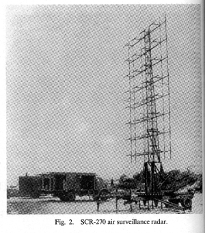
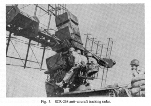
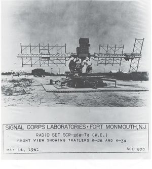
In the U.S., time was not quite as pressing, and development of VHF equipment was carried out. By the time of US entry into the war, the 105-MHz SCR-270 and the 205-MHz SCR-268 were available for use.
The success of the SCR-270 in detecting the aircraft approaching Pearl Harbor, and the failure of the associated command and control system, are part of the history of that era. The Australian RAAF deployed an SCR-270 at Dripstone cliff in Darwin in 1942.
Economy was enhanced by thinning of the array, removing the top and bottom rows from the main (azimuth) antenna, while retaining the entire column of six elements in the elevation array. The array itself was highly redundant, so that damage to a single element would not disable the radar. Processing and tracking, carried out by operators viewing cathode-ray tubes and manually controlling the antenna pedestal, were also redundant. What was lacking was the electronic beam steering used today for search and automatic tracking. Also lacking was the high resolution of modern arrays, which provide milliradian or better accuracy for fire control and missile guidance. The SCR-268 had to rely on accompanying optical trackers to refine its angle data for AA fire control, with the aid of searchlights slaved to the radar beam for night operations.
During World War II
Most of the air (and naval) actions in World War II fought with radar at UHF and below. Early U.S. radar equipment operated at 200 MHz. The XAF and CXAM search radars were designed by the Naval Research Laboratory, and were the first operational radars in the US fleet, produced by RCA. These were followed by large scale production of other 200-MHz systems, the SA, SK and SR. Other systems at 400, 600, and 1200 MHz became available by the end of the war.
Microwave radar made its appearance in 1943, after the magnetron was developed into a high-power, producible device. Low-power klystrons had long been used as local oscillators for superheterodyne receivers, as had parabolic reflector antennas. It required only a year to make the transition from the laboratory magnetron (mid-1940, in England) to the first 10-cm experimental tracker at the MIT Radiation Laboratory. Another year brought the field test model of the XT-1, and by mid-1943 the SCR-584 was being delivered from production. This radar had a beamwidth of 4 deg (70 mr), and could track aircraft with an accuracy of about 1.5 rnr, adequate for direct input to AA gun directors. Optical tracking continued to supplement the radar data, but the quality of automatic, servocontrolled tracking was such that radar-controlled guns were highly lethal within their design range. With the deployment of shells containing radar proximity fuzes, air defense reached a new high in effectiveness.
Early microwave search radars used parabolic-cylinder antennas, fed by slotted waveguides. An interesting variant of this design, used for rapid sector-scanning antennas in ground-controlled approach radar, was the Eagle scanner. It was known that the direction of radiation from a slotted waveguide would change when the transmitting wavelength was varied relative to the waveguide dimensions. Since rapid-tuning magnetrons were not available, the solution was to vary the waveguide dimension, using a mechanical linkage which periodically squeezed the sidewall. This changed the phase velocity within the guide, rephasing the radiation from successive slots to scan the beam through 10 or 20 degrees in angle.
Originally developed for airborne radar use, the Eagle scanner was applied to GCA radar in 1944, and it remains in that role today, competing successfully with electronically steered array antennas of much greater capability but higher cost.
By the end of the war, most U.S. search radar designs were using the doubly curved parabolic dish, in which shaped elevation coverage could be obtained either with an extended feed, or with a single horn feed and a distorted parabolic shape to the reflector. In Europe, the microwave dish antenna was widely used, but it did not completely replace the parabolic cylinder for search radar use. One of the most advanced of today's radars seems to have been inspired by the AN/CPS-I, using back-to-back cylindrical reflectors with line feeds. A major innovation, however, is the use of broad-band (equal line length) corporate feeds to achieve very low sidelobes and beam positions which remain invariant with frequency over the entire operating band of the system.
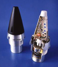
Proximity Fuze
A remarkable use of radar during World War II was the proximity fuze. The idea was simple, but seemingly impossible: put a tiny radar set on each artillery shell, and have the radar set trigger the detonation of the shell when it was close to its target. Smaller and more rugged tubes and appropriate control systems were developed, and the proximity fuze moved rapidly from experimental device to use in practical weapons. By the end of the war some 22 million had been produced, and they became very important in artillery, particularly anti-aircraft artillery. Proximity fuses, remain in use today.
One of the most important radar advances of the war was the movement to higher frequency (thus shorter) radio waves especially into the region of the electromagnetic spectrum called microwave. The shorter wavelengths were easier to focus into narrow beams. This meant that a distant object would reflect more energy back. Even more importantly, higher frequencies gave greater resolution. Directing anti-aircraft and long-range naval guns entirely by radar required microwave frequencies, as did displaying the topography below an aircraft when radar was used for navigation. The most important technical breakthrough in the move to higher frequency radar was the invention of the cavity magnetron. It was invented in 1940 by two British researchers, J.T. Randall and Henry Boot, at the University of Birmingham.
Museums
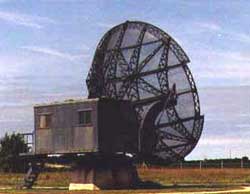
One of the most fascinating and technically complete radar and countermeasures (EW) museums is located at 1745 West Nursery Road, Linthicum, MD, USA. The National Electronics Museum houses both air, sea and ground based systems, including some of the last known radar components and antennas known to exist, including some prototype systems that had never been deployed. Features on display include a “Würzburg” antenna and a complete SCR-270 array.
