Milestone-Proposal:LORAN: Difference between revisions
From ETHW
(Article updated via HTTP request) |
(Article updated via HTTP request) |
||
| Line 3: | Line 3: | ||
Loran consist of three components: 1. a chain of radio transmitters creating an electronic lattice or grid upon the surface of the earth. 2. a loran receiver-indicator, something like an electronic timer with a cathode ray tube and 3. loran nautical and aeronautical charts or tables published, for example, by the US Navy Hydrographic Office. | Loran consist of three components: 1. a chain of radio transmitters creating an electronic lattice or grid upon the surface of the earth. 2. a loran receiver-indicator, something like an electronic timer with a cathode ray tube and 3. loran nautical and aeronautical charts or tables published, for example, by the US Navy Hydrographic Office. | ||
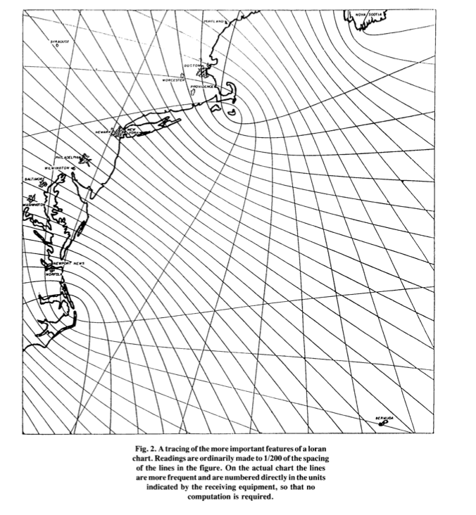
A simple explanation of how a navigator used loran in the 1940s to determine his position or fix follows next: first the line of position was established by measuring the relative time of arrival of two pulses which were known to have left two separate transmitters at times differing by a known interval. The time difference was noted in microseconds. With this information, charts and compasses, the navigator could plot a series of points on a chart plotting a line of position. But hold on; no fix point yet. A loran network with only two stations cannot provide meaningful navigation information as the 2-dimensional position of the receiver cannot be fixed without additional information to find the fix position. He may use a second pair of loran stations to determine a new line of position. Crossing of these two lines of position is the loran fix. For those wanting more details on hyperbolic system of navigation, see Chapter X111 of Bowditch's American Practical Navigator. | A simple explanation of how a navigator used loran in the 1940s to determine his position or fix follows next: first the line of position was established by measuring the relative time of arrival of two pulses which were known to have left two separate transmitters at times differing by a known interval. The time difference was noted in microseconds. With this information, charts and compasses, the navigator could plot a series of points on a chart plotting a line of position. But hold on; no fix point yet. A loran network with only two stations cannot provide meaningful navigation information as the 2-dimensional position of the receiver cannot be fixed without additional information to find the fix position. He may use a second pair of loran stations to determine a new line of position. Crossing of these two lines of position is the loran fix. For those wanting more details on hyperbolic system of navigation, see Chapter X111 of Bowditch's American Practical Navigator. | ||
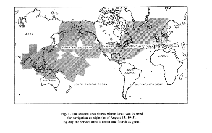
Today's loran operates on one of several frequencies between1700 and 2000 kHz. It enjoys propagation characteristics determined primarily by soil conductivity and ionospheric conditions. Both ground wave and sky waves can be used to provide coverage over an extensive area with few stations. Usually. stations of a pairs are located 200 to 400 miles or more. At one time, several station pairs were separated by 1000 to 1400 miles apart. Transmitters now in use radiate about 100kw and give a ground-wave range oversea water of about 700 nautical miles in the daytime. The day time range over land is seldom more than 250 miles even for high-flying aircraft and is scarcely 100miles at the surface of the earth. At night the ground-wave range oversea water is reduced to about 500 miles by the increase in atmospheric noise, but sky waves, which are almost completely absorbed by day,become effective and increase the reliable night range to about 1400miles. Generally | Today's loran operates on one of several frequencies between1700 and 2000 kHz. It enjoys propagation characteristics determined primarily by soil conductivity and ionospheric conditions. Both ground wave and sky waves can be used to provide coverage over an extensive area with few stations. Usually. stations of a pairs are located 200 to 400 miles or more. At one time, several station pairs were separated by 1000 to 1400 miles apart. Transmitters now in use radiate about 100kw and give a ground-wave range oversea water of about 700 nautical miles in the daytime. The day time range over land is seldom more than 250 miles even for high-flying aircraft and is scarcely 100miles at the surface of the earth. At night the ground-wave range oversea water is reduced to about 500 miles by the increase in atmospheric noise, but sky waves, which are almost completely absorbed by day,become effective and increase the reliable night range to about 1400miles. Generally, a number of stations are located so as to form a chain, with all but the end station in the group being double pulsing. In most parts of the world, signals can be received from at least two pairs of stations making it possible for a mariner to determine a fix using loran alone. | ||
A BRIEF HISTORY | A BRIEF HISTORY | ||
The name loran is derived from long-range navigation, a name given by Lawrence M. Harding, a career officer of the United States Coast Guard (USGC). Harding is one of the loran pioneers we should not forget. Beginning in 1943, USCG played a key role in | The name loran is derived from long-range navigation, a name given by Lawrence M. Harding, a career officer of the United States Coast Guard (USGC). Harding is one of the loran pioneers we should not forget. Beginning in 1943, USCG played a key role in getting some twenty-five loran transmitter stations up and running in the Aleutian Islands and the Pacific. Pierce gives credit to the USCG for loran stations in Iwo Jima and Okinawa, erected "upon the heels of the invading forces". Other loran stations in the Pacific guided the air force in its bombing campaign. Until quite recently, USGC crews have been manning loran stations in this part of the world for over 60 years. The United States loran system was replaced by GPS and shut-down on 8 February 2010. The nominator witnessed this great event, perhaps planting the seed for this milestone nomination. | ||
Other individuals should be mentioned: | |||
1941 - Melville Eastman of the Microwave Committee: First leader of a small group organized under the newly formed Radiation Laboratory of the Massachusetts Institute of Technology. This group was responsible for developing a new radio navigation system. CEO and founder of General Radio Corporation of Cambridge, Eastman had taken a leave of absence from his company during 1941 to 1943. | |||
Jack Pierce, a senior research fellow at Harvard University, Cambridge, MA joined the team in 1941. He would later receive the Medal For Engineering Excellence in 1990 for the design , teaching and advocacy of radio propagation, navigation and timing which led to the development of Loran, Loran C and Omega. Pierce, Eastman and a small group of radio experts soon began testing the United States' first hyperbolic radio aid to navigation, investigating radio frequencies, wave patters, reflection, and so on. | |||
Rad Lab was able to step after loran was running on a firm fundation. | Rad Lab was able to step after loran was running on a firm fundation. | ||
Rad Lab's project involvement terminated when loran was on a solid foundation.. | Rad Lab's project involvement terminated when loran was on a solid foundation.. | ||
Jack Pierce's epic article published by the IEEE in 1946 is the prime source for the information here. | Jack Pierce's epic article published by the IEEE in 1946 is the prime source for the information here. | ||
Among his many awards are a 1948 Presidential Certificate of Merit and the 1953 Morris Liebmann Prize of the Institute of Radio Engineers. | Among his many awards are a 1948 Presidential Certificate of Merit and the 1953 Morris Liebmann Prize of the Institute of Radio Engineers. | ||
JA Pierce was . . .???///// | JA Pierce was . . .???///// | ||
Revision as of 21:15, 10 December 2010
This Proposal has not been submitted and may only be edited by the original author.
Pierce Loran.pdf
Loran1.jpg .png
Loran_chart.png
This is a test