First-Hand:Development of the Instrument Landing System Glide Path: Difference between revisions
No edit summary |
No edit summary |
||
| Line 44: | Line 44: | ||
It is now over 66 years of operation since the system was accepted by the military, standardized by ICAO and in civilian use worldwide | It is now over 66 years of operation since the system was accepted by the military, standardized by ICAO and in civilian use worldwide | ||
[[Category:Transportation|{{PAGENAME}}]] | |||
[[Category:Navigation|{{PAGENAME}}]] | |||
Revision as of 14:54, 11 December 2012
Development of the Instrument Landing System Glide Path
Submitted by Leon Himmel, IEEE Life Fellow
The Instrument Landing System had been invented in the 1930s by Ernst Kramar IEEE Pioneer 1964 at Standard Electric Lorenz an ITT subsidiary. Andrew Alford IEEE Pioneer 1965, under a CAA contract, developed and tested a full system embodying a Localizer and a constant intensity Glide Path. Unfortunately the hyperbolic path was difficult to fly requiring constant attention of the pilot as the rate of descent varied from a steep start to a smooth touchdown. ITT then received a CAA/Signal Corps contract to develop an equi-signal Glide Path having a constant rate of descent.
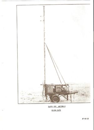
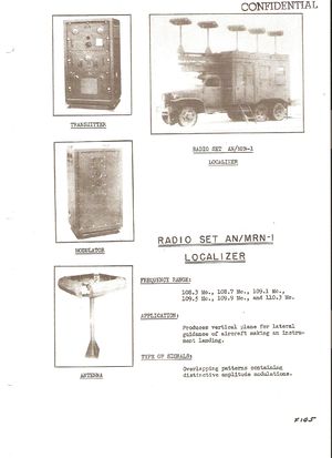
I joined ITT Federal Laboratories in January 1942 reporting to Andrew Alford. My assignment was the design of the antennas At that time the 330 megacycle frequency used was state of the art. The transmitter was designed by M. Charchian of ITTFL. The receivers were contracted to Western Electric. By May the Glide Path equipment was ready for installation and test at the CAA experimental facility at the Indianapolis airport. I was half of a two-man team under Chester Watts.
Designing the pair of antenna patterns to enable the lower end of the path as seen from the transmitter to vary from the path angle to zero at touchdown satisfied the firm requirement that the equipment be installed 400 feet from the runway for safety purposes. (U.S. Patent Watts, Himmel 2436843). The final design of the antenna system was accomplished by Morton Fuchs and myself.(U.S. Patent Himmel, Fuchs 2419552).
While it met the specification it made the system more susceptible to reflection interference at the lower end. The British system designed by ITT's Standard Telephone and Cable avoided the problem by using a frangible installation at the runway edge.
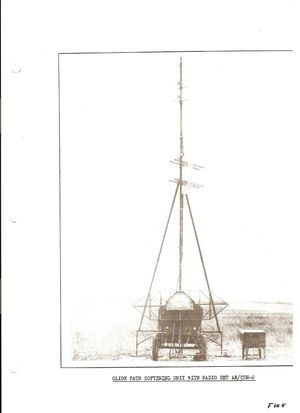
The CAA test pilot Pete Genero, assigned to the project, was a critical asset to the development of the system. I flew with him almost daily as he perfected the pilot’s landing approach method. His comment that the system, approaching touchdown, was “too sharp and needed to be softened” prompted me to devise a percent modulation control by adding carrier via a “softening” antenna (U.S. Patent Himmel 2419551) mounted half way up the antenna mast. By adjusting the carrier strength of the directive antenna the problem was solved.
On another occasion he called me to tell me “the path is too low” I told him it was off the air and that the antenna was on the ground. Never the less a quick demonstration convinced me that he was flying on noise. Upon landing I reversed the 90 and 150 cycle signals in the receiver and transmitter.
At the time of the first installation in a trailer flexible cable had not then been available. The standard transmission media was a ridged assembly of two conductors isolated by Isolantite beads enclosed in three quarter inch copper tubing. The cable problem handicapped a transportable system. A few months later, the CAA/Signal Corps notified us that in October we were to participate in a comparative test with an L band system designed by Sperry Rand and an X band system designed by MIT. At the same time there was concern that the ITT vertical antenna patterns dependence on a ground image might exclude installations in non- level sites.
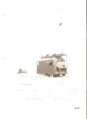
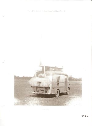
Cincinnati Airport located in a bowl like environment and Pittsburgh Airport located on a flattened mountaintop were the primary test sites. We reinstalled the entire equipment in a small truck for mobility and with newly developed flexible cable that gave us a new set of problems. The dielectric in the cable was extremely thermoplastic to the extent that made it useless. It was soon replaced by a new design and a new dielectric, consisting of a pair of coaxial cables that all but solved the problem. Unfortunately its electrical length was temperature sensitive to the extent we had to readjust the phase with temperature to keep the antennas properly fed. I proposed that all antenna cables be the same length and installed in the same environment. This was an immediate and low cost solution and was immediately adopted.
For ITT the test was a complete success notwithstanding the odd test environments. The equipment operated without a failure. In fact the equipment and the receiver reliabilities were outstanding throughout the entire period of development and test, not a single failure.
Both the Sperry and MIT systems were state of the art but unfortunately their receivers failed frequently during the tests. Further they did not meet the 400foot offset from the runway requirement although their narrow antenna beams made them less susceptible to site reflection problems.
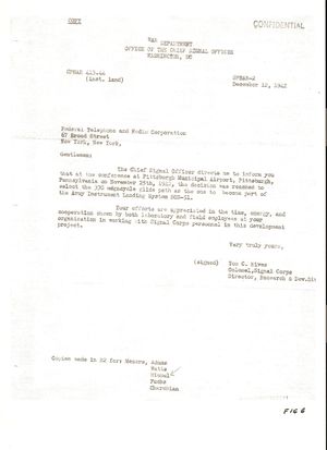
On December 12, 1942, the Office of the Chief Signal officer informed ITT that its 330 megacycle glide path had been selected as part of the Army Instrument Landing System SCS-51.
Andrew Alfred left ITT to form his own Consulting organization and was replaced by Paul Adams. Chester Watts left to join the Signal Corps. I remained as project engineer for the remainder of the development contract including writing the instruction and maintenance manuals and training Air Force pilot instructors in the use and piloting technique of the landing system.
ITT Telephone and Radio Manufacturing was awarded the production contract for the SCS-51 ILS the first unit of which was built and acceptance tested on a crash basis for use in the D-Day operation. The Air Force then installed the ITT ILS at airports in use throughout the globe.
PICAO at its meeting in Indianapolis in October 1946 designated the ITT ILS as the international standard for commercial landing systems. Although I had moved to assignments in electronic countermeasures I was called to participate if any questions arose. None did.
In the mid forties the FAA issued a fixed price invitation for glide path systems incorporating a requirement for constant impedance phasers. The requirement arose to simplify phase adjustments without affecting amplitude adjustments. Although I was no longer associated with the program the question intrigued me and I conceived a solution that solved the problem. (U.S. Patent Himmel 2420624) All other bidders took exception.to the requirement and were all disqualified. On a subsequent procurement the FAA required constant phase-signal amplitude adjusters Here again I conceived a solution. (U.S.Patent Himmel 2726369) All other bidders took exception to the requirement and were all disqualified.
It is now over 66 years of operation since the system was accepted by the military, standardized by ICAO and in civilian use worldwide
