|
|
| (25 intermediate revisions by 2 users not shown) |
| Line 3: |
Line 3: |
| Transformers at Pittsfield: A History of the General Electric Large Power Transformer Plant at Pittsfield, Massachusetts, by Thomas J. Blalock | | Transformers at Pittsfield: A History of the General Electric Large Power Transformer Plant at Pittsfield, Massachusetts, by Thomas J. Blalock |
|
| |
|
| In 1886, William Stanley first successfully demonstrated the use of the transformer in an alternating current system to provide electric lights for the Town of Great Barrington, Massachusetts.
| | [[Image:Blalock - book cover.jpg|thumb|center|400px]] |
|
| |
|
| In 1986, the General Electric Company announced that it would be closing its Large Power Transformer Operation in nearby Pittsfield. The existence of this plant was a direct result of Stanley's work one hundred years before. | | In 1886, [[William Stanley|William Stanley]] first successfully demonstrated the use of the [[Transformers|transformer]] in an alternating current system to provide electric lights for the Town of Great Barrington, Massachusetts. |
| | |
| | In 1986, the [[General Electric (GE)|General Electric Company]] announced that it would be closing its Large Power Transformer Operation in nearby Pittsfield. The existence of this plant was a direct result of Stanley's work one hundred years before. |
|
| |
|
| The technology associated with the design and manufacture of transformers in Pittsfield was sold to the Westinghouse Corporation, which built large transformers at a plant in Muncie, Indiana. However, about a year later, Westinghouse sold its Muncie operation to a foreign conglomerate known as "ABB" (ASEA - Brown-Boveri). Thus, one hundred years of transformer technology which had developed in the Berkshires of Western Massachusetts fell, unceremoniously, into foreign hands. | | The technology associated with the design and manufacture of transformers in Pittsfield was sold to the Westinghouse Corporation, which built large transformers at a plant in Muncie, Indiana. However, about a year later, Westinghouse sold its Muncie operation to a foreign conglomerate known as "ABB" (ASEA - Brown-Boveri). Thus, one hundred years of transformer technology which had developed in the Berkshires of Western Massachusetts fell, unceremoniously, into foreign hands. |
| Line 23: |
Line 25: |
| The men who headed the Pittsfield Transformer Operation during its eighty years of existence as a part of General Electric were (their actual titles changed from time to time as the corporate organization changed): | | The men who headed the Pittsfield Transformer Operation during its eighty years of existence as a part of General Electric were (their actual titles changed from time to time as the corporate organization changed): |
|
| |
|
| *Cummings C. Chesney | | *[[Cummings C. Chesney|Cummings C. Chesney]] |
| *Edward Wagner | | *Edward Wagner |
| *Louis Underwood | | *Louis Underwood |
| Line 52: |
Line 54: |
| Janice Calderwood provided information and material related to the Distribution Transformer Operation. Ed Kopf contributed valuable information on the early years of the Apprentice Program, as well as on many other aspects of life in the Pittsfield plant. William Coles provided details of Power House modifications over the years. Sam Sass contributed historical details related to the Stanley Library and other matters. R. Kelly Niederjohn and Stan Wilk provided information on the aspects of shipping huge transformers. | | Janice Calderwood provided information and material related to the Distribution Transformer Operation. Ed Kopf contributed valuable information on the early years of the Apprentice Program, as well as on many other aspects of life in the Pittsfield plant. William Coles provided details of Power House modifications over the years. Sam Sass contributed historical details related to the Stanley Library and other matters. R. Kelly Niederjohn and Stan Wilk provided information on the aspects of shipping huge transformers. |
|
| |
|
| John Anderson contributed information regarding the Empire State Building lightning study, as well as the operation of the High Voltage Laboratory and Projects EHV and UHV. John Benedict contributed photos and other material related to the Building 9 High Voltage Labora- tory. Details relative to lightning arrester development and the operation of the Dufour cold-cathode oscillograph were provided by Tom Carpenter. Finally, much information about the operation of the transformer testing facility was contributed by G.G. ("Pete") Kemp and by Tom Stanfield. | | John Anderson contributed information regarding the Empire State Building lightning study, as well as the operation of the High Voltage Laboratory and Projects EHV and UHV. John Benedict contributed photos and other material related to the Building 9 High Voltage Laboratory. Details relative to lightning arrester development and the operation of the Dufour cold-cathode oscillograph were provided by Tom Carpenter. Finally, much information about the operation of the transformer testing facility was contributed by G.G. ("Pete") Kemp and by Tom Stanfield. |
|
| |
|
| Access to archival material stored in the Pittsfield G.E. plant was provided by Tom Bednarz, William Carter, Jr., and Art Stringer. | | Access to archival material stored in the Pittsfield G.E. plant was provided by Tom Bednarz, William Carter, Jr., and Art Stringer. |
| Line 70: |
Line 72: |
| == Chapter 1: The Early Years == | | == Chapter 1: The Early Years == |
|
| |
|
| "One day Mr. Whittlesey came to Barrington and I told him of my withdrawal from the Pittsburgh company. He asked me to come to Pittsfield and see some of his friends before I embarked anew. I came up to Pittsfield and met two sterling men, the late W.R. Plunkett and the late W.W. Gamwell. Mr. Plunkett called a meeting of businessmen at his residence on East Street. A dozen or so attended this meeting and we discussed the starting of a company to build transformers. Mr. Whittlesey then got subscriptions for $25,000. Two companies were organized. One, 'The Laboratory Company', with a small capital, in which Messrs. Chesney, Kelly and myself were the principle stockholders, and the other, 'The Manufacturing Company'. Mr. Chesney was chosen as the works manager of the manufacturing company and we started in." | | "One day Mr. Whittlesey came to Barrington and I told him of my withdrawal from the Pittsburgh company. He asked me to come to Pittsfield and see some of his friends before I embarked anew. I came up to Pittsfield and met two sterling men, the late W.R. Plunkett and the late W.W. Gamwell. Mr. Plunkett called a meeting of businessmen at his residence on East Street. A dozen or so attended this meeting and we discussed the starting of a company to build transformers. Mr. Whittlesey then got subscriptions for $25,000. Two companies were organized. One, 'The Laboratory Company', with a small capital, in which Messrs. [[Cummings C. Chesney|Chesney]], Kelly and myself were the principle stockholders, and the other, 'The Manufacturing Company'. Mr. Chesney was chosen as the works manager of the manufacturing company and we started in." |
|
| |
|
| William Stanley | | - [[William Stanley|William Stanley]] |
|
| |
|
| The above quotation describes William Stanley's departure from the Westinghouse Company in Pittsburgh, and the subsequent establishment of a transformer manufacturing plant in Pittsfield. Thus began the ninety-six year history of the manufacture of transformers in Pittsfield which ended with the closing of the Large Transformer Operation of General Electric in 1987. | | The above quotation describes [[William Stanley|William Stanley]]'s departure from the Westinghouse Company in Pittsburgh, and the subsequent establishment of a transformer manufacturing plant in Pittsfield. Thus began the ninety-six year history of the manufacture of transformers in Pittsfield which ended with the closing of the Large Transformer Operation of General Electric in 1987. |
|
| |
|
| The Stanley Laboratory Company originated in a building on Cottage Row (now Eagle Street) in Pittsfield, in 1890. The Stanley Electric Manufacturing Company went into operation on Clapp Avenue (now gone) in January of 1891. The Works Engineer was Cummings Chesney and the Shop Superintendent was John Kelman. The first shipment of "S.K.C." (Stanley-Kelly-Chesney) transformers left the shop on April 1, 1891. | | The Stanley Laboratory Company originated in a building on Cottage Row (now Eagle Street) in Pittsfield, in 1890. The Stanley Electric Manufacturing Company went into operation on Clapp Avenue (now gone) in January of 1891. The Works Engineer was Cummings Chesney and the Shop Superintendent was John Kelman. The first shipment of "S.K.C." (Stanley-Kelly-Chesney) transformers left the shop on April 1, 1891. |
| Line 104: |
Line 106: |
| The identified buildings served the following functions in 1908: | | The identified buildings served the following functions in 1908: |
|
| |
|
| <u>Buildings 1-2-3</u>
| | === Buildings 1-2-3 === |
|
| |
|
| These were the main transformer assembly and testing bays. Building 1 was constructed in 1900, and Buildings 2 and 3 were added around the time that the plant became a part of G.E. These buildings still exist today. | | These were the main transformer assembly and testing bays. Building 1 was constructed in 1900, and Buildings 2 and 3 were added around the time that the plant became a part of G.E. These buildings still exist today. |
|
| |
|
| <u>Building 4</u>
| | === Building 4 === |
|
| |
|
| This was the main winding area for the larger sizes of transformers. It also still exists. This was also the assembly area for small types of transformers. | | This was the main winding area for the larger sizes of transformers. It also still exists. This was also the assembly area for small types of transformers. |
|
| |
|
| <u>Building 5.</u>
| | === Building 5 === |
|
| |
|
| This was the main shipping area. It was served by a railroad siding running along its south side; this siding also ran through the south end of the Building 1-2-3 complex. This building eventually housed offices and the "copper shop", and still exists. | | This was the main shipping area. It was served by a railroad siding running along its south side; this siding also ran through the south end of the Building 1-2-3 complex. This building eventually housed offices and the "copper shop", and still exists. |
|
| |
|
| <u>Building 6</u>
| | === Building 6 === |
|
| |
|
| This was the area in which the various types of insulation (such as pressboard, etc.) needed in the transformers was prepared. It still exists. | | This was the area in which the various types of insulation (such as pressboard, etc.) needed in the transformers was prepared. It still exists. |
|
| |
|
| <u>Building 7</u>
| | === Building 7 === |
|
| |
|
| This was where the thin laminations of steel needed to build up the magnetic cores of the transformers were fabricated. This building served several other functions in later years. It still stands, but is somewhat derelict. | | This was where the thin laminations of steel needed to build up the magnetic cores of the transformers were fabricated. This building served several other functions in later years. It still stands, but is somewhat derelict. |
|
| |
|
| <u>Building 8</u>
| | === Building 8 === |
|
| |
|
| This was the Laboratory building where the development of transformer insulation materials, and the high voltage testing of same, was carried on. It still stands, but is also somewhat derelict. | | This was the Laboratory building where the development of transformer insulation materials, and the high voltage testing of same, was carried on. It still stands, but is also somewhat derelict. |
|
| |
|
| <u>Building 9</u>
| | === Building 9 === |
|
| |
|
| This no longer exists; it was a storage facility for the oils used in transformers for insulation and cooling. | | This no longer exists; it was a storage facility for the oils used in transformers for insulation and cooling. |
|
| |
|
| <u>Building 10</u>
| | === Building 10 === |
|
| |
|
| This was identified as a Carpenter and Pattern Shop, and no Longer exists. | | This was identified as a Carpenter and Pattern Shop, and no Longer exists. |
|
| |
|
| <u>Building 11</u>
| | === Building 11 === |
|
| |
|
| This was the Brass Foundry and Tank Shop, for the production of brass electrical fittings and the fabrication of the iron tanks which held the working parts of the transformers. The site is presently occupied by a new Building 11 dating from the 1960's. | | This was the Brass Foundry and Tank Shop, for the production of brass electrical fittings and the fabrication of the iron tanks which held the working parts of the transformers. The site is presently occupied by a new Building 11 dating from the 1960's. |
| Line 178: |
Line 180: |
| An interesting aspect of the electric power system in the Morningside plant is that it was not the standard three-phase type of power which is universally used now. The generation and distribution was via a system known as "two-phase". | | An interesting aspect of the electric power system in the Morningside plant is that it was not the standard three-phase type of power which is universally used now. The generation and distribution was via a system known as "two-phase". |
|
| |
|
| William Stanley designed and built a great deal of two-phase equipment during the 1890's, partly because of a belief in its superiority over three-phase, but also to avoid patent infringement problems with General Electric and Westinghouse who both used the three-phase system. | | [[William Stanley|William Stanley]] designed and built a great deal of two-phase equipment during the 1890's, partly because of a belief in its superiority over three-phase, but also to avoid patent infringement problems with [[General Electric (GE)|General Electric]] and Westinghouse who both used the three-phase system. |
|
| |
|
| In fact, three-phase is decidedly superior for power distribution purposes. Thus, the old two-phase systems have gradually faded out of existence. However, two-phase power was so firmly entrenched in the Pittsfield plant that remnants of it still exist today! This has to do with the existence of old two-phase motors which have never been replaced. | | In fact, three-phase is decidedly superior for power distribution purposes. Thus, the old two-phase systems have gradually faded out of existence. However, two-phase power was so firmly entrenched in the Pittsfield plant that remnants of it still exist today! This has to do with the existence of old two-phase motors which have never been replaced. |
| Line 279: |
Line 281: |
| *An addition (known as "17Ext") was made to <u>Building 17</u>, located near the corner of Tyler Street and Woodlawn Avenue. Originally built in 1910, Building 17 had become the Tank Shop where steel transformer tanks were fabricated. The original Tank Shop had been on the site of the present Building 11. | | *An addition (known as "17Ext") was made to <u>Building 17</u>, located near the corner of Tyler Street and Woodlawn Avenue. Originally built in 1910, Building 17 had become the Tank Shop where steel transformer tanks were fabricated. The original Tank Shop had been on the site of the present Building 11. |
|
| |
|
| *<u>William Stanley</u> died in Great Barrington. | | *[[William Stanley|William Stanley]] died in Great Barrington. |
|
| |
|
| *G.E. sponsored an elaborate production of Gilbert and Sullivan's "The Mikado", at the <u>Colonial Theatre</u> on South Street in Pittsfield. | | *G.E. sponsored an elaborate production of Gilbert and Sullivan's "The Mikado", at the <u>Colonial Theatre</u> on South Street in Pittsfield. |
| Line 389: |
Line 391: |
| 1927: | | 1927: |
|
| |
|
| *<u>Capacitors</u> were being manufactured in a part of Building 42. | | *[[Capacitors|Capacitors]] were being manufactured in a part of Building 42. |
|
| |
|
| *The <u>Works Restaurant</u> was now operating in a section of Building 43, known as "43B". A cafeteria for the "South Side" was operating in Building 27. | | *The <u>Works Restaurant</u> was now operating in a section of Building 43, known as "43B". A cafeteria for the "South Side" was operating in Building 27. |
| Line 403: |
Line 405: |
| Apprentices attended one two-hour class each working day. During the first year of the program, they learned how to operate every one of the machines in the shop. Then, they were sent to areas related to their particular line of interest: drafting, tool-making, pattern-making, maintenance, or engineering. There were both three and four year courses, and an entrance exam was mandatory. | | Apprentices attended one two-hour class each working day. During the first year of the program, they learned how to operate every one of the machines in the shop. Then, they were sent to areas related to their particular line of interest: drafting, tool-making, pattern-making, maintenance, or engineering. There were both three and four year courses, and an entrance exam was mandatory. |
|
| |
|
| [[Image:Blalock - page 23 (bot).jpg|thumb|center|650px|Works Manager Cummings C. Chesney, along with Guiseppe Faccioli (in wheelchair) and W.S. Moody, inspect the largest single-phase transformer built as of 1926 (water-cooled, 60-cycles, 28,886-Kva, 100 tons for the Wallenpaupack Substation of the Pennsylvania Power and Light system; the three-phase bank of which it was to be a part was rated for 220-Kv to 66-Kv with an 11-Kv tertiary winding), G.E. Current News, January, 1926]] | | [[Image:Blalock - page 28.jpg|thumb|center|650px|Works Manager Cummings C. Chesney, along with Guiseppe Faccioli (in wheelchair) and W.S. Moody, inspect the largest single-phase transformer built as of 1926 (water-cooled, 60-cycles, 28,886-Kva, 100 tons for the Wallenpaupack Substation of the Pennsylvania Power and Light system; the three-phase bank of which it was to be a part was rated for 220-Kv to 66-Kv with an 11-Kv tertiary winding), G.E. Current News, January, 1926]] |
|
| |
|
| Apprentices were able to obtain experience working in any of the different departments in the plant: principally Power Transformer, Distribution Transformer, Regulators, Load Ratio Control, Foundry, Tool Room, Lightning Arresters, and Bushings. | | Apprentices were able to obtain experience working in any of the different departments in the plant: principally Power Transformer, Distribution Transformer, Regulators, Load Ratio Control, Foundry, Tool Room, Lightning Arresters, and Bushings. |
| Line 415: |
Line 417: |
| Other recollections of Mr. Kopf's include the fact that two small steam locomotives were used to haul materials around the plant in those days. Tracks ran up the hill from South Gate (at East Street), over the railroad, and out North Gate onto Woodlawn Avenue; then back into the plant at Building 17 and on to the Tank Shop (Building 14). In the winter, when ice and snow were on the tracks coming up from South Gate, men had to run ahead of the locomotive with buckets of sand to throw on the tracks for traction! Sometimes, with big loads, both locomotives had to be used running in tandem. | | Other recollections of Mr. Kopf's include the fact that two small steam locomotives were used to haul materials around the plant in those days. Tracks ran up the hill from South Gate (at East Street), over the railroad, and out North Gate onto Woodlawn Avenue; then back into the plant at Building 17 and on to the Tank Shop (Building 14). In the winter, when ice and snow were on the tracks coming up from South Gate, men had to run ahead of the locomotive with buckets of sand to throw on the tracks for traction! Sometimes, with big loads, both locomotives had to be used running in tandem. |
|
| |
|
| Also, during that era, the twelve to fifteen thousand employees in the Pittsfield plant received their pay in cash (no checks). Money was picked up at the First Agricultural Bank in Pittsfield and brought to the plant in a large safe mounted on a flatbed truck. This was a battery-operated truck, and only enough charge was put into the batteries to make the trip to the bank and back again! Armed guards | | Also, during that era, the twelve to fifteen thousand employees in the Pittsfield plant received their pay in cash (no checks). Money was picked up at the First Agricultural Bank in Pittsfield and brought to the plant in a large safe mounted on a flatbed truck. This was a battery-operated truck, and only enough charge was put into the batteries to make the trip to the bank and back again! Armed guards from the plant accompanied the truck, and additional armed guards from the bank were on hand for the loading of the money into the truck. |
| | |
| from the plant accompanied the truck, and additional armed guards from the bank were on hand for the loading of the money into the truck. | |
|
| |
|
| The truck was driven into a freight elevator in Building 42 and taken up to the Payroll Department. Each department in the plant had a fold-up wire cage which was set up at a designated spot on pay day. The money was distributed to these various locations by other trucks. At each stop, the money and a payroll clerk were left in the cage. Pay envelopes were arranged by clock number, and it took only ten or fifteen minutes in each department to distribute all of the pay. | | The truck was driven into a freight elevator in Building 42 and taken up to the Payroll Department. Each department in the plant had a fold-up wire cage which was set up at a designated spot on pay day. The money was distributed to these various locations by other trucks. At each stop, the money and a payroll clerk were left in the cage. Pay envelopes were arranged by clock number, and it took only ten or fifteen minutes in each department to distribute all of the pay. |
| Line 451: |
Line 451: |
| *The first commercial <u>Impulse Test</u> was performed on a transformer. This test simulates the effect of lightning-related surges which the transformer may be subjected to in service and demonstrates that the transformer insulation will withstand such mistreatment. | | *The first commercial <u>Impulse Test</u> was performed on a transformer. This test simulates the effect of lightning-related surges which the transformer may be subjected to in service and demonstrates that the transformer insulation will withstand such mistreatment. |
|
| |
|
| *<u>Giuseppe Faccioli</u> retires due to ill health. | | *[[Archives:Papers of G. Faccioli|Giuseppe Faccioli]] retires due to ill health. |
|
| |
|
| *<u>Cummings C. Chesney</u> retires. | | *[[Cummings C. Chesney|Cummings C. Chesney]] retires. |
|
| |
|
| *<u>Building 62</u> is built south of East Street. This functioned as the Gas Plant, producing various types of bottled gas for use in production processes. | | *<u>Building 62</u> is built south of East Street. This functioned as the Gas Plant, producing various types of bottled gas for use in production processes. |
| Line 485: |
Line 485: |
| Guglielmo Camilli was a native of Rome, Italy; he received his engineering degree from the Royal Polytechnic School of Turin in 1922. In 1926, he began his career with General Electric as a Development Engineer in Pittsfield. | | Guglielmo Camilli was a native of Rome, Italy; he received his engineering degree from the Royal Polytechnic School of Turin in 1922. In 1926, he began his career with General Electric as a Development Engineer in Pittsfield. |
|
| |
|
| In 1956, he was named Supervisor of Power Transformer Advance Product Engineering. By 1958, he had received a total of fifty-five patents, more than anyone else in the General Electric Company at the time. He was twice the recipient of the Coffin Award, the highest employee honor bestowed by General Electric. He was the author of a book on the subject of transformer engineering, and authored many technical papers throughout his career. | | In 1956, he was named Supervisor of Power Transformer Advance Product Engineering. By 1958, he had received a total of fifty-five patents, more than anyone else in the [[General Electric (GE)|General Electric Company]] at the time. He was twice the recipient of the Coffin Award, the highest employee honor bestowed by General Electric. He was the author of a book on the subject of transformer engineering, and authored many technical papers throughout his career. |
|
| |
|
| Camilli was an avid amateur astronomer. He ground his own lenses and built his own telescopes. He was a member of the volunteer Pittsfield G.E. Speakers Bureau; as such, he presented a very popular talk around the country which was called "A Trip through the Universe". He predicted that the United States would reach the moon by 1967 (not far off!). He also used his immense knowledge of transformer insulation structures and cooling methods to design a "transformer for use on the moon" in 1955! He operated his own personal observatory at his home on East New Lenox Road in Pittsfield. | | Camilli was an avid amateur astronomer. He ground his own lenses and built his own telescopes. He was a member of the volunteer Pittsfield G.E. Speakers Bureau; as such, he presented a very popular talk around the country which was called "A Trip through the Universe". He predicted that the United States would reach the moon by 1967 (not far off!). He also used his immense knowledge of transformer insulation structures and cooling methods to design a "transformer for use on the moon" in 1955! He operated his own personal observatory at his home on East New Lenox Road in Pittsfield. |
| Line 493: |
Line 493: |
| === Cummings C. Chesney === | | === Cummings C. Chesney === |
|
| |
|
| C.C. Chesney, a native of Pennsylvania, was born in 1863. Following his graduation from Pennsylvania State College in 1885, he taught mathematics and chemistry until becoming associated with William Stanley in 1888, in Great Barrington, Mass., as a chemist and engineer. | | [[Cummings C. Chesney|C.C. Chesney]], a native of Pennsylvania, was born in 1863. Following his graduation from Pennsylvania State College in 1885, he taught mathematics and chemistry until becoming associated with [[William Stanley|William Stanley]] in 1888, in Great Barrington, Mass., as a chemist and engineer. |
|
| |
|
| He followed Stanley to the United States Electric Lighting Company in Newark, New Jersey (a subsidiary of the Westinghouse Company) in 1889. He then became associated with the Stanley Electrical Manufacturing Company in Pittsfield as an electrical engineer in 1891. He was the "C" in the S.K.C. system marketed by Stanley. | | He followed Stanley to the United States Electric Lighting Company in Newark, New Jersey (a subsidiary of the Westinghouse Company) in 1889. He then became associated with the Stanley Electrical Manufacturing Company in Pittsfield as an electrical engineer in 1891. He was the "C" in the S.K.C. system marketed by Stanley. |
| Line 503: |
Line 503: |
| Chesney was very active in local business activities as well as civic affairs. He was active in the Boys' Club of Pittsfield, and was a member of the Chamber of Commerce there. | | Chesney was very active in local business activities as well as civic affairs. He was active in the Boys' Club of Pittsfield, and was a member of the Chamber of Commerce there. |
|
| |
|
| In 1921, he received the Edison Medal from the American Institute of Electrical Engineers, and he served as President of that organization from 1926 to 1927. The Edison Medal is the highest award given to an electrical engineer, and is for meritorious achievements in electrical science, engineering and art. | | In 1921, he received the [[IEEE Edison Medal|Edison Medal]] from the [[AIEE History 1884-1963|American Institute of Electrical Engineers]], and he served as [[Presidents of the American Institute of Electrical Engineers (AIEE)|President of that organization from 1926 to 1927]]. The Edison Medal is the highest award given to an electrical engineer, and is for meritorious achievements in electrical science, engineering and art. |
|
| |
|
| Cummings Chesney retired in 1930 and died in 1947. He was survived by his widow, Elizabeth, four daughters, a son, and eleven grandchildren. | | Cummings Chesney retired in 1930 and died in 1947. He was survived by his widow, Elizabeth, four daughters, a son, and eleven grandchildren. |
| Line 509: |
Line 509: |
| === Giuseppe Faccioli === | | === Giuseppe Faccioli === |
|
| |
|
| Giuseppe Faccioli was born in Rome, Italy in 1877 and graduated with high honors from the Institute of Technology in Milan in 1899 as a mechanical and electrical engineer. He came to the United States in 1902 and obtained a position with the New York Edison Company (the ancestor of Consolidated Edison in New York City). One year later, however, he transferred to the employ of the Interborough Rapid Transit Company, the builders of the first subway system (the IRT) in New York City. | | [[Archives:Papers of G. Faccioli|Giuseppe Faccioli]] was born in Rome, Italy in 1877 and graduated with high honors from the Institute of Technology in Milan in 1899 as a mechanical and electrical engineer. He came to the United States in 1902 and obtained a position with the New York Edison Company (the ancestor of Consolidated Edison in New York City). One year later, however, he transferred to the employ of the Interborough Rapid Transit Company, the builders of the first subway system (the IRT) in New York City. |
|
| |
|
| Then, in 1904, he went to work for the Crocker-Wheeler Company in Ampere, New Jersey (near East Orange). Crocker-Wheeler had been building rotating electrical machines for the Stanley Company and, as a result, he came into contact with William Stanley. This led to his joining Stanley in Great Barrington (by this time, the Stanley Company in Pittsfield was a subsidiary of General Electric, and Stanley himself had gone back to Great Barrington to engage in other ventures). | | Then, in 1904, he went to work for the Crocker-Wheeler Company in Ampere, New Jersey (near East Orange). Crocker-Wheeler had been building rotating electrical machines for the Stanley Company and, as a result, he came into contact with William Stanley. This led to his joining Stanley in Great Barrington (by this time, the Stanley Company in Pittsfield was a subsidiary of General Electric, and Stanley himself had gone back to Great Barrington to engage in other ventures). |
| Line 529: |
Line 529: |
| In 1922, he devised the 1,000,000 volt three-phase arc which remained a mainstay of public demonstrations for the next fifty years or so. | | In 1922, he devised the 1,000,000 volt three-phase arc which remained a mainstay of public demonstrations for the next fifty years or so. |
|
| |
|
| He was also involved in the development of equipment such as high current testing transformers, cable testing apparatus, x-ray transformers, high frequency transformers, power and filament transformers for vacuum tube rectifiers, and air-blast type power transformers for use by the Interborough Rapid Transit Company of New York City (builders of the first subway system there). | | He was also involved in the development of equipment such as high current testing transformers, cable testing apparatus, x-ray transformers, high frequency transformers, power and filament transformers for [[Electron (or Vacuum) Tubes|vacuum tube]] rectifiers, and air-blast type power transformers for use by the Interborough Rapid Transit Company of New York City (builders of the first subway system there). |
|
| |
|
| In later years, he was also intimately involved with the design of impulse generators for laboratory testing with simulated lightning surges. | | In later years, he was also intimately involved with the design of impulse generators for laboratory testing with simulated lightning surges. |
| Line 541: |
Line 541: |
| He received the appointment of Manager, Laboratory-Engineering Department in 1952, and, in 1953, was named as the Consultant of Professional Employee Relations for all technical employees in the Engineering Services Division of the General Electric Company. | | He received the appointment of Manager, Laboratory-Engineering Department in 1952, and, in 1953, was named as the Consultant of Professional Employee Relations for all technical employees in the Engineering Services Division of the General Electric Company. |
|
| |
|
| He originated and supervised the lightning investigation at the Empire State Building which yielded .a vast amount of valuable data on natural lightning. Also, under his direction, 10,000,000 volt discharges were produced by impulse generators at the 1939 New York World's Fair, and the new High Voltage Laboratory building (Building 9) was opened in Pittsfield in 1949. | | He originated and supervised the lightning investigation at the Empire State Building which yielded a vast amount of valuable data on natural lightning. Also, under his direction, 10,000,000 volt discharges were produced by impulse generators at the 1939 New York World's Fair, and the new High Voltage Laboratory building (Building 9) was opened in Pittsfield in 1949. |
|
| |
|
| Dr. McEachron was a recognized authority on lightning, world-wide. He was often called upon to testify in cases of lightning-caused injuries and damage. In 1940, he coauthored the book "Playing with Lightning", and, in 1948, he wrote the article "Lightning and Lightning Protection" for inclusion in the Encyclopedia Britannica. He was also the author of many technical papers on the subject of lightning and related topics. | | Dr. McEachron was a recognized authority on lightning, world-wide. He was often called upon to testify in cases of lightning-caused injuries and damage. In 1940, he coauthored the book "Playing with Lightning", and, in 1948, he wrote the article "Lightning and Lightning Protection" for inclusion in the Encyclopedia Britannica. He was also the author of many technical papers on the subject of lightning and related topics. |
| Line 629: |
Line 629: |
| *An unfortunate record was set by the occurrence of seventy-five <u>lost-time accidents</u> for the year. | | *An unfortunate record was set by the occurrence of seventy-five <u>lost-time accidents</u> for the year. |
|
| |
|
| <u>Pyranol</u>
| | === Pyranol === |
|
| |
|
| Also, in 1936, thirty Pyranol network transformers were built for the New York and Queens Electric Light and Power Company in New York City. | | Also, in 1936, thirty Pyranol network transformers were built for the New York and Queens Electric Light and Power Company in New York City. |
| Line 689: |
Line 689: |
| *The Capitol Theatre in Pittsfield was pre- viewing the new film <u>"Edison, The Man"</u>. | | *The Capitol Theatre in Pittsfield was pre- viewing the new film <u>"Edison, The Man"</u>. |
|
| |
|
| <u>World War II</u>
| | === World War II === |
|
| |
|
| In the interest of national security, nothing was published in the Pittsfield G.E. News regarding any involvement in technical activities related to the war effort, on the part of the Pittsfield G.E. plant. | | In the interest of national security, nothing was published in the Pittsfield G.E. News regarding any involvement in technical activities related to the war effort, on the part of the Pittsfield G.E. plant. |
|
| |
|
| However, Harry Mason, a former Design Engineer in the Pittsfield transformer operation, has some interesting recollections of this era. Most notably, he was involved in a special project which included the design and manufacture of a large quantity of special transformers for use in the Manhattan Project, which led to the development of the atomic bomb. | | However, Harry Mason, a former Design Engineer in the Pittsfield transformer operation, has some interesting recollections of this era. Most notably, he was involved in a special project which included the design and manufacture of a large quantity of special transformers for use in the [[Manhattan Project|Manhattan Project]], which led to the development of the atomic bomb. |
|
| |
|
| These were rectifier transformers which were shipped to Oak Ridge, Tennessee. They were used in conjunction with rectifiers to produce direct current needed to accelerate uranium ions through a strong magnetic field. This would then separate fissionable U235 from U238. | | These were rectifier transformers which were shipped to Oak Ridge, Tennessee. They were used in conjunction with rectifiers to produce direct current needed to accelerate uranium ions through a strong magnetic field. This would then separate fissionable U235 from U238. |
| Line 727: |
Line 727: |
| *The Pittsfield plant <u>guards were armed</u>! | | *The Pittsfield plant <u>guards were armed</u>! |
|
| |
|
| <u>The Story of the Silver Transformers</u>
| | === The Story of the Silver Transformers === |
|
| |
|
| In 1942, due to a critical shortage of copper, twelve transformers were built at the Pittsfield plant which had silver windings! | | In 1942, due to a critical shortage of copper, twelve transformers were built at the Pittsfield plant which had silver windings! |
| Line 781: |
Line 781: |
| *The <u>High Voltage Laboratory</u> (Building 9) is under construction. | | *The <u>High Voltage Laboratory</u> (Building 9) is under construction. |
|
| |
|
| *<u>Cummings C. Chesney</u> died. | | *[[Cummings C. Chesney|Cummings C. Chesney]] died. |
|
| |
|
| *The old <u>Power House</u> smokestack was torn down. | | *The old <u>Power House</u> smokestack was torn down. |
| Line 1,217: |
Line 1,217: |
| [[Image:Blalock - page 90 (bot).jpg|thumb|center|650px|A core and coils being tanked in Building 100 courtesy of General Electric Company]] | | [[Image:Blalock - page 90 (bot).jpg|thumb|center|650px|A core and coils being tanked in Building 100 courtesy of General Electric Company]] |
|
| |
|
| <u>Vacuum Treat</u>
| | === Vacuum Treat === |
|
| |
|
| Elaborate precautions were taken to insure that the paper insulation used in the transformer windings was as free of moisture as possible, so as to retain its maximum insulating capability. This was the function of the vacuum treat cycle. | | Elaborate precautions were taken to insure that the paper insulation used in the transformer windings was as free of moisture as possible, so as to retain its maximum insulating capability. This was the function of the vacuum treat cycle. |
| Line 1,425: |
Line 1,425: |
| 1973: | | 1973: |
|
| |
|
| *Les Jump, an engineer who re-located to Pittsfield from the AEI Company of Manchester. in England, warned of the very real possibility of a <u>plant closing</u> here because he had seen | | *Les Jump, an engineer who re-located to Pittsfield from the AEI Company of Manchester. in England, warned of the very real possibility of a <u>plant closing</u> here because he had seen it happen there! |
| | |
| it happen there! | |
|
| |
|
| *A <u>Family Day</u> was held in the plant in April. | | *A <u>Family Day</u> was held in the plant in April. |
| Line 1,437: |
Line 1,435: |
| *Competitor <u>Central Moloney</u> of St. Louis, Missouri went out of the power transformer business. | | *Competitor <u>Central Moloney</u> of St. Louis, Missouri went out of the power transformer business. |
|
| |
|
| *<u>ASEA</u> of Sweden won a large order from the Commonwealth Edison Company, of Chicago, beating out General Electric, Westinghouse, | | *<u>ASEA</u> of Sweden won a large order from the Commonwealth Edison Company, of Chicago, beating out General Electric, Westinghouse, and the McGraw-Edison Company. This was for seven single-phase generator step-up transformers. |
| | |
| and the McGraw-Edison Company. This was for seven single-phase generator step-up transformers. | |
|
| |
|
| *The New England Power Company's <u>Bear Swamp</u> pumped storage hydroelectric, generating facility on the Deerfield River (in the towns of Florida and Rowe, Mass.) was soon to go "on-line". This plant used two generator step-up transformers from Pittsfield with their two 300-Megawatt generators. | | *The New England Power Company's <u>Bear Swamp</u> pumped storage hydroelectric, generating facility on the Deerfield River (in the towns of Florida and Rowe, Mass.) was soon to go "on-line". This plant used two generator step-up transformers from Pittsfield with their two 300-Megawatt generators. |
| Line 1,465: |
Line 1,461: |
| 1975: | | 1975: |
|
| |
|
| *Three new <u>winding lathes</u>(vertical type) were installed in Building 1, plus two of | | *Three new <u>winding lathes</u>(vertical type) were installed in Building 1, plus two of the more conventional horizontal type. |
| | |
| the more conventional horizontal type. | |
|
| |
|
| *The G.E. Transformer Division's computers were all centralized in <u>Building 34</u> on East Street. | | *The G.E. Transformer Division's computers were all centralized in <u>Building 34</u> on East Street. |
| Line 1,539: |
Line 1,533: |
| 1981: | | 1981: |
|
| |
|
| *<u>Building 73,</u> a regulator life-test facility, | | *<u>Building 73,</u> a regulator life-test facility, was constructed off of New York Avenue. |
| | |
| was constructed off of New York Avenue. | |
|
| |
|
| *The <u>Silver Lake Barge</u> was dismantled. This had been a facility on Silver Lake, operated by G.E. Ordnance, for the purpose of torpedo sonic testing. | | *The <u>Silver Lake Barge</u> was dismantled. This had been a facility on Silver Lake, operated by G.E. Ordnance, for the purpose of torpedo sonic testing. |
| Line 1,603: |
Line 1,595: |
| 1986: | | 1986: |
|
| |
|
| *A <u>rumor</u> circulated that foreign competitor ASEA planned to take over the Pittsfield | | *A <u>rumor</u> circulated that foreign competitor ASEA planned to take over the Pittsfield operation. This proved to be untrue. |
| | |
| operation. This proved to be untrue. | |
|
| |
|
| *The announcement of the end of the transformer business in Pittsfield was made in the Berkshire Eagle on November 22. <u>One thousand jobs would be lost.</u> | | *The announcement of the end of the transformer business in Pittsfield was made in the Berkshire Eagle on November 22. <u>One thousand jobs would be lost.</u> |
| Line 1,647: |
Line 1,637: |
| [[Image:Blalock - page 126.jpg|thumb|center|650px|"Power Transformer Capital of the World" (Pittsfield, Mass.); courtesy of General Electric Company (1975)]] | | [[Image:Blalock - page 126.jpg|thumb|center|650px|"Power Transformer Capital of the World" (Pittsfield, Mass.); courtesy of General Electric Company (1975)]] |
|
| |
|
| == Chapter 9: The High Voltage Laboratory ==
| | To read more, continue to [[Archives:Transformers at Pittsfield, part 2|Transformers at Pittsfield, part 2]]. |
| | |
| "The most powerful lightning bolts ever created by man ripped through the air this week as the new High Voltage Engineering Laboratory of the General Electric Company was opened officially."
| |
| | |
| "Julius H. Hagenguth, engineer in charge of the laboratory, supervised the firing of artificial lightning more than fifty feet through the air in the huge demonstration hall of the laboratory, described as 'the world's largest man-made lightning center'."
| |
| | |
| ('Transformer and Allied Products News', June 24, 1949)
| |
| | |
| The "demonstration hall" referred to above was the "High Bay" area of the new Building 9, located on Tyler Street Extension, in the Pittsfield G.E. plant. This building still stands today, but is essentially abandoned as a result of the closing of the Pittsfield transformer operation in 1987. The building is distinguished by an aluminum and glass block main entrance facade in the Art Deco style which was still in vogue at the time of its construction in 1948-49.
| |
| | |
| The "lightning bolts" were discharges from devices known as impulse generators. These giant stacks of capacitors allowed for the production of extremely high surge voltages which could be made to _duplicate the surges created in electric power systems by natural lightning. Thus, the effects of these surges on electrical equipment could be studied in a laboratory environment.
| |
| | |
| During its heyday, the G.E. High Volt Lab was known the world over as a center of lightning research. Its abandonment as a consequence of the closing of the G.E. transformer operation in Pittsfield represents a significant loss to the prestige of the community.
| |
| | |
| Following the plant closing, the nearly fifty year old, but still perfectly functional, High Bay impulse generators were destroyed because the capacitors which were the basis of their operation contained Pyranol. This insulating fluid had been outlawed in 1977 because it contained suspected carcinogens ("PCB's").
| |
| | |
| Julius Hagenguth had died in 1969 at the age of 67, just three years after his formal retirement from the High Voltage Laboratory.
| |
| | |
| The history of the High Voltage Laboratory goes back much farther than the opening of Building 9 in 1949. It began when the need for the investigation of the exact nature of lightning-induced surges arose with the development of high voltage transmission of electric power over long distances. Long transmission lines, as well as the electrical equipment connected to them, are susceptible to high voltage surges from lightning strikes either to the line itself, or nearby.
| |
| | |
| The equipment connected to the ends of high voltage transmission lines is susceptible to extensive damage as a result of such surges. Since this equipment is most apt to be in the form of a transformer, it was logical for the investigation of lightning surges to
| |
| | |
| be a part of the development of the transformer industry itself.
| |
| | |
| As early as 1894, William Stanley and his associates experimented with a short transmission line operating
| |
| | |
| at 15,000 volts (15-kv). This was in the southeastern section of the City of Pittsfield, in the vicinity of what is now the intersection of Wendell Avenue and Colt Road. By 1900, commercial transmission lines operating at 40 to 60-kv were in use, and, by 1910, the upper limit of transmission voltages had reached 100-kv.
| |
| | |
| More basic to the development of such high voltage transmission lines than the effects of lightning surges was the design of insulation capable of standing up to these high normal operating voltages. Transformers were designed just for the purpose of developing such
| |
| | |
| high voltages in a laboratory environment so that insulating structures could be tested before being put into commercial use.
| |
| | |
| Ultimately, special testing transformers known as "cascade transformers" were developed in order to obtain extremely high power frequency (usually 60-Hertz) voltages. This technique involved the use of two or more transformers connected in "cascade" so as to add their individual voltages together.
| |
| | |
| [[Image:Blalock - page 129.jpg|thumb|center|650px|Three cascade transformers producing 1.05-MV NOTE: The steel tanks of Transformers No. 2 and No. 3 must be physically and electrically insulated from ground.]]
| |
| | |
| [[Image:Blalock - page 130 (top).jpg|thumb|center|650px|Main Entrance of Building 9 in 1996, photo by author]]
| |
| | |
| [[Image:Blalock - page 130 (bot).jpg|thumb|center|650px|Three cascade transformers in Building 9 courtesy of General Electric Company]]
| |
| | |
| Defective high voltage insulation can lead to actual breakdowns called "flashovers" or "arcovers" which cause a short circuit on the transmission line or in the piece of equipment where the breakdown occurs. However, even if this extreme a problem does not occur, less than adequate insulation strength can give rise to a phenomenon known as "corona". This is a partial breakdown of the air in the vicinity of a high voltage conductor. Corona caused by the very high voltage static charges which precede a lightning stroke was called "St. Elmo's Fire" by sailors on old sailing ships. The corona appeared at the tops of the masts and produced a bluish glow in the nighttime. Corona on high voltage power lines can create the same visual effect, and it also causes severe static on AM radios in the vicinity.
| |
| | |
| If corona discharges are left uncorrected, the insulation over which they occur will be damaged as time progresses. Also, even if insulation damage is not a prime consideration (such as with corona on a bare conductor), the energy expended in the corona discharge represents a loss on a power system. This degrades the over-all efficiency of the system. In any case, it is evident that corona should be avoided by proper design of the insulation involved.
| |
| | |
| In 1909, the first serious study of the corona phenomenon was undertaken by Giuseppe Faccioli and W.S. Moody of the Pittsfield transformer operation. In 1910, F.W. Peek developed the first mathematical basis for determining the probability of corona occurring in a high voltage system. To this end, Peek used 250-kv transformers designed by A.B. Hendricks, Jr. to conduct experimental tests of corona phenomena. By 1913, a building designated as "3B" in the Pittsfield plant was called "High Tension and High Frequency Test" and was used for the purpose of conducting testing such as this. Building 3B was adjacent to transformer assembly Building 3.
| |
| | |
| At the same time, the lightning arrester development group in Pittsfield had begun to experiment with lightning-type surges with the aid of a crude form of impulse generator. It was called a "lightning generator" and was capable of producing discharges of up to 200-kv in magnitude.
| |
| | |
| By 1914, these types of investigations had become sophisticated enough that some means of displaying the waveform of the surge which was being produced became a priority. At this time, Alexander Dufour was experimenting with the placement of photographic film inside an evacuated chamber, and the use of a beam of electrons to "write" an image onto the film. Eventually, the evacuated chamber and electron beam became known as a "cathode ray tube" and, as such, formed the basis for the electronic instrument known as an oscilloscope, which is still very much in use today. Also, for the photographic recording of surges, the film eventually was moved to a camera located outside of the cathode ray tube. This greatly expedited the operating procedure; with the old arrangement, a new vacuum had to be pulled in the chamber every time the film was changed!
| |
| | |
| When Building 9 was constructed in 1949, the lightning arrester development group was given space on the third floor. They used a Dufour-type "cold-cathode" oscillograph in their work for many years. Tom Carpenter, an engineer who joined this group in 1937 and retired in 1976, was an expert in the operation of this device.
| |
| | |
| Normally, a constant high voltage (D.C.) would be used to energize the electron beam mechanism of such a device. In this case, however, in order to reduce the degradation of the cathode element, a short duration pulse was supplied for this purpose by a 70-kv impulse generator. The electron beam thus produced was allowed to write a trace on either a fluorescent screen for immediate viewing, or onto a photographic film. An arrangement within the evacuated chamber, operated from the outside, allowed one of six films (or the screen) to be rotated into the path of the beam. Thus, six records could be made without breaking the vacuum. It took about one hour to change films and re-establish the vacuum!
| |
| | |
| The advantages of this device over the more convenient hot cathode type of oscilloscope included the fact that it was capable of producing photographic records of extremely short duration surges which had very high quality. It would be many years before sealed cathode ray tubes could produce comparable images.
| |
| | |
| As transmission voltages rose higher and higher, the need for greater magnitudes of voltage for surge testing followed .accordingly. Thus, in 1916, the arrester group's lightning generator was uprated from 200-kv to 750-kv.
| |
| | |
| The year 1914 marked the establishment of the High Voltage Engineering Laboratory as an entity within the Pittsfield plant. The facility used for this new operation was Building 12A, a section located at the north end of the new Building 12 transformer assembly and testing building then under construction.
| |
| | |
| In 1921, Faccioli and Peek produced the first one million volt 60-Hertz discharge in this new facility. In addition, a one million volt experimental transmission line was erected from Building 12A running through the plant to the east. The steel lattice towers used to support this line remained in place for many years thereafter.
| |
| | |
| At this same time, the first 220-kv transmission line for commercial use was put into operation by the Big Creek Power Company in California (later to become a part of the Southern California Edison Company). The transformers used to energize this line were designed in Pittsfield by F.F. Brand and J.J. Frank of the transformer engineering operation.
| |
| | |
| [[Image:Blalock - page 133.jpg|thumb|center|650px|The cold-cathode oscillograph in use courtesy of General Electric Company]]
| |
| | |
| [[Image:Blalock - page 134 (top).jpg|thumb|center|650px|The High Voltage Lab in Building 12A; G.E. Current News, July, 1926]]
| |
| | |
| [[Image:Blalock - page 134 (bot).jpg|thumb|center|650px|One million volt arc in Building 12A; G.E. Current News, November, 1921]]
| |
| | |
| === High Current Testing ===
| |
| | |
| In 1920, the summer camp of the legendary General Electric scientist and mathematical genius, Charles Proteus Steinmetz, was struck by lightning. His camp was on the Mohawk River near Schenectady, New York, his base of operations. Accordingly, Steinmetz became very interested in the explosive and incendiary effects of natural lightning.
| |
| | |
| As a result, Steinmetz designed and built a 120-kv lightning generator. The notable feature of this machine, however, was that it could produce discharges of up to 10,000 amperes so as to simulate the destructive effects of natural lightning. This generator used the newly-developed "Kenotron" high vacuum rectifier tube to produce direct current of sufficient voltage to charge the capacitors which formed the circuitry of the generator.
| |
| | |
| Steinmetz died shortly thereafter, in 1923. However, his work with high surge currents was continued in Pittsfield. In 1934, a high current generator was constructed which was capable of producing discharges of 265,000 amperes at a voltage of 50-kv. It used a group of capacitors totaling about fifty microfarads arranged in a hollow square configuration. The test piece (the object which was to receive this blast of current) was placed in the center of the arrangement.
| |
| | |
| According to one observer of the time:
| |
| | |
| "One of the first things to be discovered was the extraordinarily loud report resulting from a high current discharge in the air. From the spark there also emanated a pressure wave which would rock bystanders back upon their heels, and could be felt effectively on the chest thirty feet away. These characteristics, in addition to the aforementioned flying debris - bits of wood, metal, and concrete - made it necessary to house the test piece inside a box made of two-inch wooden planks. This procedure increased our comfort and safety considerably."
| |
| | |
| [[Image:Blalock - page 136 (top).jpg|thumb|center|650px|The high current generator; General Electric Review, March, 1935]]
| |
| | |
| [[Image:Blalock - page 136 (bot).jpg|thumb|center|650px|Above generator re-built in Building 9 courtesy of General Electric Company]]
| |
| | |
| === Further Developments ===
| |
| | |
| In 1922, A.B. Hendricks, Jr. first demonstrated a one million volt three-phase arc. He used three testing transformers which stepped 2500 volts up to 578-kv to ground. This gave 1000-kv phase-to-phase.
| |
| | |
| In later years, the three-phase arc became a feature of the High Voltage Laboratory shows during transformer plant Open House events for families and friends of the transformer employees. In the name of showmanship, a technique was developed whereby the three electrodes for the arc were treated with different chemicals. This caused the three branches of the arc to assume different colors (strontium nitrate made red, sodium chloride made yellow, and thallium nitrate made green).
| |
| | |
| In 1923, a new two million volt lightning generator was built for use in Building 12A. It was designed by W.L. Lloyd, Jr. At this time, the High Voltage Engineering Lab operation was under the leadership of Royal Meeker. In addition, there were laboratory operations in Building 7 ("Instrument and General Testing Lab"), and in Building 8 ("Electrical Testing and Development Lab").
| |
| | |
| In 1924, two Dufour oscillographs were purchased-, by the High Voltage Engineering Lab, Also, a one million volt cascade transformer testing set was built for use at the Philadelphia General Electric plant. It was used for the testing of switchgear insulation.
| |
| | |
| In 1927, a portable one million volt impulse generator was built for field-testing transmission line insulator strings. In 1929, this generator was used for tests on the 115-kv transmission line running from Turner's Falls, Mass, to the Silver Lake Substation adjacent to the Pittsfield plant. In 1931, a new 1.5 million volt portable impulse generator was built to continue this work at higher voltage levels.
| |
| | |
| Meanwhile, larger and larger impulse generators were being built for use in the High Voltage Engineering Lab itself. In 1928, Peek designed a 3.6 million volt generator. This was followed by a five million volt generator in 1929, and then a ten million volt version in 1932.
| |
| | |
| Frank W. Peek was named Chief Engineer of the Pittsfield Works in 1931. Very unfortunately, however, he was killed in an automobile accident in 1931. At this time, Karl B. McEachron took over in his place. In 1930, McEachron had developed a material called "Thyrite" which was then patented by G.E. This material was a silicon carbide composition which exhibited the unique property of having a decreasing electrical resistance as the voltage applied to it was increased. Thus, it found great usage in lightning arresters which could, with the aid of Thyrite, limit surge overvoltages on power systems in which they were connected.
| |
| | |
| The High Voltage Engineering Laboratory was also very much involved in investigations of natural lightning during this time. In 1928, the first oscillographic record ("oscillogram") of natural lightning had been obtained. In 1934, a lightning observatory was built on the roof of Building 42 in the Pittsfield plant,
| |
| | |
| Also, in 1934, lightning tests were conducted on underground power cables at what was known as the "old Allen Farm" in Pittsfield. This was in the vicinity of the present Allengate Avenue. Such work was aided by the use of an improved form of impulse generator (the "Marx" circuit) which had been invented in 1925.
| |
| | |
| [[Image:Blalock - page 139 (top).jpg|thumb|center|650px|The one million volt three-phase arc; G.E. Current News, November, 1922]]
| |
| | |
| [[Image:Blalock - page 139 (bot).jpg|thumb|center|650px|The high current generator; General Electric Review, March, 1935]]
| |
| | |
| [[Image:Blalock - page 140 (top).jpg|thumb|center|650px|The two million volt impulse generator. G.E. Current News, July, 1923]]
| |
| | |
| [[Image:Blalock - page 140 (bot).jpg|thumb|center|650px|A ten million volt discharge in Building 12A G.E. 'Monogram', June, 1938]]
| |
| | |
| [[Image:Blalock - page 141 (top).jpg|thumb|center|650px|The lightning observatory on Building 42; Pittsfield G.E. News, August 2, 1935]]
| |
| | |
| [[Image:Blalock - page 141 (bot).jpg|thumb|center|650px|Three cascade transformers in Building 12A G.E. Current News, November, 1925]]
| |
| | |
| [[Image:Blalock - page 142.jpg|thumb|center|650px|"Experimental High Potential Test" (Building 12A, 1915); courtesy of Judy Rupinski, Pittsfield, MA]]
| |
| | |
| === Building 9 ===
| |
| | |
| A new High Voltage Laboratory facility, Building 9 on Tyler Street Extension, officially opened in June of 1949. The building still stands and consists of two main structural parts. These were referred to as the "High Bay" and the "Low Bay" when the Lab was in operation. The High Bay contained two major test areas, each equipped with a 5.1 million volt impulse generator. The Low Bay contained smaller test areas, offices, and an area devoted to lightning arrester development on the third floor.
| |
| | |
| The High Bay section of the building is 165 feet long by 95 feet wide. The height to the roof trusses is 75 feet. A 25-ton bridge crane, which is 65 feet above the floor, was the longest span overhead crane of its capacity in the world when installed. One of the two High Bay impulse generators was mounted on an electrically-driven wagon, and could be moved outdoors for testing which required even greater clearances than were available inside. Tracks carried the wagon and generator through a fifty foot high rolling door which was the largest such overhead door in the world when installed. Power to operate cascade transformers located in the various test areas in the building was obtained from motor-generator sets in a room in the Low Bay section of the building. There was a 1000-Kva test alternator driven by a synchronous motor. This motor operated from the 13,800-volt, three-phase, 60-Hertz plant power system and the alternator it drove could supply only 60-Hertz power to the test areas. A second such synchronous motor drove a 500-volt D.C. generator which, in turn, supplied a D.C. motor driving two 500-Kva test alternators. This variable-speed link allowed these two alternators to supply frequencies other than 60-Hertz if necessary (such as 25-Hertz or 50-Hertz). The Low Bay test areas occupied the three-storey high eastern end of this section of the building. It was served by a 10-ton capacity overhead crane. The first and second floors of the western section housed offices, shops, and darkrooms. The third floor was occupied by offices and test areas for lightning arrester development work. The two-storey high motor-generator room was also in this section, as was the two-storey climate-controlled test area ("Area 5").
| |
| | |
| [[Image:Blalock - page 144.jpg|thumb|center|650px|Building 9 Low Bay (first floor), (1949)]]
| |
| | |
| [[Image:Blalock - page 145.jpg|thumb|center|650px|Building 9 High Bay (1949)]]
| |
| | |
| The impulse and 60-Hertz capabilities of the various test areas (in 1949) were as follows:
| |
| | |
| {| cellspacing="1" cellpadding="1" border="1" width="525"
| |
| |-
| |
| | '''Location'''
| |
| | '''Area'''
| |
| | '''Kv-AC'''
| |
| | '''Kv-impulse'''
| |
| |-
| |
| | High Bay
| |
| | 1
| |
| | 1050
| |
| | 5100
| |
| |-
| |
| | High Bay
| |
| | 2
| |
| | 700
| |
| | 5100
| |
| |-
| |
| | Low Bay
| |
| | 3
| |
| | (high current generator)
| |
| |
| |
| |-
| |
| | Low Bay
| |
| | 4
| |
| | 300
| |
| | 1200
| |
| |-
| |
| | Low Bay
| |
| | 5
| |
| | 300
| |
| | 750
| |
| |-
| |
| | Low Bay
| |
| | 6
| |
| | (lightning arrester test)
| |
| |
| |
| |-
| |
| | Low Bay
| |
| | 7
| |
| | 300
| |
| | 600
| |
| |-
| |
| | Low Bay
| |
| | 8
| |
| | 100
| |
| | 200
| |
| |-
| |
| | Low Bay
| |
| | 9
| |
| | 150
| |
| | ----
| |
| |-
| |
| | Outdoor
| |
| | 10
| |
| | ----
| |
| | 5100
| |
| |-
| |
| |}
| |
| | |
| The high current generator in Area 3 was the original 1934 device. It had been moved and re-worked in its configuration. Later on, it was moved to the High Bay and installed in the southeast corner. This became known as "Area 14".
| |
| | |
| Area 5 was referred to as the "air-conditioned room". The walls, floor, and ceiling were thermally:- insulated, and access was via refrigerator-type doors. There was a large double door of this type for moving large equipment into and out of the room. Personnel access was via a small door of the same type leading to an adjacent control room. Large Thermopane windows allowed for observation of tests from this control room as well. The room was capable of providing temperature ranges of 0°F to 100°F, over a wide range -of controlled humidity levels. This was_to allow for the testing of insulation components and structures which had to perform in a variety of climatic conditions.
| |
| | |
| The Building 9 test facilities were primarily intended for use in high voltage development work on all forms of insulating structures and transformer-related devices. The majority of such work involved the determination of the voltage withstand capability (both impulse and 60-Hertz) of insulator strings and bushings. However, a great deal of development work relating to new designs of lightning arresters was carried out as well over the years.
| |
| | |
| In 1965, the High Voltage Laboratory constructed a fifty foot high "portable" impulse generator. Its main usage was at Leadville, Colorado where an extensive series of tests was carried out to determine the flashover strengths of various types of insulating structures at very high altitudes (atmospheric pressure is a factor in this regard). Walt Duda, Hans Morf, and Granville G. ("Pete") Kemp of the Laboratory were instrumental in the design, construction, and operation of this device.
| |
| | |
| Also very much involved in this project was "Ted" Brownlee. Ted retired from the Laboratory in 1968, after a forty-four year career at Pittsfield G.E. Ted had graduated from Rensselaer Polytechnic Institute in Troy, New York in 1924. He worked with Dr. Karl McEach- ron in Pittsfield and assisted with setting up the first high-speed cathode ray oscillograph in the country for recording lightning-type discharges. Ted worked with Julius Hagenguth in planning the operation and design of Building 9. Eventually, he became a Fellow in the Institute of Electrical and Electronic Engineers (IEEE), having written a total of five technical papers on the subjects of lightning and high voltage testing.
| |
| | |
| A great deal of production-type testing was also performed in Building 9 over the years. This occurred whenever the "factory" test facilities normally used to perform this type of work became overloaded, or when new, higher voltage products were being built which had test requirements that exceeded the production test area capabilities. Much testing of high voltage bushings was carried out in Building 9 over the years for these reasons.
| |
| | |
| In addition, over the nearly forty year history of Building 9, a great deal of highly specialized, and often very fascinating, testing was carried out on very unusual types of equipment, both for industry as well as for the United States Government. This included a series of tests for the National Aeronautics and Space Administration (NASA) which involved the protection of rockets on launching pads at Cape Canaveral (now Cape Kennedy) in Florida from lightning strikes. Florida has one of the highest incidence rates for lightning in the country.
| |
| | |
| Also, beginning in the late 1960's, the old (1934) high current generator in the corner of the High Bay was put into service for the investigation of effects related to lightning strikes to aircraft. Primarily, this work was performed for the United States Air Force. The need for it arose because new "composite" type materials had been developed for use in airplane construction which were lighter than conventional aluminum construction. Unfortunately, these materials do not provide the "shielding" effect from lightning surges which metals such as aluminum do. This problem was compounded by the increasing use of delicate computerized electronic equipment on airplanes which is very susceptible to damage from such surges. At one point in time, an actual Air Force fighter plane wing was brought into Area 14 in the High Bay. Impulse currents from the high current generator were discharged through it, and the induced surge voltages on control wiring within the wing were measured. Larry Walko, of the Laboratory engineering staff, conducted this work. Subsequently, he went on to continue such work at the Wright-Patterson Air Force Base in Dayton, Ohio.
| |
| | |
| [[Image:Blalock - page 148.jpg|thumb|center|650px|Air Force wing and High Current Generator courtesy of General Electric Company]]
| |
| | |
| [[Image:Blalock - page 149 (top).jpg|thumb|center|650px|Building 9 in 1949, courtesy of General Electric Company]]
| |
| | |
| [[Image:Blalock - page 149 (bot).jpg|thumb|center|650px|Building 9 in 1996 photo by author]]
| |
| | |
| [[Image:Blalock - page 150 (top).jpg|thumb|center|650px|High Bay area of Building 9, courtesy of General Electric Company]]
| |
| | |
| [[Image:Blalock - page 150 (bot).jpg|thumb|center|650px|Low Bay area of Building 9, courtesy of General Electric Company]]
| |
| | |
| [[Image:Blalock - page 151 (top).jpg|thumb|center|650px|Area 5, the "air-conditioned" room, courtesy of General Electric Company]]
| |
| | |
| [[Image:Blalock - page 151 (bot).jpg|thumb|center|650px|The Building 9 motor—generator room, courtesy of General Electric Company]]
| |
| | |
| [[Image:Blalock - page 152 (top).jpg|thumb|center|650px|The 3.6-MV portable impulse generator, courtesy of General Electric Company]]
| |
| | |
| [[Image:Blalock - page 152 (bot).jpg|thumb|center|650px|A 60-Hertz flashover in the High Bay, courtesy of General Electric Company]]
| |
| | |
| === Outdoor Test Area ===
| |
| | |
| As power system voltages rose higher and higher, high voltage testing requirements rose as well. Thus, eventually, even the generous testing space of the Building 9 High Bay was not sufficient for the highest voltage tests which had to be performed. This was true especially for switching surge impulse tests. These discharges had a habit of seeking far off points of termination, such as the walls of the building!
| |
| | |
| Accordingly, in 1968, a new outdoor testing facility went into operation near Building 9. This came to be known as "Area 72" since the building which served as control house, office, and work space was designated as Building 72 according to the plant's building numbering scheme. This was located east of New York Avenue and north of Merrill Road, east of the plant. It is the space now occupied by the Pittsfield Generating Company's co-generation plant.
| |
| | |
| An impulse generator was designed for Area 72 which. featured an enclosed inner stack for protection against the weather. Dry, filtered air was blown up through this stack in order to maintain the ability of the generator to withstand the high voltages produced during its operation. Originally, the generator was designed to be able to produce discharges of up to 7200-kv. However, it was never actually built up higher than was necessary to produce an output of 5000-kv. As such, however, it stood eighty feet tall and was braced to withstand a wind load of up to 75 miles per hour.
| |
| | |
| A very notable feature of this generator was that it was equipped with an internal elevator which rose up through the enclosed stack. This was a decided convenience for the operators when changing circuit connections in the generator or performing necessary routine cleaning operations.
| |
| | |
| Area 72 was also equipped with three 500-kv cascade transformers which allowed for 60-Hertz testing up to 1500-kv. For the testing of large bushings whose lower ends had to be immersed in oil, a cylindrical tank was used which was 25 feet high and 20 feet in diameter. This tank contained 52,000 gallons of 10C oil (transformer oil).
| |
| | |
| There was also a large "H"-frame steel transmission line tower which was used for flashover level testing of various insulator string configurations.
| |
| | |
| When Pittsfield transformer operations ceased in 1987, the Area 72 impulse generator was dismantled and moved to Project UHV on East New Lenox Road. There it was re-assembled and is still being used for impulse testing purposes by EPRI (Electric Power Research Institute) which now operates that facility. The other Area 72 equipment was either re-located or scrapped.
| |
| | |
| [[Image:Blalock - page 154.jpg|thumb|center|650px|Area 72 tower for insulator testing, courtesy of General Electric Company]]
| |
| | |
| [[Image:Blalock - page 155 (bot).jpg|thumb|center|650px|Area 72 impulse generator, courtesy of General Electric Company]]
| |
| | |
| [[Image:Blalock - page 155 (top).jpg|thumb|center|650px|Cascade transformers and bushing test tank courtesy of General Electric Company]]
| |
| | |
| [[Image:Blalock - page 156.jpg|thumb|center|650px|"Wild" switching surge flashovers in Area 72 (multiple exposure), courtesy of General Electric Company]]
| |
| | |
| == Chapter 10: Impulse Testing ==
| |
| | |
| Proper impulse testing requires that a surge of a known voltage magnitude and a definite duration (about 100 microseconds total), and having a known polarity, be produced on demand. Early attempts at impulse testing were crude in regards to all of the above!
| |
| | |
| F.W. Peek, Jr. was a pioneer in this field. In a paper for the American Institute of Electrical Engineers titled "The Effect of Transient Voltages on Dielectrics" and published in the AIEE Transactions of September 16, 1915, Peek described the following circuit which he used to produce impulse type waveforms:
| |
| | |
| where: Rw = water tube resistance L = single layer coils C = tin foil and glass plate capacitors
| |
| | |
| According to Peek, this arrangement occupied about a ten foot by twelve foot area. With sufficiently high values of resistance, the normally oscillatory circuit would be overdamped and just one surge wave would be produced. Because of the A.C. excitation, however, the polarity of this surge could not be predicted!
| |
| | |
| The basic frequency of the surge, which determined its duration, was a function of 2L, C/2, Rw, and the effect of the test piece.
| |
| | |
| The sphere-type spark gap would break down at the crest of the applied 60-Hertz waveform. It acted both as a switch, initiating the surge, and as a crude form of voltmeter to determine its magnitude.
| |
| | |
| In 1925, however, a circuit known as the "Marx" impulse generator (named after its inventor) was developed. This was an ingenious means of charging a bank of capacitors in parallel, to some moderately high D.C. voltage, and then discharging them in series in order to multiply this voltage by the number of capacitors in the bank. Thus, surges of very high voltage, and of known polarity, could be produced.
| |
| | |
| If, for example, twenty capacitors are all charged in parallel to a voltage of 100-kv, then discharging them in series produces an output of 20 x 100 = 2000kv, or two million volts. In practice, however, the presence of necessary external circuit elements (resistance and capacitance) to shape the output waveform to that which is desired will cause some amount of "regulation". That is, the actual attainable voltage will be somewhat less. Typically, about 80% of the theoretical maximum output voltage can be obtained; in this example, that would be 1600-kv, or 1.6 million volts.
| |
| | |
| The capacitors are charged in parallel through a network of resistances as shown on the diagram on the following page. Typically, the generator capacitances would be in the range of 0.1 to 1.0 microfarads. The charging resistances would be in the range of 10,000 to 50,000 ohms.
| |
| | |
| If C = 0.5 microfarads and total R = 50,000 ohms, then the charging time constant is RC = 25,000 microseconds. The capacitors would be fully charged in four time constants, or 100,000 microseconds (1/10 of a second). The total duration of a standard impulse waveform is only about 100 microseconds. Thus, the discharge time of the impulse generator is very much shorter than the charging time.
| |
| | |
| [[Image:Blalock - page 159.jpg|thumb|center|650px|Marx impulse generator circuit]]
| |
| | |
| On the Marx circuit diagram, the pairs of circles shown connecting capacitors to each other represent sphere gaps. These are the means by which the capacitors are discharged in series. Typically, these gaps were composed of pairs of polished copper or brass spheres, about six or eight inches in diameter. When these gaps spark, they automatically connect all of the charged-up capacitors in series.
| |
| | |
| The capacitors are charged by means of some form of high voltage D.C. power supply. The diagram shows a simple half-wave rectifier circuit which sometimes was used. More commonly, however, a full-wave or a voltage-doubler type of circuit was used. The impulse generators in the High Voltage Laboratory typically used "Kenotron" high-vacuum rectifier tubes in their power supplies. Thus, the diagram shows two transformers supplying A.C. power: one for the charging voltage itself, and the other to light the filament of the Kenotron tube.
| |
| | |
| Some means was provided for initiating the impulse generator discharge by causing the first (bottom) gap to spark over. The crudest method of doing this would be to bring the gap spheres closer together momentarily. However, more sophisticated methods were used for the purpose of "firing" the generator so as to be able to synchronize the triggering of a measurement oscilloscope with the firing of the gaps. This enabled a trace of the resulting surge output waveform to be seen on the cathode ray tube, and to be recorded by means of a camera.
| |
| | |
| The firing of the first gap in the generator acts in such a way as to cause a cascading effect voltage-wise through the remainder of the generator circuit. This insures that, following sparkover of the first gap, the rest of the gaps will sparkover as well.
| |
| | |
| One means of causing the first gap to fire was the use of a three-element gap in this location. A pulse, or "mini-surge", was applied to the third element of this gap so as to disturb the voltage across the.gap and cause a breakdown. For the impulse generators in the High Bay of Building 9, this mini-surge was supplied by a miniature impulse generator known as a "trip set". This was a series of capacitors, resistors, and small sphere gaps arranged in a Marx circuit and mounted in a wooden box. It would produce a pulse of a few thousand volts to trigger the first gap of the impulse generator. The trip set, in turn, was triggered by a signal from the oscilloscope.
| |
| | |
| [[Image:Blalock - page 161 (top).jpg|thumb|center|650px|High Bay impulse generator and overhead crane; Berkshire Athenaeum, Pittsfield, MA]]
| |
| | |
| [[Image:Blalock - page 161 (bot).jpg|thumb|center|650px|Area 2 generator moved outside courtesy of General Electric Company]]
| |
| | |
| [[Image:Blalock - page 162 (top).jpg|thumb|center|650px|Impulse generator sphere gaps; Berkshire Athenaeum, Pittsfield, MA]]
| |
| | |
| [[Image:Blalock - page 162 (bot).jpg|thumb|center|650px|Kenotron tubes (voltage-doubler circuit); Berkshire Athenaeum, Pittsfield, MA]]
| |
| | |
| === The Impulse Test Circuit ===
| |
| | |
| The purpose of impulse testing is to demonstrate the ability of electrical apparatus to withstand the type of high voltage surges created on electric power systems by natural lightning. Since lightning displays a range of electrical characteristics, the surges which are produced have a statistical range as well. Therefore, the electrical industry, through the American National Standards Institute (ANSI), had to define a standard surge waveform which would adequately represent the effects of natural lightning surges on the average.
| |
| | |
| The acceptance of such a waveform by the industry was the result of data collected over the years from lightning field investigations such as the Empire State Building investigation in New York City (described in Chapter 13). The agreed upon waveform is known as a "double exponential" because it can be represented mathematically by two exponential functions having two different time constants:
| |
| | |
| [[Image:Blalock - page 163.jpg|thumb|center|650px]]
| |
| | |
| The "crest kv" is determined (per. ANSI standards) by the normal operating voltage rating of the device being tested. The "time to crest" and "time to half-value" are also defined in these standards. Originally these values were 1.5 microseconds and 40 microseconds respectively. Eventually, however, the accumulation of more lightning field data caused these values to be modified to 1.2 microseconds and 50 microseconds. The resulting waveform is referred to as a "1.2 x 50" wave.
| |
| | |
| The actual impulse test circuit which is used to produce such a waveform in the laboratory has a configuration as shown below:
| |
| | |
| [[Image:Blalock - page 164.jpg|thumb|center|650px]]
| |
| | |
| The capacitance, Cg, is the capacitance of the impulse generator when it is discharging into the test circuit (when the sphere gaps fire). For example, if a generator composed of twenty banks of capacitors has a capacitance of 0.2 microfarads per bank, then the total series capacitance upon discharge is 0.2/20 or Cg = 0.01 microfarads.
| |
| | |
| The resistance, Rg, is, inherently, the equivalent of all of the charging resistances in the generator, which appear in parallel with Cg upon discharge of the generator. Sometimes, in order to obtain the required time to half-value for the impulse waveform, additional Rg resistors would have to be connected externally from the top of the impulse generator to ground. This external Rg would take the form of a long string of resistor "cards" or "tubes", these being insulating forms upon which the resistance wire was wound. Some form of an insulating structure would be used to hold these individual resistor units securely in place during the test. Typically, the value of Rg would be in the tens of thousands of ohms.
| |
| | |
| The resistance, Rs, is series resistance added to prevent the waveform from being oscillatory; the double exponential waveform is a damped (non-oscillatory) type of waveform. Again, this would take the form of a long string of resistor units hung in the air from the top of the impulse generator to the terminal of the test piece which was being impulse-tested. Normally, Rs would be a few hundred ohms in value.
| |
| | |
| The resistance, Rd, is normally what is known as a "voltage divider" (see Chapter 11). This is a device which allows for the display and measurement of the resulting impulse waveform on an oscilloscope. Again, this would be a long string of resistor units connected from the impulsed terminal of the test piece to ground. The value of Rd would be several thousands of ohms.
| |
| | |
| The capacitance, Cl, might simply be the inherent capacitance of the test piece itself. This would be the case if the device being impulsed was a high voltage bushing, or some such similar apparatus. For a typical large bushing, the value of Cl would be on the order of 500 picofarads (0.0005 microfarads). Sometimes, in an effort to achieve an acceptable impulse waveform, additional Cl would have to be added to the circuit. Often, this would take the form of a tall stack of porcelain "coupling capacitor" units. These are used in electric power systems to couple communication signals onto the high voltage power lines.
| |
| | |
| As a practical matter in impulse testing, the procedure for determining a workable circuit makes use of simplifications in the mathematical analysis of such a circuit. Normally, both Rg and Rd are very much larger in value than Rs. Also, Cg is very much larger in value than Cl. Under these conditions, analysis of the impulse circuit shows that, approximately:
| |
| | |
| Time to crest = 3 x Rs x Cl
| |
| | |
| and, Time to half-value = 0.7 x Rd x Cg (ignoring Rg)
| |
| | |
| where the times are in microseconds, resistance is in ohms, and capacitance is in microfarads. These two relationships form a starting point for the development of a practical impulse circuit. However, many other factors enter into the determination of the final circuit needed to obtain the required waveform. In practice, experience on the part of the impulse operators is the prime factor in developing a usable impulse circuit in a reasonable amount of time.
| |
| | |
| Simply, when the generator fires, Cl is Charged up through Rs (creating the wave "front"); then, Cg (and Cl) discharge through Rd (and Rg) to form the "tail" of the wave. The Crest Kv is determined by the initial D.C. charging voltage used in the generator.
| |
| | |
| === "Factory" Impulse Testing ===
| |
| | |
| The early impulse, or "lightning" generators were fairly crude devices. Thus, they were suitable only for laboratory work. The generators were charged by connecting their capacitors momentarily to a source of high voltage alternating current, via a testing transformer. Thus, one could not be certain of the magnitude, or even the polarity, of the resulting discharge.
| |
| | |
| By 1930, however, the development of the Marx circuit and the Kenotron tube (for D.C. charging) had brought the impulse generator to a level of sophistication that allowed for the possibility of the impulse testing of transformers on a production basis. This was desirable in order to demonstrate to a customer that the transformer insulation could withstand the type of surges it would be subjected to by natural lightning while it was in service.
| |
| | |
| In August of 1930, the first commercial impulse test was performed on a transformer at the Pittsfield Works. This was a 13,000-Kva transformer built for the New England Power Company, for use on a new 220-kv line at Fifteen-Mile Falls in Vermont. Surges of 3-MV magnitude (three million volts) were applied by running a special line from the High Voltage Laboratory in Building 12A to the transformer test berth. This test was considered to be so dangerous that it was performed during the late night and early morning hours when very few people were around! The tests were conducted by Julius Hagenguth, and the transformer had been designed by Hagenguth and Aron Kvist, under the direction of F.F. Brand.
| |
| | |
| The impulse generators in Building 12A were of the "stair-step" type; that is, the capacitor banks were mounted as if on the steps of a staircase. During the 1930's, however, a distinctive type of vertical impulse generator configuration was developed by G.E. This utilized capacitor cans mounted inside of black insulating cylinders. The first major use of this design was for the G.E. exhibit at the 1939 New York World's Fair (see below). Thus, this type of impulse generator became known as the "World's Fair" design.
| |
| | |
| In later years, this same design was used for commercial test impulse generators in the Building 12 complex of the Pittsfield plant. These included both a 1.5-MV and a 2-MV generator for use in Building 12, as well as a 3-MV generator for use in Berth 26 at the south end of Building 12X. When Building 12Y was added in 1950, two impulse generators of this type were built for use in the test berths at the north end of this building. One, in the West Bay, was initially rated at 2-MV and the other, in the East Bay, was rated at 3-MV. The West Bay generator was later uprated to 3-MV as well.
| |
| | |
| When Building 100 was constructed in 1968, two of the 3-MV generators were moved there: the one which had been in use in Building 12X, and the one from the East Bay of Building 12Y. The Building 12Y West Bay generator remained in place for impulse testing of smaller transformers which continued to be built in the Building 12 complex. In addition, a 4.2-MV impulse generator was purchased from the Emil Haefely Company of Zurich, Switzerland for use in Building 100.
| |
| | |
| [[Image:Blalock - page 167.jpg|thumb|center|650px|"Steep Front" impulse test in Building 12Y in 1955 (rod gap on center bushing) courtesy of General Electric Company]]
| |
| | |
| [[Image:Blalock - page 168 (top).jpg|thumb|center|650px|2-MV impulse generator in Building 12 in 1950 (with "Cl" stack and "Rs" rack at left) courtesy of General Electric Company]]
| |
| | |
| [[Image:Blalock - page 168 (bot).jpg|thumb|center|650px|Large unit being impulsed in Building 100 in 1968 (Haefely generator in background) courtesy of General Electric Company]]
| |
| | |
| === The 1939 New York World's Fair ===
| |
| | |
| "Steinmetz Hall" housed the most talked-about exhibits in the General Electric Building at the 1939 New York World's Fair held in Flushing Meadow in Queens. The main features were an artificial lightning discharge between two impulse generators, and a one million volt three-phase arc.
| |
| | |
| According to K.B. McEachron in his book titled "Playing with Lightning":
| |
| | |
| 'The appearance of the room, with the house lights lowered and red signal-lights glowing, with the tall forbidding stacks of black and chromium from which protruded shiny sphere-capped rods in weird profusion, was enough in itself to quicken the lay-watcher's pulse, and his feeling of tension and uneasiness was usually somewhat heightened by the sharp odor of ozone which pervaded the atmosphere as a result of past demonstrations.'
| |
| | |
| The lightning discharge was thirty feet in length, and occurred between two thirty-four foot high impulse generators. Each generator was charged to a potential sufficient to create five million volts to ground upon discharge, one of positive polarity and the other of negative polarity. Thus, the resulting discharge between the two attained a potential of ten million volts and the current which flowed was about 22,000 amperes. The sound, within the large echo-prone hall, must have been deafening!
| |
| | |
| Each generator was composed of six black and chromium legs which housed the capacitors. The black portions were insulating tubes about three feet in diameter. Shorter tubes contained the capacitors, while taller tubes were merely empty insulating tubes which were necessary in order to build up the required height for the generators (due to the magnitude of voltage developed between capacitor banks).
| |
| | |
| Each bank of a generator was composed of three 0.33 microfarad capacitors connected in series. Each bank was charged to about 300-kv D.C. by a full-wave Kenotron tube rectifier. Seventeen banks discharging in series produced an output Voltage of slightly more than five million volts (5000-kV).
| |
| | |
| The one million volt three-phase arc was produced by using three sets of two cascade transformers each, one set per phase. Each transformer was rated for an output voltage of 350-kv. Thus, two in cascade pro- duced 700-kv to ground. This translates into 1200-kv phase-to-phase, or in excess of one million volts. The first transformer of each set was on the floor, and the second was raised five feet off the floor on an insulating cylinder. Power to operate the cascade transformers was provided by a motor-generator set, in an adjacent room, which consisted of a 1500-horsepower synchronous motor driving a 1500-kilowatt, 60-Hertz generator.
| |
| | |
| A detailed description of this apparatus was published as an article titled "10,000,000-volt Sparks and 1,000,000-volt Arcs" in the October, 1939 issue of the 'General Electric Review' magazine.
| |
| | |
| Following the closing of the World's Fair in 1940, parts of the impulse generators were used to assemble a smaller generator which was sold to the High Voltage Laboratory of the United States Bureau of Standards in Washington, D.C. The remaining parts were shipped to Pittsfield where they were stored until being used to construct the two High Bay impulse generators in Building 9 in 1948.
| |
| | |
| Likewise, the cascade transformers found use in laboratory and commercial transformer testing in Pittsfield and elsewhere for many years thereafter. One of these units was still in use in Building 100 Test in Pittsfield until the closing of the transformer operation in 1987. Others were still in use in Building 9 as well.
| |
| | |
| As constructed in the High Bay of Building 9, the two impulse generators were still of six-legged configuration as at the World's Fair. However, the actual arrangement was different: at the World's Fair, the legs were in a hexagonal arrangement; in Building 9 they were in a rectangular (3 x 2) arrangement. They each still consisted of seventeen banks, each bank able to be charged to 300-kv maximum. Thus, they were still rated at 5100-kv output.
| |
| | |
| Because of their black-and-chrome appearance, an article in 'Newsweek' magazine of July 4, 1949 which dealt with the new High Voltage Laboratory facility in Pittsfield said that "the new generators, towering five stories, looked like enormous clarinets"! (The generators stood over fifty feet high.)
| |
| | |
| The two High Bay generators were capable of producing a 15,000,000 volt discharge between them, by. charging one positively and one negatively as at the World's Fair. However, this was only accomplished by shorting out all internal "Rs" resistance normally in place when producing standard impulse waveforms. When this was done, each generator could produce an oscillatory discharge of 7500-kv to ground.
| |
| | |
| This, as well as the three-phase arc, were mainstays of the High Voltage Laboratory demonstrations during Pittsfield Works "Open House" events for many years. Eventually, however, laboratory personnel were reluctant to impose such severe duty on the aging components of the impulse generators, and the 15,000,000 volt lightning demonstration was discontinued.
| |
| | |
| [[Image:Blalock - page 171.jpg|thumb|center|650px|7,500,000-volt artificial lightning discharge to "model village" in Building 9 High Bay ('Open House' in 1949) courtesy of General Electric Company]]
| |
| | |
| [[Image:Blalock - page 172 (top).jpg|thumb|center|650px|10,000,000-volt discharge at New York World's Fair, courtesy of General Electric Company]]
| |
| | |
| [[Image:Blalock - page 172 (bot).jpg|thumb|center|650px|World's Fair generator being dismantled G.E. 'Monogram', December, 1940]]
| |
| | |
| == Chapter 11: High Voltage Measurements ==
| |
| | |
| Special devices and techniques are required for the accurate measurement of very high voltages. This is true for both power frequency voltages (60-Hertz as a rule, but sometimes 50-Hertz) as well as for impulse-type voltages. An additional complication with impulse work is the accurate determination of the waveshape as well as the voltage level.
| |
| | |
| Originally, before accurate determination of wave-shape became essential, "sphere gaps" were used both for 60-Hertz, and impulse voltage measurement. These devices have been used for laboratory measurement of high voltages since about 1914. Gaps of other configurations were in use long before that, but with much less accuracy possible. The high accuracy of sphere gap sparkover levels has to do with the very uniform electric field which exists between two spheres or between a sphere and a ground plane.
| |
| | |
| Sphere gap sparkover (breakdown) is, however, still affected by the temperature and barometric pressure in the vicinity of the gap. It can also be affected by the roughness of the surfaces of the spheres. Thus, spheres need to be highly polished in order to retain the greatest degree of accuracy for voltage measurements.
| |
| | |
| Originally, sphere gap sparkover levels were established by comparison with voltage readings from 60-Hertz meters. A common practice with cascade transformers was to include a "voltmeter coil" in the design of the transformer. Typically, this would be a "1000-to-1" coil which would provide one volt for each kilovolt of output from the transformer. Thus, safe voltage levels were provided which could be read on a meter.
| |
| | |
| Such 60-Hertz sphere gap sparkover levels do-not, however, hold- true for impulse voltages. Thus, for that purpose, new sparkover data had to be accumulated by comparison with other devices known as "voltage dividers". F.W. Peek was very instrumental in the early compilation of sphere gap sparkover data.
| |
| | |
| This calibration procedure can become a "chicken-and-egg" type of situation. In other words, the calibration standard is sometimes determined simply as the measurement system in which the investigator has the most faith! In case of discrepancies, it is also possible, for some situations, to actually calculate the expected sparkover level for a gap from theoretical electric field analysis. Usually, however, this is a difficult procedure.
| |
| | |
| Sphere gaps are rarely, if ever, used anymore for routine testing purposes. However, they may be used occasionally as a check on a production measurement system. Such a sphere gap check was made on the measurement system routinely used for impulse testing in Building 100 of the Pittsfield plant in 1985.
| |
| | |
| However, in years past, the use of sphere gaps was quite common. The following is the procedure for use of sphere gaps in insulation tests on transformers, taken from a 1950 'Test Manual for Production Test' in the Pittsfield plant. This applied to 60-Hertz "hi-pot" tests and higher frequency "induce" tests.
| |
| | |
| (1) Set the gaps for a 70% applied voltage, arc them, and record the voltage. This is a preliminary circuit check.
| |
| | |
| (2) Set the gaps for 100% applied voltage, and raise the voltage to 70% of the required value. Hold this voltage for one minute on hipot test or 18 to 30 seconds on induce test. Reduce the voltage and check the transformer for any indication of a breakdown. This is called a bubble run.
| |
| | |
| (3) Leave the gaps set for 100% of the applied voltage, arc them, and record the voltage. Repeat this procedure two more times, obtaining three voltage readings, the average of which is the voltage to be used on the high potential or induced voltage test.
| |
| | |
| (4) Set the gaps for 120% of the applied voltage, raise the voltage until the meter reads the average obtained in (3) above and run the insulation test according to the previously outlined procedure. The gaps should not be arced at the 120% setting; if they should arc, open the breaker immediately and attempt to locate the trouble.
| |
| | |
| In Step 3, the transformer being tested is not connected in the circuit. The gaps are set at a spacing corresponding to the desired test voltage, and. the reading on the test berth voltmeter is recorded when the gap sparks over. This is repeated three times to obtain an average. Then, with the transformer connected in the circuit, this voltmeter reading is held with the gaps set at a 120% spacing (Step 4). As indicated, this is done just in case of trouble.
| |
| | |
| The above indicates that voltage measurement during high voltage tests was time-consuming with the use of sphere gaps. Eventually, voltage dividers were developed which were sufficiently reliable (as far as accuracy is concerned) to replace sphere gaps. This was an essential development, for impulse testing when such tests became sophisticated enough that an accurate record of the waveshape was desired. This was not possible with crude sphere gap techniques.
| |
| | |
| [[Image:Blalock - page 175.jpg|thumb|center|650px|50-centimeter diameter sphere gap set Berkshire Athenaeum, Pittsfield, MA]]
| |
| | |
| The most common: means of measuring the output voltage of an impulse generator during standard "lightning" type impulse tests has been by means of a "resistive" voltage divider. A long string of resistance elements: (usually "cards" of resistance wire wound on insulating forms) is connected between the impulsed terminal of the test piece and ground. At the ground end of the string, a low value resistor is included. A coaxial cable is used to convey the voltage signal appearing across this resistor to a measurement oscilloscope. Thus, a very low voltage replica of the impulse generator output is seen on the oscilloscope screen. The actual crest kv of the impulse waveform can be determined by means of the divider ratio, as in the example below:
| |
| | |
| [[Image:Blalock - page 176.jpg|thumb|center|650px]]
| |
| | |
| The coaxial cable used to connect the divider to the oscilloscope is assumed to have a characteristic impedance of 75 ohms. Thus, it is terminated at the oscilloscope end by a 75-ohm resistor in order to prevent signal reflections which would distort the appearance of the waveform on the oscilloscope screen. In other words, it would not be an exact representation of the actual high voltage waveform appearing at the impulsed terminal of the test piece.
| |
| | |
| A variation on the resistive voltage divider is the capacitive divider. A type of impulse test known as a "switching surge" test is used to demonstrate that a piece of equipment is capable of withstanding high voltage surges caused by switching operations on very high voltage power systems. Field investigations have shown that the waveform which best represents such surges is considerably longer in duration than lightning-type surges (a few thousand microseconds total). It turns out that it is difficult to create a usable impulse circuit for such tests with a resistive voltage divider included in the circuit. The resistance of the divider prevents the formation of a long enough duration impulse waveform.
| |
| | |
| Thus, capacitive dividers are normally used for such tests. Two values of capacitance can be used to form a voltage divider just as can two resistances:
| |
| | |
| [[Image:Blalock - page 177.jpg|thumb|center|650px]]
| |
| | |
| High voltage bushings are usually provided with a "capacitance tap" which is used to check the bushing's condition from time to time while it is in service. This "cap tap" can be utilized to form a capacitance voltage divider. In the diagram on the previous page, the cap tap would be the junction between Cl and C2. 450 picofarads (micro-microfarads) would be a typical value of bushing capacitance from the bushing high voltage terminal to the cap tap. Normally, the capacitance from the cap tap to ground would be on the order of only 5000 picofarads. Such a large amount of external capacitance must be added in parallel with this in order to obtain a usable divider ratio (1.6 microfarads in the diagram) that this inherent bushing capacitance to ground can be ignored. This external capacitance is referred to as a "padder".
| |
| | |
| Capacitive voltage dividers can also be used to measure high power frequency voltages (such as 60-Hertz) and, for this usage, a simple voltmeter is all that is required to read the output voltage. Capacitive dividers can be designed for use with "lightning" type impulse tests. However, the much faster rates of change associated with such waveforms means that special precautions must be taken in the divider design to insure that the waveform displayed on the oscilloscope is, in fact, a faithful reproduction of the actual impulse waveform. Such a divider was designed and built for use with the impulse generator in Area 72, the outdoor test facility associated with the High Voltage Laboratory, in the late 1960's.
| |
| | |
| === Oscilloscopes ===
| |
| | |
| The "cold-cathode" type of oscillograph, as described in Chapter 9, was eventually replaced with a hot-cathode type of oscilloscope. This concept still forms the basis of operation of oscilloscopes in use today. A sealed, phosphor-coated cathode-ray tube is used and film used to record impulse waveforms is in an external camera. This greatly simplifies the film-changing procedure.
| |
| | |
| A hot-cathode oscilloscope developed for use in the High Voltage Laboratory was known as the "HC-25". It was about the size of a large refrigerator and, sometimes, contained two cathode-ray tubes for the simultaneous recording of the applied impulse voltage and the resulting impulse current through the test piece. These devices were in use well into the 1970's.
| |
| | |
| In the meantime, however, a special type of oscilloscope was developed for impulse testing by the Tektronix Corporation, still a leading manufacturer of oscilloscopes and related devices. This was known as the Type "507", and remained in use until the closing of the transformer operation in 1987.
| |
| | |
| Originally, conventional photographic film was used to record the impulse waveforms. This required the presence of a darkroom to process the exposed films in a reasonable amount of time. Eventually, however, the use of instant Polaroid-type film became a standard procedure for this purpose. Obviously, this greatly simplified the film-handling procedure.
| |
| | |
| [[Image:Blalock - page 180 (top).jpg|thumb|center|650px|Type HC-25 oscilloscope in use Berkshire Athenaeum, Pittsfield, MA]]
| |
| | |
| [[Image:Blalock - page 180 (bot).jpg|thumb|center|650px|Type 507 voltage and current oscilloscopes courtesy of General Electric Company]]
| |
| | |
| == Chapter 12: Electrical Modelling ==
| |
| | |
| Over the years, the High Voltage Laboratory utilized specialized equipment and techniques for the purpose of modeling various high voltage phenomena. This included the modeling of electrostatic fields around high voltage electrodes, transient voltages in transformer windings, simulation of impulse failures in transformers, and determination of lightning-induced surges in high voltage transmission lines. Also, at one time, actual scale models of transformer winding and core configurations were built in order to determine the transient voltage distribution in a design before a full-size production unit was built.
| |
| | |
| === The Electrolytic Tank ===
| |
| | |
| A prime function of the High Voltage Laboratory was to investigate the insulating ability of various materials and structures in the presence of very high voltages. When a conducting electrode is operating at a very high voltage with respect to ground, the resulting behavior as regards possible electrical breakdown is determined by the electrostatic field which exists between this electrode and ground. In particular, the start of an electrical breakdown is a function of the severity of this field in the vicinity of the electrode. The severity is determined by the "gradient" of the field; that is, how rapidly the field potential (or voltage) changes with distance.
| |
| | |
| The electrostatic field is described by imaginary sets of intersecting lines. The "equipotential" lines define the voltage at various points in the space between the electrode and ground. Intersecting these are lines of force, or gradient lines, which determine how rapidly the field voltage is changing from point to point in the space. The equipotential lines and the lines of force are always at right angles (orthogonal) to each other.
| |
| | |
| For example, consider a high voltage sphere which is suspended above a flat ground plane. The electrostatic field appears as shown below:
| |
| | |
| [[Image:Blalock - page 182.jpg|thumb|center|650px]]
| |
| | |
| A very interesting example of how the electrostatic field gradient influences the behavior of an electrical breakdown is shown in the photograph on the following page. This unexpected flashover occurred in the High Bay of Building 9 during tests to determine the breakdown level of this particular sphere-to-plane gap configuration. This was an impulse-type flashover.
| |
| | |
| One would certainly expect the flashover to occur between the sphere and the ground plane on the floor. However, the actual flashover occurred over a much greater distance. This had to do with the configuration of the electrostatic field. Between the sphere and ground plane, the field is very uniform. Thus, the gradient is relatively low. Apparently, the field gradient at the point on the supporting cylinder where the flashover originated was very high. Once started, the flashover followed a line of force, the route of highest gradient, to ground!
| |
| | |
| [[Image:Blalock - page 183.jpg|thumb|center|Sphere-to-plane flashover courtesy of General Electric Company]]
| |
| | |
| The electrolytic tank (or electrolytic pond) was a method for quantitatively modeling electrostatic fields so as to determine regions of high gradient which could lead to electrical breakdown. Today, however, powerful digital computer software is available which can accomplish the same result in very much less time. Somehow, though, setting up field problems in the "tank" was much more fun!
| |
| | |
| The tank really was a tank; it was about eight inches deep and was filled with ordinary tap water. There are enough impurities in tap water to give it some resistivity. That is, a small electric current can be made to flow through it. Thus, a "resistive" field, or current field, was established in the tank which represented an electrostatic field in space. By probing the surface of the water with a needlepoint, the potential with respect to ground at any location in the tank could be determined. Then, the equipotential lines could be plotted on a sheet of drafting paper with the aid of a pantograph-type of device. The pantograph rolled on tracks and spanned the area over the tank as well as an equal adjacent area over the drafting paper.
| |
| | |
| Once the equipotential lines were plotted, direct measurement between two closely-spaced lines gave a value for the field gradient in terms of kilovolts per inch, when all of the appropriate model scaling factors were accounted for. If this gradient exceeded a certain value, then it was known that an electrical breakdown would be likely in the real-life configuration which was being modeled in the tank. This is extremely valuable information for designers of high voltage equipment to have before actually going to the expense of building an actual device. Obviously, there is a great application for this sort of laboratory endeavor in the design of high voltage transformer windings and high voltage bushings and insulators. Thus, such an electrolytic tank was installed and used in the Building 9 High Voltage Laboratory.
| |
| | |
| Since lines of force are also known as lines of flux ("flux" meaning flow or rate of transfer), this technique was often referred to as "flux-plotting". More detail on this topic can be found in Chapter 6 of the book "Field Analysis" by D. Vitkovitch, published by Van Nostrand Company in 1966.
| |
| | |
| The Building 9 electrolytic tank was rectangular and measured 36 inches by 60 inches. In order to model a sphere-plane configuration such as described above, a flat copper electrode would be placed along one side of the tank and a curved copper electrode, representing the sphere, would be located within the tank. Because of the axis of symmetry inherent in this configuration, only half of the sphere would have to be represented. An a.c. voltage would then be applied between the sphere electrode and the ground plane electrode, and the equipotential lines plotted using the needle probe and a null-detecting oscilloscope arrangement.
| |
| | |
| For the modeling of electrostatic field configurations which involved considerable distances between electrodes, a quite fascinating method was used to provide an extension in space of the total field as modeled in the tank. This, then, allowed for more detailed modeling of that portion of the field which was of most interest. This method involved the use of a second tank which was electrically connected to the tank in which the detailed modeling was done. This second tank represented an inverse space which allowed for the extension of the field being modeled to near infinity.
| |
| | |
| If the center of the rectangular tank is considered to be a point of origin for a system of coordinates, then a vector, R, can be used to locate any point within
| |
| | |
| the space being modeled. The perimeter of the rectangular tank was connected, via many closely-spaced pins and connecting wires, to the perimeter of the second tank. This tank was physically located directly underneath the rectangular tank, and the center of this tank represented infinity! Thus, as the vector, R, in the rectangular tank approached infinity, a corresponding vector, 1/R, in the second tank approached zero (the center of that tank). In other words, the two tanks together represented an infinite space!
| |
| | |
| Rectangular tank
| |
| | |
| [[Image:Blalock - page 183.jpg|thumb|center|650px|Inverse-space tank]]
| |
| | |
| Electrodes placed in the inverse-space tank would have to be shaped so as to reflect the fact that they were located in an inverse space. For example, the representation of a straight ground plane would be a curved electrode in the inverse-space tank. It was possible, theoretically, to follow equipotential lines with a needle probe in the inverse-space tank (which, of course, was also filled with water). Interpretation of the results of this procedure, however, would require a very clear understanding of the mathematics of the space transformation between the two tanks!
| |
| | |
| A second pair of tanks was available in the High Voltage Laboratory. The main tank had a sloping bottom and was used for the modeling of electrostatic fields which exhibited "rotational symmetry". This would occur, for example, when modeling the field axially along the central core of a high voltage bushing. Since this field would be symmetrical all around the bushing core, only a pie-type wedge would have to be modeled. Thus, the tank had a sloping bottom for use with these types of configurations.
| |
| | |
| The second tank of this pair was, again, a space-expanding tank. Since the main tank had a sloping bottom, this tank had to have a hyperbolic bottom, in order to represent an inverse space. At "infinity", this tank would need to be infinitely, deep; thus, the slope of its bottom was stopped at a point and the extension to infinity was represented simply by a network of discrete resistors.
| |
| | |
| [[Image:Blalock - page 183.jpg|thumb|center|650px|Pantograph and flux-plotting instrumentation, courtesy of General Electric Company]]
| |
| | |
| [[Image:Blalock - page 183.jpg|thumb|center|650px|Sloping-bottom and hyperbolic tanks, courtesy of General Electric Company]]
| |
| | |
| [[Image:Blalock - page 183.jpg|thumb|center|650px|Flux Plot of a high voltage capacitor (with equipotential percentages), courtesy of General Electric Company]]
| |
| | |
| === Transient Analysis ===
| |
| | |
| At normal operating frequency (such as at 60-Hertz), the voltage distribution through a winding in a transformer is linear; that is, there is a direct correspondence between voltage and turns anywhere in the winding.
| |
| | |
| However, for short duration voltage surges, such as are caused by lightning, this is no longer true. The reason for this is that stray capacitances inherent in the winding configuration distort the relationship between turns and voltage. Such short duration surges behave, electrically, much like high frequencies. Thus, the effects of winding capacitances become significant whereas they are not at operating frequency. At low frequency, only the inductances of the windings are involved in the determination of the voltage distribution throughout the windings.
| |
| | |
| In reality, for moderately fast surges, both the inductances and the capacitances play a role in determining the actual voltage distribution in a transformer winding. Thus, the resulting equivalent network which represents the winding becomes rather complex, and the analysis of this network by calculation is very difficult, if not impossible.
| |
| | |
| The major capacitances involved include both series capacitances between adjacent turns of a winding, and capacitances to ground (the core and/or the tank) from various parts of the windings.
| |
| | |
| One of the basic problems in reaching an exact solution of the equivalent network is that the actual values of these capacitances are not easy to determine. However, some mathematical simplifications can be made and, as a result, the transformer insulation design engineers did develop some basic guidelines based on theory for these values. This allowed an estimation of the amount of insulation which was needed in various parts of the transformer windings in order to prevent electrical breakdown as a result of lightning surges. Also, over the years, a great deal of empirical data was compiled based, simply, on previous experience.
| |
| | |
| It was of great value, however, to have a means of verifying on a completed transformer exactly what the winding voltage distribution was under surge conditions. Also, it was very helpful, for future designs, to know. when this distribution did not conform to theory!
| |
| | |
| This is where a laboratory device known as a Recurrent Surge Generator, or Transient Analyzer, came into use ("surge" and "transient" are synonymous in the present context). This was a piece of equipment which duplicated, at a much lower voltage, the circuit of the impulse generator which would be used to test the completed transformer. The Transient Analyzer subjected a transformer winding to a repetitive series of surges having the same waveshape as would be applied by the impulse generator. However, whereas the impulse generator would apply this waveshape on a "single-shot" basis at hundreds or thousands of kilovolts, the Transient Analyzer applied the same waveshape at just a few hundred volts.
| |
| | |
| The early forms of Transient Analyzer used a tube known as a "Thyratron" to simulate the effect of the firing of the sphere gaps upon discharge of the impulse generator. The firing of this tube to apply the surge to the transformer being analyzed was synchronized to the 60-Hertz power which operated -the Transient Analyzer. The surge was produced on alternate half-cycles, and the opposite polarity half-cycles were utilized to charge a capacitance simulating the capacitance of the impulse generator. In simplified form, the circuit was as shown below:
| |
| | |
| [[Image:Blalock - page 190.jpg|thumb|center|650px]]
| |
| | |
| A series of front panel knobs allowed for the adjustment of all the impulse circuit resistance and capacitance parameters, in order to obtain the desired waveshape for the surge output. This was not a small device; it probably weighed between two and three hundred pounds. The High Voltage Laboratory owned three or four of these which were in use from the 1940's to the plant closing in 1987. Sometimes these devices were used in the laboratory itself to determine the transient voltage distribution in windings built especially for developmental purposes.
| |
| | |
| Usually, however, the Transient Analyzer was transported (via a rubber-tired buggy) to the "factory". This was the term normally applied, by Laboratory personnel, to the areas in Buildings 12, 12X, 12Y, and 100 where the core and coil assemblies for large production transformers were located.
| |
| | |
| The object in performing Transient Analyzer tests on these units was to measure the voltages appearing between various parts of windings, as well as between windings, under impulse conditions. Connections would be made, on a temporary basis, to the various winding terminals using a small diameter bare wire known as "hi-pot" wire (because its normal use was for making connections to high voltage devices during hi-pot tests in the Laboratory or in Transformer Test). Normally, these connections included any taps in the transformer windings.
| |
| | |
| Then, following instructions issued by the design engineer for the transformer, a series of voltage measurements would be made while applying the repetitive surge to specified winding terminals. Very often, such measurements would be the transient voltages appearing between the different taps in the windings in order to check that sufficient tap insulation had been included.
| |
| | |
| The Transient Analyzer had a built-in oscilloscope on which to view both the waveshape applied to the winding and the resultant transient waveshapes which appeared between winding parts. A 35-millimeter camera attachment allowed for a permanent record of waveshapes displayed on the oscilloscope screen.
| |
| | |
| First, the front panel controls would be adjusted so that the simulated impulse circuit would produce a standard impulse waveform; that is, a time to crest of 1.2 microseconds and a time to half-value of 50 microseconds. The magnitude of this applied waveform would be set so as to be convenient for viewing on the screen of the oscilloscope. This, then, represented a "100%" voltage level. All measured voltages would be expressed as a percentage of this. If the winding which was being analyzed was to receive an impulse test at a level of 1050-kv, then this is what the one hundred percent value corresponded to. All measured voltages could then be expressed in terms of real kilovolts.
| |
| | |
| If a tap-to-tap voltage was measured as being 2% of the applied voltage, this meant that 21-kv would appear between those points during the 1050-kv impulse test. If more than sufficient insulation had been provided to withstand this voltage, future designs could use less insulation in order to cut costs in the design.
| |
| | |
| [[Image:Blalock - page 192 (top).jpg|thumb|center|650px|Developmental usage of the Transient Analyzer, courtesy of General Electric Company]]
| |
| | |
| [[Image:Blalock - page 192 (bot).jpg|thumb|center|650px|Transient Analysis on a large transformer, courtesy of General Electric Compahy]]
| |
| | |
| [[Image:Blalock - page 193 (top).jpg|thumb|center|650px|Transient Analyzer applied voltage waveform (crest = 100%), courtesy of General Electric Company]]
| |
| | |
| [[Image:Blalock - page 193 (bot).jpg|thumb|center|650px|Typical internal winding voltage (crest = 38.7%)]]
| |
| | |
| Sometimes it was necessary to measure transient voltages within windings at points which were not normally accessible by direct connection (such as taps are). If the analysis was of a failed winding, needle probes could be driven through the insulation in order to make connection with such points (since the winding would then be scrapped anyway). On new windings, a method was developed which involved the use of capacitively-coupled probes to measure voltages between the layers of multiple-layer windings. These probes were inserted in the oil ducts between layers which provided both insulation and cooling oil flow. These were referred to as "non-destructive probes" because they did not puncture the insulation in order to obtain measurements. A great deal of measurement work of this type was called for over the years by G.G. ("George") Doucette, Jr., a transformer insulation specialist. This work provided a tremendous amount of valuable information which was used to save cost and space in large layer windings by eliminating excess insulation.
| |
| | |
| Another aspect of transient analysis was the simulation of Thyrite (G.E. trademark), a material used to "clamp" surge overvoltages in transformer windings, particularly in the tap regions of windings. This was a "non-linear" circuit element; that is, its resistive characteristics depended on the voltage applied to it. That is how it acted to protect windings from higher than normal voltages; as the voltage increased across it, its resistance decreased and allowed it to conduct more current, thus limiting the magnitude of the volt- age. Since the output of the Transient Analyzer was only a small fraction of the actual voltage expected across points protected by Thyrite during an impulse test (or in actual service), special Thyrite blocks had to be connected across these points during the transient analysis testing. The characteristics of these test blocks were chosen based on the anticipated impulse test level (in kilovolts) and the actual test voltage applied by the Transient Analyzer. Thus, the non-linearity of the Thyrite material was accounted for, and the measured transient voltages would be an accurate representation of the voltages expected at the full impulse test level.
| |
| | |
| === Failure Analysis ===
| |
| | |
| The Transient Analyzer found another very important application in situations where a failure of a transformer winding did occur during impulse testing. This did happen occasionally either because of a deficiency in the design or because of a defect in manufacturing; and, once in a while, because of an error in the testing procedure!
| |
| | |
| When this happened, it was not always obvious just where the failure had occurred in the winding. Sometimes, there would be visible evidence; for example, if the failure involved a lead external to the winding. For internal winding failures, however, there usually were no outward signs to point the way to the failure location. This meant that more of the windings would have to be torn apart, and subsequently re-built, in order to find the point of failure. This was a very time-consuming and expensive process.
| |
| | |
| Using the Transient Analyzer, the failure could sometimes be very accurately simulated. This would yield important clues as to the actual location of the failure within the winding. The reason that this could be done was that different types of failures created different types of changes in the photographic records (oscillograms) taken during the impulse test. It was routine to take oscillograms of both the applied impulse voltage and the resulting impulse current which flowed through the winding to ground during these tests. The current waveform was measured by means of a low resistance "shunt" connected between the non-impulsed end of the winding and ground. Obviously, two oscilloscopes were needed to accomplish the recording of both voltage and current simultaneously.
| |
| | |
| A typical voltage waveform change would appear as shown below:
| |
| | |
| [[Image:Blalock - page 195.jpg|thumb|center|650px]]
| |
| | |
| In this illustration, the two waveforms have been offset vertically to make the changes more apparent. The failure occurred at time, t, and, prior to this, the two waveforms are in agreement. Had the failure not occurred, they would have continued to agree for the rest of the time span of the oscillograms. This, in fact, was the test for passing or failing; if the waveforms agreed perfectly, the transformer had passed the test.
| |
| | |
| It should be noted that the "good" oscillogram was obtained by applying an impulse wave to the winding at a reduced voltage level; normally, fifty percent of the actual impulse voltage level for the test. If the winding was to be tested at a level of 1050-kv, an impulse at a level of 525-kv would be applied first.
| |
| | |
| A failure such as shown above could be simulated by the Transient Analyzer by using a second ThyratrOn tube which would be connected, across a part of the winding circuit which was suspected of having failed. By controlling the time at which the Thyratron tube "fired" and went into conduction, the time of failure on the oscillogram could be reproduced. In this case, the failure would have been from some point near the impulsed terminal of the winding to ground because of the drastic change to the voltage waveform.
| |
| | |
| A failure within a winding (not to ground) would. also affect the voltage oscillogram because of the effective shorting out of part of the winding at the time of failure, as shown below:
| |
| | |
| [[Image:Blalock - page 196.jpg|thumb|center|650px]]
| |
| | |
| This might be simulated by connecting the Thyratron between two tap leads from the winding, so as to mimic' the shorting out of a portion of the, winding at the time of failure. There would have to be sufficient voltage, however, between these points to allow the Thyratron tube to conduct at the time of failure. In later years, silicon-controlled rectifier devices were used 'for this purpose, in place of Thyratrons, in order to function at lower voltage levels.
| |
| | |
| The reason that a winding current oscillogram was taken is that failures involving only small portions of a winding would cause only very minor changes in the applied voltage waveform. However, experience had shown that corresponding changes in the current waveform would be much more pronounced. For example:
| |
| | |
| [[Image:Blalock - page 197.jpg|thumb|center|650px]]
| |
| | |
| For purposes of illustration, the current waveforms have been offset vertically, but not the voltage waveforms. In this case, a failure within the winding (not to ground) shorted out a part of the winding and caused an increase in the current flow. Also, the actual form of the current wave is decidedly different, whereas the change in the voltage waveform is relatively minor.
| |
| | |
| Sometimes, the change in the voltage waveform was too small to be seen with failures such as this. That is, less than the width of the trace on the screen of the oscilloscope. Thus, the changes in the current oscillogram were the only indications of the failure!
| |
| | |
| When performing failure simulations with the Transient Analyzer, a second oscilloscope would be connected across a shunt at the grounded end of the winding so as to view the current waveforms, just as in the actual impulse test.
| |
| | |
| === Geometric Scale Modeling ===
| |
| | |
| The Transient Analyzer was an extremely valuable tool for determining the transient voltage distribution in the windings of a transformer. However, its use required the presence of a full-size winding.
| |
| | |
| During the 1950's, Pierre Abetti of the High Voltage Laboratory developed a technique of using a geometrically scaled-down model of a transformer core and. coils to investigate the transient response of the full size transformer. Obviously, the cost and time which were involved in building such a model were much less than in building the real thing. Scale ratios up to ten-to-one were used; that is, the transformer model might be as small as one-tenth the size of the real transformer which it represented.
| |
| | |
| One complication with this technique was that, in order to keep the time scale the same, capacitances in the model had to be artificially increased. The reason for this had to do with aspects of the dimensional analysis of the various parameters having an influence on the transient behavior of the transformer, and its model.
| |
| | |
| It was desirable to keep the time scale the same because the Transient Analyzer used to provide the required impulse waveforms had limitations as to how. "fast" a pulse it could produce. If time was scaled down in the same ratio as the dimensions of the model, pulses with rates of change ten times faster (for a one-tenth model) would need to be produced. However, by "juggling" the capacitance values, this could be avoided.
| |
| | |
| Thus, many leads were brought out of the geometric scale model of the transformer in order to connect with arrays of capacitors so as to artificially increase all of the transformer part-to-part capacitances in the proper ratio. The model itself properly represented all of the inductances in the transformer. This combination of a geometric core and coils model with an external equivalent capacitance network caused this technique to be referred to as "electromagnetic modeling" rather than straight geometric modeling.
| |
| | |
| By the 1960's, however, electronic instrumentation techniques had advanced to the point that fast pulse generation and measurement would have been feasible.
| |
| | |
| This would have eliminated the need for the external capacitance network; but, by this time, the need for geometric modeling of transformers had dwindled.
| |
| | |
| The fast pulse geometric modeling technique was, however, used for a totally different purpose by the High Voltage Laboratory during the 1960's and 1970's. This was the estimation of the lightning performance, as regards line "outages", of high voltage transmission lines operated by the electric utilities. That is, determining by the use of a scale model of a section of such a transmission line just how often one would expect the line to be knocked out of service by lightning strikes in a year's time.
| |
| | |
| A technique which was developed by J.G. Anderson and F.A. Fisher of the Laboratory utilized a geometric scale model of two spans of a transmission line, including a detailed model of one steel tower as used on the line. Pulse voltage measurements from the model, along with digital computer analyses, allowed for the estimation of the line's lightning performance..
| |
| | |
| Originally, 1/25 scale models were erected. Eventually, however, pulse generation and measurement techniques advanced to the point that 1/50 scale models were feasible. This meant that, to simulate a lightning surge with a one microsecond time to crest, a pulse having a rise time of 1/50 microsecond (or 20 "nanoseconds") would have to be used. Thus, the technique came to be known as "nanosecond modeling".
| |
| | |
| Pulse currents, representing lightning stroke currents, were injected into the model line and the resulting surge voltages appearing across the insulator strings at the tower were measured. This data, along with statistical data for actual lightning strokes, was fed into a specially-developed computer program that subjected the transmission line to several years worth of simulated lightning exposure. The result of this was a value for the number of expected line outages per year, per mile of line. If this was unsatisfactorily high, the utility could consider taking measures to improve the line performance. The most basic means of accomplishing this was to improve the grounding of the towers by investing in more extensive grounding networks.
| |
| | |
| [[Image:Blalock - page 200 (top).jpg|thumb|center|650px|Electromagnetic modeling of a transformer, courtesy of General Electric Company]]
| |
| | |
| [[Image:Blalock - page 200 (top).jpg|thumb|center|650px|Geometric model of a transmission line tower (Julius Hagenguth at left), Pittsfield G.E. News, Nov. 22, 1963]]
| |
| | |
| <br>
| |
| | |
| == Chapter 13: Special Laboratory Projects ==
| |
| | |
| The High Voltage Laboratory was originally formed for the purpose of investigating high voltage phenomena which related to the design of large power transformers. As time went on, however, the Laboratory often became involved in projects which had little or no relation to the manufacture of such transformers.
| |
| | |
| Involvement in investigations of natural lightning, however, did relate to transformers in so far as it was desirable to know the characteristics of lightning-type surges which transformers would be subjected to while in service.
| |
| | |
| === The Empire State Building ===
| |
| | |
| Without doubt, the most significant of such "special projects" which the Laboratory became involved with was an investigation of natural lightning striking the top of the Empire State Building in New York City.
| |
| | |
| In 1900, Sir Charles Boys of London invented a type of camera in which the film was moved at high speed past the lens. One application for such a device was to resolve the extremely rapid sequence of events making up a lightning stroke. However, it was not until 1934 that a Dr. Schonland, working in South Africa, had any degree of success in achieving this. In 1936, the High Voltage Laboratory designed their own version of a Boys Camera.
| |
| | |
| The Boys Camera was just one type of equipment used in a very famous series of lightning investigations at the Empire State Building. These were conducted by the High Voltage Laboratory, beginning in 1935. A tremendous amount of information was gathered from this work concerning the basic nature of lightning strokes. Most notably, it was learned that the visible portion of a lightning stroke is actually a "return" stroke which has been initiated by a "leader" travelling in the opposite direction.
| |
| | |
| The leader establishes, step-by-step, the ultimate path of the stroke between cloud and earth. The return stroke is the means by which a tremendous flow of electrical current neutralizes the high voltage static charges which gave rise to the stroke in the first place.
| |
| | |
| It was eventually learned that the return stroke travels from the earth up towards the cloud! This is exactly the opposite of the psychological impression created in the minds of most people when witnessing a lightning stroke to earth. However, it was also learned that, for extremely tall structures such as the Empire State Building, the leader starts from the top of the structure and travels upwards to the cloud. Thus, the return stroke is actually from the cloud down to earth.
| |
| | |
| It was also learned that most lightning strokes are multiple in nature. That is, the first stroke is followed, in rapid succession, by several more strokes with lower levels of electrical current flowing in the times between them. This accounts for the flickering impression created by many lightning strokes.
| |
| | |
| Two types of Boys Cameras were used for the Empire State investigation. These cameras were located in a room near the top of a building at 500 Fifth Avenue, at the corner of Fifth Avenue and 42nd Street. This gave (at the time) an unobstructed view of the top of the Empire State Building at the corner of Fifth Avenue and 34th Street. One type was a high speed camera in which the film, mounted on the inside of a cylinder, was rotated at several thousand revolutions per minute past the lens. The other type of camera operated at a much slower speed. It consisted of both a stationary lens and a lens which rotated at speeds of from 30 to 120 revolutions per minute.
| |
| | |
| In addition to these cameras, oscillographic equipment was installed at the top of the Empire State Building itself. Signals for the oscillographs were obtained from a Thyrite-type current shunt connected so as to be in the lightning current path for a stroke to the radio antenna at the top of the building. The non-linear nature of Thyrite allowed this shunt to produce usable signals for stroke currents in the range of 5000 to 10,000 amperes!
| |
| | |
| During the years from 1936 through 1938, 68 strokes were recorded to the top of the building. Nineteen of these produced both photographic and oscillographic records. In 1939, no strokes at all were recorded until mid-August! Such is the uncertainty of lightning investigations.
| |
| | |
| The oscillographic equipment was located at the "port hole" level near the top of the building. One type of device, known as a "Crater Lamp Oscillograph", was used to record the levels of the continuing current between individual strokes in a multiple lightning strike. Sometimes, this current was as low as twenty amperes. The first good records of this type were obtained in 1937.
| |
| | |
| In addition, a cathode ray tube oscilloscope was used to record the waveforms of the actual return stroke currents. The first such record (oscillogram) was obtained in 1938. This oscilloscope was an early form of the hot-cathode type of device still in common use.
| |
| | |
| Additional equipment included a. multiple-aperture camera (added in 1939) which had four lenses, each set at different apertures ("f-stops") so as to record four simultaneous exposures of a lightning strike. Also, a device known as a "Calculograph” was used to record the openings of the camera shutters, and an "Ediphone" type of dictating device was used to record verbal comments during a lightning storm.
| |
| | |
| Warnings of storms approaching from New Jersey, to the west, were provided by both the Public Service Electric and Gas Company of New Jersey and the Newark, New Jersey airport.
| |
| | |
| According to K.B. McEachron's 1940 book "Playing With Lightning":
| |
| | |
| "The engineer, once aroused by the storm warning, must hurridly leap into his clothes, find a taxicab, and hasten to the Empire State Building. The hour may well be, and often is, after midnight, which means that a night elevator man must be found to make the trip to the 102nd Floor. Then there are two flights of iron stairs to be covered after that. Once on location, it is only necessary to close the proper switches, wait for the oscillogtaphic apparatus to heat up, and give the devices a quick checking over.
| |
| | |
| Then the order of the night is: down the iron stairs, down in the elevator, and into a cab for the journey to 500 Fifth Avenue, where the same kind of elevator service must be called upon. The cameras are usually located fifty or sixty stories up, and a couple of minutes are required to place them in operation.
| |
| | |
| All this time the storm is on its way, or so the investigator hopes; for down in the street it is usually impossible to follow developments. In all too many instances the whole thing turns out to be a false alarm, and there is nothing to do but turn off the equipment, make necessary notes, and go home again. There may be. later calls on the same night, which must be answered with a similar headlong trip."
| |
| | |
| The engineer referred to above was John Anderson of the High Voltage Laboratory. The same J.G. Anderson would, during the late 1970’s and early 1980's, become the Manager of the same Laboratory!
| |
| | |
| [[Image:Blalock - page 204.jpg|thumb|center|650px|Boys Camera record of multiple lightning stroke (Empire State Building), courtesy of General Electric Company]]
| |
| | |
| === Switching Surge Field Tests ===
| |
| | |
| During the late 1960's, American Electric Power, known generally as "AEP", built the first 765-kv transmission system in this country. The High Voltage Laboratory, in conjunction with the G.E. Electric Utility Engineering Operation in Schenectady, NY, performed a series of switching surge tests on this system at a 765-kv switchyard in Piketon, Ohio.
| |
| | |
| The purpose of these tests was to record the magnitudes and waveshapes of transient voltages and currents resulting from switching operations performed with the system in various operating configurations. The usual instrumentation for field tests such as these consisted of oscilloscopes to make photographic records of high speed transients, plus a device known as a "Visicorder" which was an optical-magnetic oscillograph manufactured by the Honeywell Company. This was a multi-channel device using mirror-type galvanometers to respond to an: electrical signal and deflect a beam of light onto a strip of photosensitive paper. The paper was run past the galvanameter beams at a high rate of speed, and a permanent record of transients lasting for many cycles of the 60-Hertz power frequency was obtained.
| |
| | |
| Signals for the Visicorder were obtained by using spare current transformers in existing switchyard power system devices (transformers and circuit breakers), and existing potential transformers or coupling capacitor devices in the switchyard. These provided 60-Hertz current and voltage signals respectively. The instrumentation provided by the High Voltage Laboratory was housed in a rented van parked in the switchyard.
| |
| | |
| Switching operations involving the power system circuit breakers, both in the Piketon switchyard and at other locations, were monitored. It was not possible to monitor operations involving the huge 765-kv disconnect switches in the yard because of the tremendous amount of electrical "noise" created by the fierce arcs which formed upon closing or opening these switches. These were arcs caused, primarily, by the capacitive "charging" current of the long transmission lines running from the switchyard.
| |
| | |
| This 765-kv switchyard was located on a hill overlooking a 345-kv switchyard in. the valley below. The two yards were interconnected via a bank of 765/345-kv Pittsfield-built G.E. auto-transformers. These were single-phase units and the bank was rated at 1500-Kva. At the time, this was the largest auto-transformer bank in operation in the world. Hence, there was concern about the severity of the switching transients which this bank would be subjected to.
| |
| | |
| These switchyards were actually operated by a subsidiary of AEP known as the Ohio Valley Electric Company, or "OVEC". The primary function of the 345-kv switchyard was to supply power to an Atomic Energy Commission uranium enrichment plant which was located next to it. Every so often, an overhead door would open at one end of this mammoth plant, and a locomotive would push a strange-looking railroad car (loaded with rods for use in nuclear, reactors) to a point just outside of the plant fence. Later, a commercial railroad locomotive, would arrive and take the car away. Other than that, there was never any Sign of activity at the plant! However, the author did have a chance to ride in the plant ambulance to the Portsmouth, Ohio hospital after dislocating a knee from slipping on a board in the mud outside of the G.E. instrumentation van!
| |
| | |
| === Vacuum Switch Transients ===
| |
| | |
| During the early 1970's, vacuum-type switches began to replace oil circuit breakers for current interruption in high voltage circuits. One such application involved the switching of the high voltage primary of transformers used to supply power to steel-making arc furnaces. The arc' furnace consists of three huge carbon electrodes (for three-phase operation) operating at a few hundred volts and many thousands of amperes. Thus, it acts like a huge arc welder, but with the purpose of melting a large mass of scrap metal, rather than fusing metal parts together.
| |
| | |
| Some winding failures which occurred in Pittsfield-built arc furnace transformers seemed to be related to some form of high voltage transient activity. The vacuum switches being used were suspected and, indeed, did turn out to be the cause. They were producing severe transients during closing and opening operations, and these transients were slowly destroying the insulation of the transformer primary windings. The operation of an arc furnace requires a large number of such switching operations daily as a normal routine. Ultimately, the solution to the problem was the use of a double switch which inserted a resistance in series with the line before closing or tripping. This "pre-insertion resistance" served to damp out the severe transients.
| |
| | |
| However, in order to prove that the vacuum switch transients were to blame, and to determine the magnitude and character of these transients, the High Voltage Laboratory was contracted to perform field measurements at several arc furnace installations. Again, oscilloscopes and the Visicorder served as the major pieces of instrumentation. The voltage measurements were made by using either specially-designed capacitive dividers or with the use of bushing "cap tap" devices.
| |
| | |
| The author was personally involved in such field measurements at the Pontiac plant of General Motors in Pontiac, Michigan; at the Ford Motor Company plant in Flat Rock, Michigan; at a U.S. Steel plant in Baytown, Texas; at a John Deere tractor plant in Moline, Illinois; and at the new plant of a company called Cosigua, located outside of Rio de Janeiro, Brazil!
| |
| | |
| Also the Arizona Public Service electric utility contracted for such tests at their Cholla Generating Station near Holbrook, Arizona (on old Route 66). No arc furnace was involved, but they were using vacuum switches to switch a shunt reactor on their system at that location. They became worried because of all the publicity in the electric power industry about vacuum switch transients. No severe transients were recorded however.
| |
| | |
| Another contracted series of tests which yielded no evidence of severe vacuum switch transients was at a Stauffer Chemical Company plant near Tarpon Springs, Florida. They used a variation of an arc furnace, known as a "submerged arc" furnace, to smelt phosphorous for use in fertilizer and other products. The workers at that plant were required to wash their hands before meals, and to have company-sponsored dental check-ups regularly, because phosphorous residue was capable of eating away fillings in teeth!
| |
| | |
| Steel-making arc furnaces, on the other hand, do not pose that sort of danger. However, they are very impressive as regards the amount of noise produced during their operation, as well as the amount of smoke and flames in evidence during the melting process. They command a great deal of respect from those working near them, and minor burns are quite commonplace! Probably the most impressive sight is the tipping of the entire monstrous furnace rigging when it is time to pour the melted contents of the furnace into a crane-suspended ladle.
| |
| | |
| === Lightning Protection at Disneyworld ===
| |
| | |
| When Walt E. Disney Enterprises ("WED") was planning the new Disneyworld theme park near Orlando; Florida in the late 1960's, they were wise enough to be concerned about lightning protection there. Primarily, it was the safety of passengers on aerial rides in the event of a rapidly developing electrical storm which was of concern. However, protection of elaborate computer-driven animation displays and other electronic equipment was also a consideration. Thus, the High Voltage Laboratory was contracted to perform a lightning protection study for Disneyworld.
| |
| | |
| WED did not have to worry too much about lightning protection at the existing Disneyland theme park in Anaheim, California because that region has the lowest level of lightning activity in the United States; Florida, on the other hand, has the highest! Thus, it was to their credit that they recognized the potential problem beforehand.
| |
| | |
| This lightning protection contract included guidance in the placement of lightning rods and grounding conductors for the various structures at Disneyworld. It also involved specifications for placement of lightning arrester types of devices to protect sensitive electronic equipment from high voltage lightning surges. The preparation involved in producing these guidelines and specifications meant visitations to Disneyland in order to study the particular types of equipment and structures which would have to be protected in Florida. This required riding every attraction at Disneyland so as to achieve a clear understanding of the situations which passengers would be placed in. This was a tough job, but someone had to do it!
| |
| | |
| === Lightning Protection Studies for NASA ===
| |
| | |
| During the 1960's, the High Voltage Laboratory was contracted by the National Aeronautic and Space Administration (NASA) to perform a series of lightning protection studies on their system of satellite tracking stations which served to track all NASA unmanned satellites then in existence.
| |
| | |
| One such station which was investigated was located in Fort Myers, Florida. This station was plagued by lightning related problems simply because of the fact that Florida has such a high incidence rate for lightning. This contract involved the specification of additional grounding and bonding of cable shields and conduits to improve the flow of lightning current into the ground, so as to minimize the danger to personnel operating electronic equipment during a storm.
| |
| | |
| A common, problem with lightning protection for these types of installations (in general) is the common practice of intentionally grounding only one end of the protective shield around instrumentation cables. This is done in order to prevent spurious signals ("noise") resulting from ground loop pick-up if both ends of such shields are grounded. For these NASA installations, this situation was dealt with by specifying lightning arrester types of devices to be connected between the open ends of cable shields and ground. These would conduct only under high voltage surge conditions so as to provide a path for such surges to ground.
| |
| | |
| A second NASA station, located at Rosman, North Carolina, had severe lightning surge problems due to the fact that it was located on top of a mountain in the western part of the state which was composed to a large extent of mica, a non-conductor of electricity-This fact prevented lightning currents from finding an easy path to ground. Thus, such currents were forced to flow through metallic paths in the station facility. The situation had become so bad that the operators had. developed the habit of simply standing in the center of the control room during a lightning storm and watching. the sparks jump between the equipment cabinets!
| |
| | |
| However, the application of the same techniques which had been used at Fort Myers, Florida improved the situation so dramatically that, following installation of the specified improvements, the operators were able to safely work through storms for the first time since the opening of the station.
| |
| | |
| === Nuclear Electromagnetic Pulse Studies ===
| |
| | |
| Also, during the 1960's, the High Voltage Laboratory became involved in protection work which was an interesting spin-off from lightning protection. It had been learned that the detonation of an atomic bomb produces extremely intense bursts of electromagnetic energy. These can damage electronic equipment which is located far from the point of detonation of the bomb, much farther than the more dramatic blast effects can be felt. These bursts of energy came to be known as "NEMP" which stands for nuclear electromagnetic pulse.
| |
| | |
| The High Voltage Laboratory was contracted, by the U.S. Government, to conduct studies as to how NEMP propagates in electrical and electronic systems, and how to control its damaging effects. Such protection techniques are actually very similar to those used against the damaging effects of high voltage surges caused by lightning; namely, improvements in shielding, grounding, and bonding, and the application of lightning arrester type devices. Thus, the Laboratory was a logical institution to approach for the undertaking of such a task.
| |
| | |
| One of the most interesting of these contracts involved the protection (from NEMP) of the extensive communications system which exists for the sole purpose of keeping track of the whereabouts of the President of the United States, at all times. While such facilities are located around the world, those in the immediate vicinity of Washington, D.C. were the primary subjects of this contract effort.
| |
| | |
| The above are just a few of the many, special projects which personnel associated with the High Voltage Laboratory were involved with over the years. The Empire State Building study has been documented in the literature; the more recent examples given are those in which the author had some personal involvement.
| |
| | |
| <br>
| |
| | |
| == Chapter 14: Transformer Testing ==
| |
| | |
| "The visitor is impressed from the moment he steps into the building and if he isn't careful is likely to find himself staring open-mouthed at some new wonder. The very atmosphere in the test seems unreal. There is the all-pervading hum of the motor-generator sets in the adjoining power room, now and then punctuated by the whirring growl of the cranes. Then there are the pits of varying depth; one so deep that a transformer twenty feet high can be set in for test and its top be nearly flush with the floor level."
| |
| | |
| The quotation above, from the March 20, 1931 issue of the Pittsfield G.E. News, is describing the scene in the Building 12 test operation. Transformer testing began there in 1917; prior to that, transformers were tested in the southern part of the Building 1-2-3 complex. Before the turn of the century, Stanley (SKC) transformers were tested in the plants on Clapp Avenue and Renne Avenue in Pittsfield.
| |
| | |
| In the early years of the Stanley Company, however, the testing of newly-built transformers consisted mainly of the "smoke and bubbles" approach. That is, when power was first applied to a transformer, the absence of visible smoke or of bubbles in the transformer oil meant that the transformer was fine!
| |
| | |
| Basic tests might be performed to determine that the transformer windings had the correct "polarity" relative to each other, that the "turns ratio" between windings was correct, and that the electrical resistances of the windings were as expected. Polarity tests assured that the windings were wound in the proper directions and that their terminals were properly marked. Ratio tests assured that the number of turns in each winding was correct and that internal connections were properly made. Resistance tests assured that the correct size of wire had been used and that internal joints were soundly made.
| |
| | |
| None of these tests required tremendous amounts of electrical power to perform. Polarity tests can be made with a simple battery, ratio tests with a light-duty alternating current supply (usually 60-Hertz), and the measurement of winding resistance can be performed with the aid of a small capacity D.C. generator. All of the above techniques were still in use for these tests until the closing of the Pittsfield transformer operation in 1987!
| |
| | |
| As the design of transformers became more sophisticated, however, standard tests were implemented in order to determine the magnitudes of the various losses in the transformers, how hot they would become while in service, and how secure was their ability to withstand high voltage surges (such as from lightning). All of these tests did require significant amounts of electrical power to perform. Furthermore, the type of power required varied in voltage level, current capability, and frequency, depending on the type of test being carried out.
| |
| | |
| Eventually, the total complement of routine transformer tests became those as described in detail below.
| |
| | |
| === Ratio ===
| |
| | |
| The basic function of a transformer is to change one alternating-current voltage level into another, either higher or lower. This is accomplished by means of the ratio of turns in the two windings of the transformer. Thus, measurement of this "turns ratio" is a basic means of assuring that the correct number of copper wire turns were actually wound into each winding.
| |
| | |
| Traditionally, measurement of turns ratio involved applying a much lower than normal voltage to one winding and using a pair of voltmeters to measure this voltage, as well as the voltage induced into the other winding. The ratio of these two voltage readings should equal the intended turns ratio if the transformer was correctly wound.
| |
| | |
| The readings of the two voltmeters were recorded and then the two meters were reversed and the readings were recorded again. This procedure helped to detect any errors which might exist in the meters themselves.
| |
| | |
| Eventually, specialized equipment was developed which operated on a "bridge" principle; that is, one voltmeter, was used which functioned as a null detector. It would read zero when signals derived from the two winding voltages matched. The turns ratio was then read directly from a set of dials used to balance the bridge.
| |
| | |
| === Polarity ===
| |
| | |
| The direction (clockwise or counter-clockwise) in which each of the windings of the transformer is wound around the iron core is specified in the design of the transformer. It is important that the proper winding direction be used, particularly if the transformer is apt to be "paralleled" with another similar unit in order to increase power handling capability. If transformers with opposite winding polarities are placed in parallel, a massive short circuit will result since the two output voltages will be in opposition, or "out-ofphase".
| |
| | |
| Measurement of winding polarity consists of applying a D.C. voltage of low Magnitude to one of the windings, interrupting this voltage supply, and observing the direction of the induced voltage "kick" on a voltmeter connected to the other winding. This inductive “!kick” is produced by the rapidly collapsing magnetic field in the iron core when the applied voltage is interrupted suddenly.
| |
| | |
| A 1904 drawing discovered in the files at the plant in Pittsfield describes-the construction of what is called a "watch-case polarity indicator". This was a device the size and shape of an old-fashioned pocket watch which served as the indicating device for polarity tests.
| |
| | |
| === Phase displacement ===
| |
| | |
| In three-phase transformers, the concept of polarity becomes more complicated because the winding directions affect the phase angles between the voltages in the windings of the individual phases. Again, these phase angles are specified in the transformer design and must be checked in Test.
| |
| | |
| Originally, a procedure was developed in which one primary winding terminal was temporarily connected to one secondary winding terminal, a lower than normal voltage was applied to the transformer, and the voltages appearing between the various free winding terminals were measured. Charts were then consulted to see whether these voltage measurements indicated the proper phase displacement or not.
| |
| | |
| Eventually, a sophisticated bridge-type of device was designed and manufactured by the Datascan Corporation which combined the functions of ratio measurement, polarity determination, and phase displacement determination. This type of device was used in the Test Department of Building 100 until the Pittsfield plant closing in 1987.
| |
| | |
| === Resistance ===
| |
| | |
| A simple ohmmeter measures resistance by applying a known voltage and then measuring the current through the resistance. By Ohm's Law, the resistance is the ratio of the voltage to the current. A variation of this method is to drive a known current through the resistance, measure the resulting voltage drop across it, and again apply Ohm's Law to find the resistance value.
| |
| | |
| The greatest accuracy in resistance measurement is obtained, however, by the use of some form of bridge device in which the unknown resistance is compared to a precisely known standard resistance. When these two are exactly equal, as indicated by a zero reading on a null-detecting meter, the value of the unknown resistance is read from the dials used to select the value for the standard resistance.
| |
| | |
| It is important to accurately determine the resistances of the windings in a transformer in order to be sure that the proper size of wire was used, and that there are no defective joints between individual sections of wire which could lead to overheating and the eventual failure of the transformer in service.
| |
| | |
| The simplest form of resistance bridge is known as a Wheatstone Bridge, named for its nineteenth century inventor. However, this type of bridge suffers from inaccuracies when very low values of resistance are measured. This is due to the fact that it is very difficult to separate the resistance of the leads used to connect the bridge to the unknown resistance being measured from the total resistance value indicated by the bridge.
| |
| | |
| A variation of .the simple Wheatstone Bridge is the Kelvin Bridge (named after Lord Kelvin) in which the leads used to drive current through the unknown resistance are separate from the leads used to read the voltage drop across the resistance. This largely eliminates the error introduced by the resistance of the measurement leads themselves. Since it is usual for the resistances of windings in large transformers to be very low, elimination of this error is important.
| |
| | |
| The Kelvin Bridge concept was used for many years in the measurement of transformer winding resistances at the Pittsfield plant. However, as transformers became larger and larger, their winding resistances likewise became lower and lower in value. Eventually, an additional source of error which is present in the circuit of the Kelvin Bridge became more and more of a problem. This has to do with the voltage drop which appears across one of the current leads of the bridge. Because of the location of this lead resistance in the schematic diagram for such a bridge, it came to be known as the "yoke" resistance. The type of resistance bridge which was in use by the time that Building 100 went into operation (1968) was known as an "LRY Bridge". This stood for "low resistance yokeless" and the name emphasized the fact that its operation eliminated the source of error::which was related to the yoke resistance in the Kelvin Bridge circuit. The LRY Bridge was powered by an Amplidyne generator which could supply up to four hundred amperes of current to drive through the winding resistance to be measured. This assured that a large enough voltage drop would be developed across very low resistance windings to allow for an accurate measurement. The LRY Bridge was developed by the Pittsfield laboratory operation.
| |
| | |
| === Core Loss and Exciting Current ===
| |
| | |
| When a transformer is energized at its rated voltage, but is feeding no load, there is still a loss involved due to the less than perfect distribution of the magnetic flux in the iron core, and due to the fact that energy is required to magnetize and de-magnetize the core every half-cycle of the applied alternating current. This loss (in kilowatts for a large transformer) is measured by applying rated voltage to one winding with the other winding, or windings, on open circuit. Usually, a low voltage winding is excited, simply because that is more convenient.
| |
| | |
| In order to obtain an accurate measurement of the core loss, not only must the voltage be held very accurately, but the frequency of that voltage must be the rated frequency of the transformer. In the early years of transformer testing, some means had to be provided to generate frequencies other than 60-Hertz, since the latter frequency had not yet become the absolute standard in this country (see Chapter 15). Eventually, however, frequency control was most often not necessary since virtually all transformers were designed for use on 60-Hertz power systems.
| |
| | |
| However, in order to provide very, accurate control of voltage, an Amplidyne system was developed which was configured as shown in the diagram below. Prior to this, voltage control was rather crude; it depended on the manual setting of a generator field rheostat by the test berth operator.
| |
| | |
| [[Image:Blalock - page 216.jpg|thumb|center|650px]]
| |
| | |
| An additional complication arises in regards to the accurate measurement of core loss; again, this has to do with holding the correct voltage level for the test. Since the transformer core is operated very close to the point of magnetic "saturation", the current which flows to excite the core is non-linear. That is, it contains a very strong third harmonic component plus lesser components of higher odd multiples of the basic frequency. Since the test voltage is being supplied by an individual generator, rather than by a large "stiff" power system, this causes the applied voltage waveform to be somewhat distorted as well. Thus, the voltage applied to the transformer under test will not be a pure sine wave as it should be.
| |
| | |
| The measured core loss value is very sensitive to the peak magnetic flux density in the core. This, in turn, is very much a function of the applied voltage. Distortion of the voltage waveform will cause a corresponding change in the flux density. This creates large errors in the measured core loss. Guglielmo Camilli, the renowned Pittsfield G.E. theoretician, investigated this situation during the early decades of this century. He determined that it was possible to obtain the correct measurement of core loss if the proper value of average voltage was applied to the transformer, rather than the conventional "RMS" value, regardless of the distortion present in the applied voltage waveform.
| |
| | |
| This concept led to the development of the "flux voltmeter". This was a voltmeter, which was connected to the output of a full-wave rectifier. Thus, it read the average value of the (rectified) A.C. waveform. However, it was calibrated in such a way that it read the RMS value corresponding to the average voltage. In other words, if a pure sine wave was applied to it, it would read the RMS value of the sine wave just as a conventional RMS voltmeter would.
| |
| | |
| If the rated voltage of the transformer winding, which was being excited for the core loss test, was applied to that winding according to the flux voltmeter, then the correct core loss would be measured (via a wattmeter) regardless of whether the applied voltage waveform was distorted or not.
| |
| | |
| Measurement of the distorted current waveform was also of concern. This current, with the transformer on open-circuit, is called the exciting current. It consists of two components: one is the magnetizing current ("mag I") which flows in order to magnetize the transformer core, and the other is a component which flows due to the presence of the core loss. The vector sum of these two components is the total exciting current.
| |
| | |
| Camilli also developed a theoretically-complex device known as a "crest ammeter" which allowed for the correct measurement of exciting current in spite of the highly distorted nature of the current waveform. However, as time went on and larger test generators were made available, the current waveform distortion became less and a simpler technique for exciting current measurement was resorted to. This involved measuring the current twice: once with the rated transformer voltage held by means of the flux voltmeter, and again with the voltage held by means of a conventional RMS voltmeter. The reported exciting current was the average of these two values. If the applied voltage actually was a sine wave, then the generator excitation would not have to be changed to obtain the two current readings since the two voltmeters would read the same simultaneously. Usually, however, this was not the case.
| |
| | |
| Last, but not least, measurement of the actual core loss was complicated by the fact that a large transformer, on open-circuit, appears as a very low power factor load (around 10%, or 0.1, power factor). Thus, the phase angle between the applied voltage and the exciting current is in the eighty to near ninety degree range. The actual core loss value is proportional to the cosine of this angle.
| |
| | |
| Due to the behavior of the cosine for angles in this range, a very small error in the phase angle measurement leads to a much larger error in the core loss value as indicated by a wattmeter. Much development effort was expended in the design of wattmeters which would be accurate at low power factors such as these. No doubt, this effort is still continuing today!
| |
| | |
| Thus, as with the measurement of transformer winding resistances, the accurate measurement of losses in large power transformers involves complexities not immediately apparent to the uninitiated.
| |
| | |
| === Impedance and Load Loss ===
| |
| | |
| The impedance of a transformer is determined by applying sufficient voltage to one winding, with the other winding shorted, to circulate ;rated current in the windings. Normally, the high voltage winding is excited, and the low voltage winding shorted, because less current needs to be supplied by the power system.
| |
| | |
| Rated current is held by means of an ammeter, and the voltage required to circulate this current through the windings is recorded. A conventional RMS voltmeter is used (rather than a flux voltmeter) because, typically, this voltage is only ten to twenty percent of the rated voltage of the winding being excited. Thus, the core is not operating anywhere near saturation, and distortion of the voltage (or current) waveform is not a consideration.
| |
| | |
| This voltage, expressed as a percentage of the rated voltage of the winding, is the only actual test value which is stamped on the metal nameplate which is attached to each transformer. This has to do with the importance of this value to power system engineers in regards to studies of power system loading, short circuit behavior, and system stability.
| |
| | |
| At the same time, the load loss is measured with a wattmeter. This loss consists of two components: a “copper loss" resulting from the flow of current and the resistance of the windings, and a "stray and eddy" loss resulting from the less than perfect distribution of magnetic flux in (and around) the transformer core.
| |
| | |
| The power factor of a large transformer with one winding shorted is, typically, an order of magnitude lower than it is for the core loss test (open circuit). Thus, power factors as low as 0.01 (1.0%) must be dealt with! This makes the proper design of the wattmeter used to measure load loss an even more important consideration than for the core loss measurement.
| |
| | |
| In addition, the Mva requited from the power system to perform this 'type of short-circuit test is roughly ten to twenty percent of the actual rated Mva of the transformer being tested. As a result, for large power transformers, the Mva required cannot be supplied by the test generators alone. However, since the transformer appears to the power system as a nearly pure inductive load, the majority of this Mva can be supplied by using banks of capacitors.
| |
| | |
| As an example, consider the impedance and load loss test of a large "generator step-up" type of transformer rated at 600-Mva, with a 138-kvhigh voltage winding and a 34.5-kv low voltage winding. Assume this to be a three-phase transformer.
| |
| | |
| For simplicity, assume that the actual tested value of "impedance voltage" turns out to be ten per cent. This is often referred to as "IZ" volts, being the product of the rated current (I) times the transformer impedance (Z) in ohms. It is of course, the voltage required to circulate rated current through the impedance of the shorted transformer.
| |
| | |
| Thus, 10% of 138-kv, or 13.8-kv, would be required to circulate rated current in the high voltage winding of the transformer. It so happens that this was the rated voltage output of the largest 60-Hertz test generators supplying power for testing in Building 100 of the Pittsfield plant. These generators were rated at 12-Mva each. However, for IZ = 10%, one-tenth of the rated Mva of the transformer would be required in order to perform this test. This would be 60-Mva. Thus, the_ majority of the test Mva would need to be supplied by capacitors if only one test generator was used.
| |
| | |
| The current required for the test is determined from the rated Mva and voltage of the transformer: 1000(600-Mva)/(√3 x 138-kv) = 2510 amps
| |
| | |
| Therefore, the power system needs to supply a current of 2510 amps at a voltage of 13.8-kv (60=Mva). The power system set-up would be as follows:
| |
| | |
| [[Image:Blalock - page 220.jpg|thumb|center|650px]]
| |
| | |
| Since the capacitor bank supplies 2260 amps out of the 2510 amps required, the test generator need supply only 250 amps (the rated full-load current for a 12-Mva generator would be 502 amps).
| |
| | |
| The berth transformer was provided in order to have voltage ratio adjustment between the power system and the test berth itself. In this case, since 13.8-kv is required, the berth transformer taps would be set for a one-to-one voltage ratio.
| |
| | |
| The above example is calculated on a "zero power factor" basis. As mentioned above, this would very nearly be the actual situation. If the transformer load loss tested to be 600-kilowatts (which would be a reasonable value for a transformer of this size and type), the power factor during the test would be only (0.6-Megawatts/60-Mva), or 0.01.
| |
| | |
| The current circulating in the short circuit on the low voltage winding would be equal to (138/34.5) times 2510 amps, or slightly in excess of 10,000 amps! In order to adequately handle currents of this magnitude, a special "water-cooled short" was used. This consisted of three-inch diameter copper pipe with one-inch thick walls, through which city tap water was circulated during the test to carry away built-up heat. For tests having lower magnitudes of current in the short, heavy copper bus bars or rods were used for the shorted connection on the low voltage winding.
| |
| | |
| === Heat Runs ===
| |
| | |
| In order to determine how hot the windings and the oil of a transformer will become while the transformer is in service, a "thermal rise" test is conducted. This is commonly referred to as a "heat run".
| |
| | |
| During the early years of transformer testing, when transformers were still relatively small, ingenious methods were devised which allowed rated current to be circulated through the transformer windings while rated voltage was applied. This excited both the core loss and the load, loss simultaneously, as would be the case when the transformer was in service and carrying a full rated load. Thus, with this type of excitation, the transformer could be allowed to come to a state of thermal equilibrium and the winding and oil temperatures determined.
| |
| | |
| However, as transformers became much larger over the years, this method of conducting a heat run became impractical. Thus, a "compromise" heat run procedure was recognized by the transformer industry. The test set-up for this is exactly the same as for the measurement of load loss. The high voltage winding is energized at a reduced voltage with the low voltage winding short-circuited.
| |
| | |
| Under these conditions, with rated current circulating through the windings, only the load loss will be represented, and not the core loss. Thus, in order to determine the ultimate temperature to which the transformer oil would rise under full load conditions, a "total loss" run was made. The tested core loss and load loss values were added together, and this value was held on the test berth wattmeter for a length of time sufficient to cause the oil temperature to rise to a final (stable) value. For a large transformer, this might take as much as twenty-four hours.
| |
| | |
| Once this ultimate oil rise value was determined, rated current would then be circulated through the windings in order to determine the ultimate winding copper temperatures. The oil temperatures were measured by means of thermocouples inserted through holes in the top of the transformer tank.
| |
| | |
| The winding temperatures, however, could not be directly measured with thermocouples as could the oil temperatures because of the high voltages and currents in the windings. An indirect means, using the well-known relationship between the temperature of copper and its electrical resistance, was used. Before the heat run (and, in fact, before any tests requiring the application of "serious" power), the winding resistances were measured while the copper was known to be at the same temperature as the oil. Again, since the oil temperature could be easily measured with a thermocouple, the winding resistance at a known temperature was obtained.
| |
| | |
| Then, as a part of the heat run procedure, the power would be removed from the hot transformer and the winding resistances quickly measured. As soon as the circuit breaker connecting the test berth to the generator supplying the power was tripped, the power connections to the transformer would be removed and leads from a resistance bridge (such as the LRY Bridge) would quickly be connected. The bridge readout was in the form of a slow-moving chart. Thus, a "cooling curve" of winding resistance could be taken over a period of about ten minutes. Then, a mathematical process was used to extrapolate this data back to obtain a resistance value at the instant that power was removed. This could then be translated into a winding temperature at that time. This process was repeated for each of the windings in the transformer.
| |
| | |
| === W.T.I. Runs ===
| |
| | |
| Winding Temperature Indicators ("WTI's") would have been better named as Winding Temperature Simulators. . Their function was to indicate, in a very indirect manner, the hottest spot in the transformer windings during actual operation.
| |
| | |
| Since it was impossible to actually measure the temperature within a winding while the transformer was energized, a simulation method was resorted to. The temperature within the windings is a function of the temperature of the oil and the amount of current flowing in the winding.
| |
| | |
| A device called a "well" was threaded into the wall of the transformer tank, near the top. Thus, it was exposed to the hottest oil in the transformer. Then, a current, derived from a special current transformer called a "WTI-CT", was passed through the metal tube forming the well. Thus, the temperature of the well was a function of both the top oil temperature and the current in the winding.
| |
| | |
| The WTI-CT feeding current to a particular well was connected in the line lead to a particular winding in the transformer. Normally, one phase of each set of windings would be equipped with a WTI arrangement.
| |
| | |
| A device was inserted into the well from outside of the tank to monitor the temperature in the well. Sometimes this was a simple thermometer-type element which connected to a dial indicating device mounted on the transformer tank. The dial read the temperature seen by the well element. This dial device was equipped with electrical contacts which could be used, if desired by the customer, to either ring an alarm or actually trip the transformer off the line if the temperature exceeded a certain level.
| |
| | |
| An alternative to the locally-mounted dial device was an electrical element which could send a signal, by means of thermocouple action, to a remotely-located indicating device.
| |
| | |
| The WTI devices were calibrated in Test to read the transformer design engineer's calculated winding "hot spot" temperature. That is, the expected hottest spot in each winding when the transformer was operating at full load. This calibration was performed by means of a test set-up exactly like that used for load loss and heat run tests; rated current was circulated through the windings with one winding shorted.
| |
| | |
| === Hi-pot Tests ===
| |
| | |
| The high potential ("hi-pot") test was performed in order to test the integrity of the major transformer insulation structures; that is, the insulation between windings, and between windings and ground (the core or the tank).
| |
| | |
| A 60-Hertz voltage at a specified level would be applied to one winding at a time, with all other windings grounded. Usually, this voltage would be held for one minute. If all was well, with the insulation in the transformer, nothing would happen! If all was not well, a breakdown would occur which would trip off the supply of voltage. The problem would then have to be found and corrected. Sometimes, this meant untanking the core and coils and, possibly, actually tearing down the failed winding. This, of course, was a very costly and undesirable situation.
| |
| | |
| The voltage to run the hi-pot tests was obtained by means of special step-up test transformers located in the test berths themselves. These were capable of being moved from berth to berth by overhead crane as needed. Hi-pot transformers were available which were capable of supplying up to 100-kv, 350-kv, or 500-kv depending on the voltage level required for a particular hi-pot test.
| |
| | |
| The hi-pot transformers were energized either from a test generator or from a voltage regulator so that the voltage could be raised gradually to the required test level. If a generator was used, it was essential that the generator produce a very pure-sine-wave output waveform. Distorted (non-sinusoidal) generator outputs are usually "peaked" in nature due to the presence of odd harmonics of the basic frequency. Such a peaked waveform would subject the transformer insulation to more than the intended voltage twice each cycle.
| |
| | |
| In Building 100 Test, in Pittsfield,a particular generator (known as "Generator 120") was used for hi-pot tests because it was known to have a very pure sine-wave output. Ironically, this rather specially-wound generator dated from 1913, and had served for similar test functions in both the Building 1-2-3 complex and in Building 12 long before Building 100 was completed!
| |
| | |
| Normally, the actual test voltage was monitored by means of a special coil wound into the hi-pot transformer. This winding had a very accurately known ratio With respect to the high voltage output winding of the transformer. Thus, a voltmeter connected to this coil would read a precisely known percentage of the voltage being applied to the transformer winding under test. In the early years of testing, however, sphere gaps were used for voltage measurement during hi-pot tests, as described in Chapter 11.
| |
| | |
| [[Image:Blalock - page 224.jpg|thumb|center|650px]]
| |
| | |
| One complication which arose as regards supplying 60-Hertz power for hi-pot tests was the fact that the transformer being tested appeared to the power system as a huge capacitive load. Normally, such capacitive loads will cause a generator to "self-excite"; that is, the generator output voltage will rise uncontrollably. In order to prevent this, the system had to be "loaded" inductively by connecting air core reactors in parallel with the primary of the hi-pot transformer.
| |
| | |
| The transformer design engineer would supply a calculated value of "capacitive Kva" for the transformer being tested. This aided in determining how many reactors would be needed to offset the capacitance of the tested transformer, thus making the effective load on the generator inductive. Sometimes, sufficient air core reactors were not available for this purpose. In such cases, it was often possible to obtain the necessary inductive reactance by using a test transformer with a shorted secondary winding.
| |
| | |
| === Induce Tests ===
| |
| | |
| The induce test, or more accurately the induced-voltage test, complemented the hi-pot test in that it tested the insulation within the transformer windings themselves; that is, the turn-to-turn insulation. The voltage was applied to the low voltage winding (for convenience) and transformer action induced a corresponding voltage into the high voltage winding.
| |
| | |
| There are two usual types of induce test. In one, a voltage equal to one and a half times the normal, winding voltages is applied for a period of one hour. In the other, a voltage equal to twice. (or, sometimes, as much as three times) the normal winding voltages is applied for a period of so many seconds. The actual time of application in seconds is a function of the frequency of excitation used. A total of 7200 cycles of alternating voltage must be applied.
| |
| | |
| A transformer cannot be excited at a voltage much greater than about 110% to 115% of its normal voltage rating, at the frequency for which it was designed.
| |
| | |
| To exceed this level would cause the core to be driven so far into saturation that the exciting current would become excessive; essentially, the transformer would no longer be functioning as a transformer.
| |
| | |
| However, Faraday's Law of Electromagnetic Induction states that transformer action (induced voltage) is a function of the total rate of change of the magnetic flux in the core. This total rate of change, in turn, is a function of both the peak magnitude of the flux in the core and the frequency of excitation. Thus, if the frequency is increased above the design frequency of the transformer, a higher induced voltage can be sustained at lower peak flux magnitudes so that the core is not driven into saturation.
| |
| | |
| Thus, induced-voltage tests were performed at frequencies much higher than the rated frequency of the transformer being tested (normally 60-Hertz), In the early years of testing at the Pittsfield plant, such tests were performed at a frequency of 420-Hertz. This is exactly seven times 60-Hertz and, so, was easily obtained by means of "frequency-changer" types of motor-generator sets. As transformers became larger over the years, however, this high of a frequency began to cause problems due to the large capacitances of huge windings. Accordingly, by the time Building 100 was designed in the 1960's, it had been decided to lower the frequency for induce tests to 240-Hertz. Two new motor-generator sets were purchased for this purpose.
| |
| | |
| The industry standards for the induced-voltage test dictate that the voltage be applied (for the short-term type of test) for a total of 7200 cycles. At a frequency of 240-Hertz, this means that the voltage is held for exactly thirty seconds. At the old frequency of 420-Hertz, however, the voltage was to be held for a. little over seventeen seconds (in practice, eighteen seconds was used) in order to satisfy the required 7200 cycles criterion.
| |
| | |
| Thus, if a twice normal induce test is required on a transformer with a high voltage rating of 230-kv, and a test frequency of 240-Hertz is used, then a 460-kV voltage would be induced into the high voltage winding and would be held for thirty seconds. If the low voltage winding being excited was rated at 34.5-kv, then a voltage of69-kv would be applied to it for the test.
| |
| | |
| As for hi-pot tests, in the early days of testing, sphere gaps were used to measure (or to check) the voltage level being applied during induce tests. Using sphere gaps as the voltage measurement standard, the voltage applied to the low voltage winding could be used to monitor the test level by calibrating the berth voltmeter against the sphere gap.
| |
| | |
| Eventually, however, a method was developed whereby a special connection which was available on the porcelain high voltage bushings was used to monitor the test voltage. This connection is called a capacitance tap, or "cap tap", and is used to check the condition of the bushing from time to time while it is in service on the transformer. The use of the cap tap allows the bushing to function as a capacitive voltage divider, providing an accurately known percentage of the test voltage to be fed to a voltmeter.
| |
| | |
| A significant facet of induce testing, developed in the late 1950's, came to be the monitoring of voltage spikes caused by partial discharges ("corona") within the transformer. Such discharges, or partial breakdowns, were caused by some sort of deficiency in the insulation structure of the transformer. If such activity was detected, the exact source would have to be determined and corrected. Sometimes this involved untanking the core and coils and, worse, tearing down a winding. If left uncorrected, such insulation defects would seriously shorten the life of the transformer in service.
| |
| | |
| The same cap tap connection from the high voltage bushing was used to detect these voltage spikes by feeding the signal from the cap tap through a special resonating circuit. This allowed for the monitoring of these "spits" on a special Radio Noise Meter, at a frequency of (or near to) one Megahertz. The term "radio noise" can be understood by considering the effect on an automobile AM radio when passing beneath a high voltage transmission line, particularly during damp weather. The intense static heard on the radio is caused by corona on the transmission line conductors or insulators.
| |
| | |
| This monitoring procedure was called RIV for Radio Influence Voltage. It consumed a great deal of time and effort because it was extremely sensitive, of necessity, and so was subject to interference by any sort of sparking activity external to the transformer itself. This might be due to sparking brushes on electric motors in the vicinity, or it could be caused by sparking which was caused by the running of the induce test itself.
| |
| | |
| The application of very high voltages created intense electric fields in the vicinity of the transformer under test. Under the influence of such fields, any two metallic objects close together (but not touching) could be made to spark.
| |
| | |
| Any such "external" sources of RIV would have to be found and eliminated before the test could proceed. Sometimes this was a very difficult, and exasperating, form of endeavor to say the least. Such problems were, invariably, most severe when a customer's inspector was waiting impatiently for the test to be run so that he could catch a plane for home!
| |
| | |
| Special precautions had to be taken to prevent these intense electric fields from causing sparking at the transformer bushings themselves. To ease the "gradient" of the field, large polished metal spheres were installed on the bushings just for the purpose of running the induced voltage test. This was due to the fact that voltages far in excess of the normal rated transformer voltages were applied. In the early years of induce testing, it had been discovered that large truck tire inner tubes would perform this function at a much lower cost than was required for polished metal spheres. Because of the carbon content, the inner tubes were conductive enough. Vendors of these inner tubes had a difficult time understanding why a corresponding number of truck tires was not required!
| |
| | |
| As mentioned above, power for induce tests was obtained from frequency-changer motor-generator sets. Also, as mentioned under the topic of hi-pot tests, generators do not like to see leading power factor, or capacitive, loads. Even though, in an induce test, the transformer windings themselves are inductive, the high frequency used causes the inherent stray capacitances within the transformer to have a more pronounced effect than at 60-Hertz.
| |
| | |
| As a result, the net load as seen by the generator is capacitive. Thus, air core reactors had to be used to load the power system inductively, just as for hi-pot tests. Again, the transformer design engineer supplied a value of capacitive Kva to enable test personnel to determine how many reactors would be needed for this purpose for each induce test set-up. For induce tests, a set of permanently installed outdoor reactors were in place for use by Building 100 Test. These reactors were switchable so that various values of reactive Kva could be easily selected.
| |
| | |
| === Impulse Tests ===
| |
| | |
| Transformer impulse testing is a means of assuring the customer that the transformer windings will withstand the very high voltage surges which the transformer will be subjected to in service, due to lightning strikes in the vicinity.
| |
| | |
| Short duration surge voltages, of a magnitude as specified by industry standards, are applied to the transformer terminals by an impulse generator, and are recorded using oscillographic techniques. These surge voltages are representative of those which are created by natural lightning strikes to, or near, the transmission line to which the transformer will be connected in service.
| |
| | |
| The magnitude of the surges applied in Test is determined by the Basic Insulation Level ("BIL") of the transformer. This is an industry standard voltage level which is a function of the normal operating voltage of the transformer. The higher the rated voltage of a transformer winding, the higher is its BIL, and the higher is the magnitude of the impulse surge to which it will be subjected in Test.
| |
| | |
| The four basic types of transformer impulse tests are:
| |
| | |
| === Full wave ===
| |
| | |
| This is a standardized waveform which represents an average lightning strike to a transmission line. It rises to a peak voltage value in 1.2 microseconds (millionths of a second), and then decays to one-half of this value in 50 microseconds. The peak Voltage value would equal the BIL of the transformer winding being impulsed, in kilovolts.
| |
| | |
| === Chopped wave ===
| |
| | |
| If a lightning surge on a transmission line causes a line insulator to flashover, the surge will be terminated in time duration. This is simulated in the impulse test by "chopping" the full wave just after its peak voltage level by using a "rod gap". This is a pair of brass rods set apart at a distance which will allow a breakdown at the kilovolt level of the test.
| |
| | |
| === Steep front ===
| |
| | |
| Years ago, a common electric utility practice was to mount rod gaps on the bushings of transformers in service. This was to prevent damage to the porcelain bushing if a lightning-induced flashover of the bushing should occur. The steep front test is a leftover from that (now outdated) practice. For the test, a rod gap is mounted on the bushing itself, and the applied full wave is again chopped. In this case, however, the rod gap flashover occurs before the full wave actually reaches crest. For this reason, this test is sometimes referred to as a frontof-wave test. The peak voltage level is even higher than either the full wave or chopped wave test, and this fact coupled with the extreme nature of the chop-off means that it is a much more severe test of the integrity of the transformer insulation. Thus, it is still required by some transformer customers as an even greater assurance of the quality of the insulation.
| |
| | |
| === Switching surge: ===
| |
| | |
| For very high voltage transmission systems, the surges caused by normal switching operations can be more severe than those caused by lightning! Field tests over the years have shown that these surges differ in waveform from lightning surges. They are much longer in duration, being measured in hundreds of microseconds rather than in tens of microseconds as for lightning surges. The same type of impulse generator and the same techniques for recording the surges are used, however, as for lightning impulse tests.
| |
| | |
| === Miscellaneous tests ===
| |
| | |
| In addition to the major transformer tests outlined above, several minor types of tests were performed as required. These tests were generally conducted at low, or moderately low, voltage levels and required little or no test power. Some of these tests were required on all transformers built, and others were performed only at the request of the customer. Because of the highly varied nature of such tests, they will not be described here.
| |
| | |
| | |
| == Chapter 15: Early Test Power System ==
| |
| | |
| The testing of transformers built at the Morning-side plant of the Stanley Electric Manufacturing Com¬pany took place in Building 1, the main transformer assembly building, which was built in 1901. In 1907, when the plant became the Pittsfield Works of the General Electric Company, adjoining Building 2 was completed and the testing operation expanded into this new area. Similarly, two years later, Building 3 was added and the testing operation expanded again.
| |
| | |
| In 1914, the Building 12 complex was begun and transformer testing commenced in. the east and west bays of that building in 1917. In 1924, additional test berths were added in new Building 12X, which adjoined Building 12 on the east. Then, in 1950, Building 12Y was added to the east side of Building 12X, and more test berths were included at the north end of that new building.
| |
| | |
| Finally, in 1966, construction was begun on the new Building 100 and, by 1968, the assembly and testing of the largest transformers were being handled in that facility. This remained the case until the closing of the transformer operation in 1987.
| |
| | |
| All of these expansions of the testing facilities involved the construction of larger and larger test berths to handle the increasing sizes of transformers which were being built. However, a major portion of the planning involved in these expansions was in regard to the necessary additions to the power system which supplied these new berths with all of the various types of electric power required to conduct the tests.
| |
| | |
| Transformer testing requires that power having a wide range of voltage and current levels be available. Furthermore, during the early decades of transformer testing, this power had to be available over a range of frequencies as well since 60-Hertz had not yet been established as the absolute standard frequency in this country.
| |
| | |
| Early on, it was recognized that the best way to supply power with this degree of flexibility was to use motor-generator sets. The generators were driven by electric motors which obtained their power from the plant power house and, eventually, from the local elec¬tric utility. The use of motor-generator sets allowed the 60-Hertz power available in the plant to be con¬verted to the particular type of power needed for each testing situation.
| |
| | |
| The test power system was a very important aspect of the testing facilities in the Pittsfield transformer operation. The somewhat detailed description of this system which follows serves to convey a better under¬standing of the transformer testing process, a very important part of the transformer manufacturing cycle.
| |
| | |
| As mentioned, in the early years of transformer testing, various frequencies had to be dealt with. At this point, due to the historical nature of the dis¬cussion which follows, I choose to revert to the now archaic term "cycles" (short for cycles per second) to designate frequency rather than the present "Hertz".
| |
| | |
| As described in Chapter 2, the Pittsfield plant's power system was, in the early years, a two-phase, 60-cycle, 2300-volt system. Three-phase power, as well as other voltages, could be obtained from this system by the use of appropriate transformers. However, if frequencies other than 60-cycles were needed, the use of motor-generators was required.
| |
| | |
| Since other frequencies were in use in this country during the early decades of this century, transformers designed and built for use on those frequencies had to be tested at those frequencies. The major frequencies in use were:
| |
| | |
| <u>25-cycles</u> originated with the first hydroelectric installation at Niagara Falls, New York; persisted in use in western New York State and in Canada for many years (and, to some extent, still does!).
| |
| | |
| <u>30-cycles</u> - introduced by the Westinghouse company for use with large, slow-speed motors; now long obsolete.
| |
| | |
| <u>40-cycles</u> - introduced by General Electric in the 1890's to replace 25-cycles and 60-cycles; now obsolete.
| |
| | |
| <u>50-cycles</u> - originally used in southern Cali¬fornia, for somewhat obscure rea¬sons; now obsolete in this country, but still a standard in several European countries.
| |
| | |
| <u>60-cycles</u> introduced by Westinghouse as a standard frequency for general lighting purposes, around 1890; now the standard frequency in this country as well as in much of the rest of the world.
| |
| | |
| Since the frequency produced by an alternating current generator is a function of the speed at which it is driven, the method used in the Pittsfield plant to pro¬duce the above frequencies (including 60-cycles) was the use of D.C. motors to drive the test generators. The speed of operation of a D.C. motor is, simply, a func¬tion of the voltage supplied to it.
| |
| | |
| Motor-generator sets known as "prime movers" were used to provide the D.C. voltage (the term referring to their function as a basic source of motive power). The motors for these sets operated from the two-phase, 60-cycle plant power system.
| |
| | |
| One of the common test generator ("T.G.") speeds used to produce 60-cycle power for the test berths was 720-rpm. Thus, since the speed of the D.C. "drive motors" for the various test generators was directly proportional to the D.C. voltage, the prime movers were designed to provide the following voltages:
| |
| | |
| {| cellspacing="1" cellpadding="1" border="1" width="525"
| |
| |-
| |
| | '''D.C. voltage'''
| |
| | '''Speed, rpm'''
| |
| | '''T.G. cycles'''
| |
| |-
| |
| | 550
| |
| | 720
| |
| | 60
| |
| |-
| |
| | 440
| |
| | 600
| |
| | 50
| |
| |-
| |
| | 330
| |
| | 480
| |
| | 40
| |
| |-
| |
| | 275
| |
| | 360
| |
| | 30
| |
| |-
| |
| | 220
| |
| | 300
| |
| | 25
| |
| |}
| |
| | |
| Two sets of three-wire (dual voltage) D.C. genera¬tors were used as prime movers. One set of generators produced 550/275 volts, while the other set produced 440/330/220 volts. 330 volts was obtained by using one 220/110 volt generator in series with one-half of a second 220/110 volt generator. Thus, the "one-line" schematic of this system would appear as follows:
| |
| | |
| [[Image:Blalock - page 224.jpg|thumb|center|650px]]
| |
| | |
| As explained in Chapter 14, it was imperative that the correct frequency be used for core loss tests in order to obtain an accurate measurement of that loss. Since the function of the test generator in this case is to magnetize the transformer core, the test genera¬tors used for this purpose were sometimes referred to as "magnetizers". It was common practice to use the correct frequency for load loss tests as well. How¬ever, the need for absolutely correct frequency when conducting these tests is not quite so acute. This is because a large percentage of the total load loss is composed of resistance loss in the copper conductors; this loss is not a function of frequency (ignoring any minor errors which might be due to "skin effect").
| |
| | |
| While the majority of test generators functioned as "magnetizers", providing power of correct frequency and voltage to excite the cores of transformers being tested, some generators were used as "loaders". This function had to do with providing current to load the windings of transformers during heat runs (more about this later). In addition, some generators were parts of frequency-changer sets which provided frequencies higher than 60-cycles for induced-voltage tests.
| |
| | |
| In order to keep track of all of these various machines (both motors and generators), a numbering system was devised early in this century in the plant which assigned an even number to any A.C. machine and an odd number to any D.C. machine; this was regardless of whether the machine functioned as a motor or as a generator. In later years, however, the need for D.C. drive diminished because very nearly all transformers built were designed for 60-cycles; the other earlier frequencies had fallen out of use, or nearly so. Thus, the test generators could be driven by "synchronous" A.C. motors operating directly from the 60-cycle power' system in the plant. As this became the case, the num¬bering system gradually changed so that A.C. generators were given even numbers and A.C. motors were given odd numbers.
| |
| | |
| Building 1 of the Pittsfield plant was constructed in 1901, and adjoining Building 2 was added in1907. Originally, both the test "power plant" and. the test berths themselves were located in Building 1. However, after 1907, the berths were moved to Building 2. When adjoining Building 3 was completed in 1909, some of the motor-generator sets were moved there. Apparently, the prime mover motor-generator sets remained in the test power plant in Building 1. By 1913, new test generator sets were being added in Building 3.
| |
| | |
| In Building 1, the original 550/275 volt D.C. prime mover set consisted of Generator No. I driven by two-phase Motor No. 2; the 440/330/220 volt D.C. set con¬sisted of Generator Nos. 3 and 5 driven by Motor No. 6.
| |
| | |
| Following is a tabulation of known generators used in the Building 1-2-3 test operation, circa 1913. The term "sine wave" means that these generators had very pure sine wave outputs; these were used for hi-pot test power as well as any other applications requiring non¬distorted A.C. waveforms.
| |
| | |
| The two Thomson-Houston generators produced a freq¬uency of 125-cycles. This was a standard frequency of the Thomson-Houston Company of Lynn, Massachusetts. Thomson-Houston was merged with the Edison General Elec¬tric Company in 1892 to form the present General Elec¬tric Company. The Lynn plant became the Lynn Works of General Electric. It is possible that 125-cycle trans¬formers were built in Pittsfield.
| |
| | |
| Most of the magnetizer generators produced frequen¬cies of 25 through 60 cycles, as described above. Three of these, however, had basic frequency ratings which were 25-cycles (a great many 25-cycle transformers were built during this era). Two generators were capable of producing frequencies as low as 15-cycles, should that ever have been needed.
| |
| | |
| The 24-cycle "loader" frequency will be explained.
| |
| | |
| === Building 1-2-3 Test Generators ===
| |
| | |
| {| cellspacing="1" cellpadding="1" border="1" width="525"
| |
| |-
| |
| | '''Generator'''
| |
| | '''Frequency'''
| |
| | '''Drive'''
| |
| | '''Notes'''
| |
| |-
| |
| | 22,24,30, 32,34
| |
| | 25-60
| |
| | DC
| |
| |
| |
| |-
| |
| | 36
| |
| | 25
| |
| | DC
| |
| |
| |
| |-
| |
| | 38,40,42
| |
| | 25-60
| |
| | DC
| |
| |
| |
| |-
| |
| | 46/48
| |
| | 200
| |
| | Sync.
| |
| | Induce Tests
| |
| |-
| |
| | 50/56
| |
| | 15-25
| |
| | DC
| |
| |
| |
| |-
| |
| | 52/54
| |
| | 25-60
| |
| | DC
| |
| |
| |
| |-
| |
| | 58
| |
| | 25-60
| |
| | DC
| |
| |
| |
| |-
| |
| | 60/62
| |
| | 24
| |
| | Sync.
| |
| | Loaders
| |
| |-
| |
| | 64,66,68, 70,72
| |
| | 25-60
| |
| | DC
| |
| |
| |
| |-
| |
| | 74
| |
| | 60
| |
| | Induction
| |
| | Hi-pot Tests
| |
| |-
| |
| | 76/78
| |
| | 200
| |
| | DC
| |
| | Induce Tests
| |
| |-
| |
| | 80
| |
| | 25-60
| |
| | DC
| |
| | (sine wave)
| |
| |-
| |
| | 82,86
| |
| | 125
| |
| | DC
| |
| | Thomson-Houston
| |
| |-
| |
| | 84
| |
| | DC
| |
| | DC
| |
| | Resistance Test
| |
| |-
| |
| | 88
| |
| | 24
| |
| | Sync.
| |
| | Loader
| |
| |-
| |
| | 90
| |
| | 60
| |
| | Induction
| |
| | Ratio test
| |
| |-
| |
| | 94/96
| |
| | 25-60
| |
| | DC
| |
| |
| |
| |-
| |
| | 98
| |
| | 420
| |
| | Sync.
| |
| | Induce Tests
| |
| |-
| |
| | 102
| |
| | 24
| |
| | Sync.
| |
| | Loader
| |
| |-
| |
| | 104
| |
| | 60
| |
| | DC
| |
| | Loader
| |
| |-
| |
| | 106, 108, 110, 112, 114, 116, 118
| |
| | 25-60
| |
| | DC
| |
| |
| |
| |-
| |
| | 120
| |
| | 25-60
| |
| | DC
| |
| | (sine wave)
| |
| |}
| |
| | |
| The complexity of this system is obvious! Machine numbers not included in the above table were DC drive motors, synchronous motors, and DC exciters providing field current for the test generators.
| |
| | |
| Generator 120 was the latest addition. It was primarily used for hi-pot tests and continued in use until the plant closing in 1987! It was moved twice, first to Building 12 and then to Building 100A.
| |
| | |
| The capacities of the magnetizer test generators ranged from 25-Kva to 500-Kva. The largest capacity generators were the loaders (3000 to 4000 Kva). The generators in pairs with a slash ("/") were driven by a common motor, and were referred to as "double-ended" sets.
| |
| | |
| Even though Generator 84 (used to measure winding resistances) was DC, it was given an even number; this was probably done simply because it was a generator, and all other generators had even numbers'.
| |
| | |
| As might be expected, the operation of such a com¬plex system as this produced some interesting events. For example, when Generator 98 (for induce tests) was installed in 1913, considerable problems were encount¬ered in trying to start the set and bring it up to speed. The set had a "direct-connected" exciter which was supposed to function as a start motor for this purpose. However, according to Test Record sheets for this effort when first attempted:
| |
| | |
| "The (exciter) armature insulation has been heated very excessively during starting tests, causing the insulation to melt."
| |
| | |
| "After failing to start the set from the ex¬citer alone, running the DC current up to 600 amps, holding 500 amps on exciter it could be started with a bar (all one man could do) and would be brought up to speed on the exciter, but it was very slow (over fifteen minutes) and caused the exciter to heat excessively."
| |
| | |
| "The machines were started from both the AC and DC .ends at same time - 300 amps on DC end."
| |
| | |
| The last comment indicates that the set was started by using both the exciter and the main (two-phase synchronous) drive motor together as start motors. The reference to the use of a "bar" means that a test man inserted an iron bar into the rotor of the machine and leaned on it so as to break the machine's standing friction; then, as the machine began to move, he pulled the bar out as fast as he could!
| |
| | |
| This motor-generator set was designed and built by General Electric (in Schenectady, New York); it is not known whether Pittsfield filed any formal complaints about the difficulty with starting the set.
| |
| | |
| Another interesting incident (in 1915) involved the improper use of 500-volt rated fuses in 2300-volt power circuits. From a memo:
| |
| | |
| "Yesterday we had an occasion to note the action of these fuses in blowing! The arc from the top of the cut-out swept to the iron work, and short-circuited the motor, opening up all the switches in the Power Station."
| |
| | |
| === Power for Heat Runs ===
| |
| | |
| Heat Runs were extended time tests designed to de¬termine how hot a transformer would get when fully loaded, in service. A transformer could be energized at rated voltage on one winding, with the other wind¬ing fed into some sort of loading device. This was actually done in some cases, with the loading device taking the form of a large "water rheostat". The load on the transformer was manifested by the heating of the water.
| |
| | |
| With larger transformers, however, this procedure was very energy wasteful. Therefore, "tricky" methods were devised to cause rated current to flow in the transformer windings, with full voltage excitation, without actually consuming large amounts of electrical power. Such methods involved the use of two different test generators simultaneously.
| |
| | |
| Sometimes, a single transformer could be given a heat run simply by connecting a suitable generator to each of its two windings. Since both generators were driven by motors operating from the same power system, suitable adjustment of the fields of the two machines would cause full load current to flow in the windings of the transformer under test. This was referred to as a “loading-back” test. The power involved flowed from one generator, through the transformer, and back to the power system through the second generator.
| |
| | |
| The loading-back technique was more often used in the testing of large motors and generators, where it was often referred to as a "pump-back" test.
| |
| | |
| More commonly, however, if two identical single-phase transformers were available, a type of test known as a "bucking" heat run was conducted. This technique allowed for better control of the voltages and currents involved. Early in this century, it was actually quite common to have more than one transformer of a given type. This had to do with the fact that three-phase transformers were not yet in common use; three single-phase transformers were used to make up a three-phase bank. Thus, a customer would order three transformers of identical rating (and, sometimes, four if a spare was desired).
| |
| | |
| The connections for a bucking heat run on a single-phase transformer were as shown below (only one of the pair of transformers was actually under test):
| |
| | |
| [[Image:Blalock - page 239.jpg|thumb|center|650px]]
| |
| | |
| The dots at the tops of the transformer windings are polarity indicators. They show that the loading current was made to flow in opposite directions in the two windings. With the other two windings connected in parallel, as shown, load current would flow in the loop formed by those two windings as well. Thus, the magnetizer test generator could simply supply rated voltage at the terminals of those windings. Only the very small amount of transformer exciting current would be required from this generator.
| |
| | |
| This magnetizing voltage excited the core loss portion of the transformer's total loss, and had to be at exactly the rated frequency of the transformer. It was less important that the loading current sup- plied by the loader generator be at exactly this freq¬uency. This was because a large portion of the load loss is composed of winding resistance loss which is not dependent on frequency. The remainder of the load loss, the magnetic stray and eddy loss, is; thus, the loading frequency had to be at least close to the rated trans¬former frequency.
| |
| | |
| Advantage was taken of this fact; that is, the freq¬uency of the loading current was intentionally offset slightly from the rated frequency of the transformer. The magnetizing test generators had DC drive motors and were not "synchronous" with the plant power system. It had been learned that attempts to use two such machines adjusted as close as possible to the same frequency for bucking heat run tests led to "hunting" problems due to the interaction between the two generator currents.
| |
| | |
| A great many transformers built during the early part of this century were designed for operation on 25-cycle power systems. Thus, special loader genera¬tors were installed which produced a frequency equal to 24-cycles. (see table above). The use of 24-cycles for the loading current during bucking heat runs satisfied the requirement to offset this frequency slightly from the rated frequency for.25-cycle transformers. The standard operating procedures of the day required that the loading current frequency be within five per cent of the rated frequency of the transformer. This was satisfied by using a current of 24-cycles.
| |
| | |
| One of the loaders (Generator 104) was designed to produce frequencies as high as 60-cycles, and had a DC drive motor. Thus, its actual output frequency was capable of adjustment to any value by adjusting the speed of the drive motor. This machine was used to provide loading current for bucking heat runs on trans¬formers rated for frequencies other than 25-cycles.
| |
| | |
| [[Image:Blalock - page 239.jpg|thumb|center|650px]]
| |
| | |
| [[Image:Blalock - page 239.jpg|thumb|center|650px]]
| |
| | |
| === The Building 1 Test Power Plant ===
| |
| | |
| [[Image:Blalock - page 241.jpg|thumb|center|650px|In center foreground is prime mover Generator No. 1 driven by Motor. No. 2; the three-unit set in the left background is Motor No. 6 driving prime mover Genera¬tors Nos. 3 and 5. To the left of this set is one of the DC exciters (No. 33) driven by a Stanley "Inductor" type two-phase motor. In the center background, behind the long (slate) switchboard, can be seen several of the individual test generator sets supplying power to the test berths. Hall of Electrical History]]
| |
| | |
| [[Image:Blalock - page 241.jpg|thumb|center|650px|Test Berth control panel, (circa 1913), Hall of Electrical History]]
| |
| | |
| | |
| ==Chapter 16: The Building 12 Complex==
| |
| | |
| Building 12, a new transformer assembly and testing building, was begun in 1914; the first transformer was tested there in 1917. The building still stands to the east of the Building 1-2-3 complex, separated from the latter by an open yard area. This area was known as "3C Yard" because it contained a small building which bore that designation. That building was partially sunken and contained pumps and filters for use with the extensive mineral oil system needed to fill transformers for the purpose of testing.
| |
| | |
| Building 12 consists of three side-by-side sections, just as Buildings 1-2-3. The main Building 12 sections are known as the "East Bay" and the "West Bay". To the west of the latter is a section known as the "lean-to" because of the nature of its roof structure. This sec¬tion came to be known as the "Power Bay" because it con¬tained all of the motor-generator sets needed to supply power to the new testing operation in Building 12. The Power Bay will be described in detail in Chapter 17.
| |
| | |
| Transformer testing was carried out in both of the main bays of Building 12 (East and West). Following is a drawing of the test berth layout in the building.
| |
| | |
| For the most part, the berths consisted of pits into which the transformers were lowered, by overhead crane; the control panels were installed alongside at the main floor level. This arrangement made it easier for the test berth operators to reach the terminals on the tops of larger transformers.
| |
| | |
| Test berths 1 through 8 were used for the testing of water-cooled transformers. These transformers were equipped with internal pipe coils through which water was circulated to cool the transformer oil. Thus, these berths were equipped with city water connections for this purpose during testing.
| |
| | |
| Berths 9 through 12 were designed for the testing of "air-blast" transformers. These units were cooled by means of an external blower arrangement which forced air up through the body of the transformer to cool the
| |
| | |
| [[Image:Blalock - page 244.jpg|thumb|center|650px|Building 12 (circa 1917)]]
| |
| | |
| windings. These berths were located over a tunnel fed with air from a permanent blower arrangement, so as to provide this cooling function during testing.
| |
| | |
| Berths 13 through 20 were used for the testing of oil-cooled transformers; that is, transformers which were cooled by the circulation of the oil contained in their tanks. Sometimes, this was by natural convection ("self-cooled"). The oil circulated on its own through a system of vertical pipes welded to the outside of the tank and was cooled. In later years, however, as the transformers became larger, pumps were used to force the oil through external radiator arrangements so as to provide more efficient cooling.
| |
| | |
| The early transformer type designations were as follows:
| |
| | |
| {| cellspacing="1" cellpadding="1" border="1" width="525"
| |
| |-
| |
| | '''Description'''
| |
| | '''Single-phase'''
| |
| | '''Three-phase'''
| |
| |-
| |
| | Air-blast
| |
| | "AB"
| |
| | "ABT"
| |
| |-
| |
| | Water-cooled
| |
| | "WC"
| |
| | "WCT"
| |
| |-
| |
| | Self-cooled (core form)
| |
| | "H"
| |
| | "HT"
| |
| |-
| |
| | Self-cooled (shell form)
| |
| | "OC"
| |
| | "OCT"
| |
| |-
| |
| |}
| |
| | |
| The terms "core form" and "shell form" refer to the style of the iron transformer core. In the shell form type, the core more nearly surrounds the windings than in the core form type. Eventually, core form trans¬formers became the type favored by General Electric, while shell form was favored by the Westinghouse Cor¬poration (G.E.'s major competitor in transformers).
| |
| | |
| Berths 21 through 26 were used for the testing of regulators. These are specialized transformer-like devices whose function is the regulation of voltage on electric power distribution lines. Today, this regulating function is always done automatically by means of control devices built into the regulators. Regulators were (and still are) relatively small as compared to large power transformers. For load loss testing and heat runs, they could be loaded by means of water rheostats (instead of resorting to bucking heat runs); such rheostats were installed in an area next to these berths.
| |
|
| |
| The railroad tracks shown running through the center of Building 12 ("from Bldg. 3") were used for a battery-operated "transfer car" which moved heavy transformers from one bay to another. Each of the three bays was equipped with overhead cranes to lift these units any¬where within that bay.
| |
| | |
| === Frederick F. Brand ===
| |
| | |
| F.F. Brand was born in 1884 in Sussex, England. In 1902, he received degrees in Electrical Engineering from both Finsbury Technical College and the City Guilds of London Engineering College. He went to work for the British Thomson-Houston Company in Rugby, England in their meter testing department. Later, he was put in charge of the experimental instrument laboratory there.
| |
| | |
| In 1906, he chanced to meet Cummings C. Chesney and, through him, came to the United States to join the Stanley Company in Pittsfield. As an apprentice, he was engaged in such tasks as washing marble switchboard slabs and carrying copper bars around the shop.
| |
| | |
| In the early 1920's, Mr. Brand, along with Mr. J.J. Frank, was largely responsible for the design of the first 220-kv transformers ever built. These were used by the Big Creek Power Company in southern California.
| |
| | |
| In 1933, he was appointed Manager of Engineering in the Pittsfield plant, reporting directly to Works Manager, L.E. Underwood. He retired in 1949, after forty-three years of service to the General Electric Company, and was succeeded by Dr. Karl B. McEachron. Mr. Brand died in 1950.
| |
| | |
| Mr. Brand was very instrumental in the design and implementation of the Building 12 transformer testing facilities, particularly the test power system.
| |
| | |
| [[Image:Blalock - page 247 (top).jpg|thumb|center|650px|Building 12 West Bay, looking south, courtesy of General Electric Company]]
| |
| | |
| [[Image:Blalock - page 247 (bot).jpg|thumb|center|650px|First transformer tested in Building 12 courtesy of General Electric Company]]
| |
| | |
| [[Image:Blalock - page 248 (top).jpg|thumb|center|650px|Test Berths 1 thru 5 under construction, courtesy of General Electric Company]]
| |
| | |
| [[Image:Blalock - page 248 (bot).jpg|thumb|center|650px|Test Berths 7 thru 12 under construction, courtesy of General Electric Company]]
| |
| | |
| [[Image:Blalock - page 249 (top).jpg|thumb|center|650px|Test Berth No. 7 (circa 1917), Hall of Electrical History]]
| |
| | |
| [[Image:Blalock - page 249 (bot).jpg|thumb|center|650px|"One-quarter of a million Kva in Test" (1923) G.E. Current News, March, 1923]]
| |
| | |
| In 1924, the construction of Building 12X was soon to begin. This building was attached to the east side of Building 12, and was referred to as the "Super Trans¬former Building" at the time because of its ability to handle much larger transformers. Building 12X included new Test Berths 26, 27, and 28 ("26" replacing a former berth with that number in Building 12).
| |
| | |
| By 1945, in Building 12, a Test Berth "lA" had been added to the south of Berth 1 for the testing of high voltage porcelain bushings. Berths 1 through 8 were still in use for the testing of transformers. Air blast Berths 9 through 12 were being used for the testing of forced-air cooled railway locomotive transformers.
| |
| | |
| The sunken pits for Berths 13 and 14 had been closed and these berths were being used for the testing of high voltage specialty products such as rectifiers, hi-pot testing sets, and impulse generators.
| |
| | |
| Berths 15 through 17 were in use for the testing of step-type voltage regulators; that is, regulators in which the voltage control is accomplished by the use of a switching mechanism. Berths 19 through 25 were used for testing induction regulators, in which the voltage control occurs by physically rotating one winding with respect to the other. This changes the magnetic coup¬ling between the windings.
| |
| | |
| Berth 18 was used for testing "LRC" (load ratio control) reactors. These were components in the load tap-changing mechanisms of large transformers which allowed for the changing of taps under load.
| |
| | |
| It is interesting that so many of the Building 12 test berths were still in use because, when Building 12 was built thirty years earlier, fifteen of these berths were old ones which had been moved from Building 2!
| |
| | |
| In 1949, construction began on Building 12Y which was attached to the east side of Building 12X. This new building doubled the plant's capacity for manufacturing transformers. Just as in Building 12, it is composed of two bays (East and West), each bay having its own set of overhead cranes. The transfer car track was continued from Building 12X through both new bays.
| |
| | |
| More new test berths were included in Building 12Y, at the north end. These were large berths and were designated as Berth 30 (West Bay) and Berth 32 (East Bay). In later years, these were broken up into four berths (30 through 33).
| |
| | |
| [[Image:Blalock - page 251 (top).jpg|thumb|center|650px|Test man at work in Building 12 (1944) Pittsfield G.E. News, Jan. 7, 1944]]
| |
| | |
| [[Image:Blalock - page 251 (bot).jpg|thumb|center|650px|Test woman in Building 12 during World War II Pittsfield G.E. News, April 27, 1945]]
| |
| | |
| [[Image:Blalock - page 252.jpg|thumb|center|650px|The Building 12 complex (circa 1950)]]
| |
| | |
| The plan on the previous page shows, in detail, the layout of Buildings 12, 12X, and 12Y around 1950.
| |
| | |
| In Building 12, Pits 1, 2, and 3 housed most of the original test berths. However, the regulator berths in the northeast corner (Berths 21 through 26) had been replaced by an assembly area for transformer Load Ratio Control equipment. Note that, in 1950, there was a designated smoking area in Building 12!
| |
| | |
| In Building 12X, Pit 4 contained Test Berths 26, 27, and 28. Berth 26 was devoted to impulse testing. The power for Berths 27 and 28 was via two sets of shared three-phase transformers. One set, referred to as the "step-ups", was rated at 6000-Kva and was used to supply magnetizing current for core loss tests and heat runs, as well as current for load loss tests. The other set of transformers (the "loaders") supplied loading current for bucking heat runs. The rating of this latter set was 24,000-Kva.
| |
| | |
| For some reason, there never was a berth designated as Berth 29. It became a common joke to refer to the Men's Room at the north end of Building 12X as Berth 29, both because of its physical location and because some of the test men seemed to spend a lot of time there!
| |
| | |
| Building 12A, at the north end of Building 12, came to be the testing area for voltage regulators; in the past, it had been the High Voltage Laboratory (before the construction of Building 9 in 1949). Building 12B, at the north end of Building 12X, was known as the "short circuit lab". Testing was done there to determine the short circuit strength of transformer windings as well as the short circuit behavior of such devices as lightning arresters and fused cut-outs.
| |
| | |
| Building 12-Ext, also located at the north end of Building 12X, housed a very interesting test generator set used to supply power to the test berths in Buildings 12X and 12Y. This set was installed in 1925 and it included two 12,000-Kva generators. Since, prior to the installation of this set, the largest generators in use were rated at 3000-Kva, this came to be referred to as the "Big Set". The Big Set was unique in that it had two drive motors as well as two generators, all on the same shaft. In addition, there was a start motor on the same shaft used to bring the set up to speed.
| |
| | |
| Using the convention of numbering A.C. machines as even, these two generators were "172" and "174". The drive motors for the set were two-phase synchronous motors. This reflected the shift from D.C. drive for test generators because of the diminished need for the odder test frequencies (i.e., 30-cycles and 40-cycles). However, there was still occasional need for two frequencies other than 60-cycles. These were 25-cycles and 50-cycles. This was the reason for the two drive motors on the Big Set.
| |
| | |
| Only one drive motor was in use at a time. One of the motors was a 5000-horsepower, 720-rpm motor which drove the set when 60-cycle power was required in the test berths. The other motor was a dual-rated machine of 4400/2200-horsepower which could be operated at two speeds; namely, 600-rpm and 300-rpm (horsepower is a function of speed). This motor drove the set when the test berths required either 50-cycle or 25-cycle power.
| |
| | |
| The dual-speed drive motor was of a type known as a "consequent-pole" motor. This means that both the stator and rotor (field) windings could be connected so as to obtain the two different speeds. The speeds are related by a two-to-one ratio because the method of connection for the lower speed was such that the number of magnetic poles in the windings was effectively doubled; this halved the speed of rotation. The term "consequent-pole" means that poles of opposite polarity to those in the windings were induced in the iron core structure of the machine. Thus, the number of poles was doubled.
| |
| | |
| The start motor was a 1000-horsepower, two-phase wound-rotor induction motor. External resistance in the rotor circuit was gradually cut out so as to bring the set up to running speed. At that point, one of the drive motors would be "synchronized" to the power system and thrown on line.
| |
| | |
| An auxiliary motor-generator set consisted of a 300-horsepower two-phase induction motor driving two 125-volt D.C. exciters, one for each of the two test generators.
| |
| | |
| Thus, this rather impressive installation consisted of a total of eight rotating machines, all located in Building 12-Ext. By 1968, when Building 100 was built, Generators 172/174 (as they were known collectively) had suffered some damage from having been used as a source of power for short-circuit testing in adjacent Building 12B. Since Building 12-Ext was in the way of Building 100, the Big Set would have had to be moved if it was to continue to be used. Because of its age and condition, however, it was reluctantly agreed that it should be scrapped instead.
| |
| | |
| [[Image:Blalock - page 255.jpg|thumb|center|650px|The "Big Set" being scrapped, during construction of Building 100 (from left to right) Motor 170 - Drive Motor for 25/50-cycles Gen. 174 - 12,000-Kva Test Generator Gen. 172 - “ “ “ “ Motor 168 - Drive Motor for 60-cycles Motor 166 - Start Motor (only rotor left) courtesy of General Electric Company]] | |
| | |
| On the Building 12 Complex plan, there is an area at the north end of Building 12Y labeled "Generators". This was the location of a second motor-generator set which was installed when Building 12Y was built (1950). This set also included two 12,000-Kva generators, but had only one drive motor. It was designed to provide only 60-cycle power to the test berths. By this time, the use of 25-cycle and 50-cycle power had diminished; furthermore, the Big Set was still in use to provide these frequencies if needed. This newer generator set was known as "Generators 176/178".
| |
| | |
| It may seem odd that a motor-generator set such as "176/178" would be installed to provide only 60-cycle power, since the plant power system itself operated at 60-cycles. However, by this time, it had become standard operating procedure to use M-G sets to provide test berth power since this was a means of allowing for absolute control over voltage and current (by the controlling of the generator field). It also provided complete electrical isolation, between the test power system and the plant power system since the only flow of power from the latter to the former was in the form of mechanical power in the shaft connecting the drive motor to the test generator. This was an advantage in the event of electrical disturbances on either system.
| |
| | |
| As time went on, the need for ever greater amounts of power for testing occurred because of the increasing size of transformers being built. In 1952, a third set of two 12,000-Kva generators was installed in a small building (built for this purpose) known as Building 7J, to the north of Building 12Y. For reasons unknown, a large jump occurred in the generator numbering scheme, and these machines were known as "Generators 400/402"!
| |
| | |
| The testing of one large transformer, however, re¬quired the use of a large amount of power in a single test berth. The first attempt at a solution to this problem was the paralleling of Berths 30, 31, and 32 in Building 12Y. This allowed the outputs of all six 12,000-Kva generators (172/174, 176/178, and 400/402) to be paralleled for a total of 72,000-Kva, or 72-Mva. This, however, meant that only one transformer could be tested while all three berths were in use. This was a severe problem, production-wise.
| |
| | |
| Accordingly, a project was begun to increase both the kilovolt and the Mva capacity of Berth 32, in the East Bay of Building 12Y, so as to eliminate the need for paralleling, it with the other berths. New step-up transformers for this berth were installed outside, just to the east of Building 12Y. This bank of transformers increased the voltage capability of Berth 32 from 48-kv to 69-kv. The bank was rated at 100-Mva, and two 27-Mva capacitor banks were installed alongside of Building 7J to provide reactive Mva for load loss tests and heat runs (see Chapter 14).
| |
| | |
| This was actually the second installation of capacitor banks to supply reactive Mva for testing. At some time prior to this, Berths 30 and 31 (in the West Bay of Building 12Y) had been equipped with two 4.5- Mva capacitor banks for this same purpose.
| |
| | |
| The Berth 32 uprating project was implemented by a team composed of Walter Galusha, G.G. ("Pete") Kemp, and T.O. ("Tom") Stanfield. Also, an instrumentation design group, associated with the High Voltage Laboratory operation, provided advanced test berth instrumentation as a part of this project. This group was headed by Steve Leonard, and a key contributor to the Berth 32 project was Bert Foley. An additional appropriation of fifty thousand dollars covered this latter effort.
| |
| | |
| This new instrumentation included the use of gas-insulated coupling capacitor units to measure the three phase-to-ground voltages; prior to this, standard procedure for the measurement of voltage in test berths. had been the use of conventional potential transformers, or "P.T.'s", as are used on commercial power systems for the same purpose. Operational amplifier circuitry used in conjunction with the coupling capacitors provided a much higher degree of measurement accuracy.
| |
| | |
| The phase currents were measured with devices which were based on work done by the Guildline Company of Canada on a "current comparator", a highly accurate device for the measurement of ratio and phase angle errors in current transformers. This device, coupled with the use of operational amplifiers, led to the development of the "Zero Flux C.T." for current measurements of very high accuracy.
| |
| | |
| The Berth 32 uprating project solved the problem of increased power needs for transformer testing; it also had benefits in regards to allowing the test men, to become familiar with the use of capacitor banks.
| |
| | |
| This experience, in turn, would prove itself to be bene¬ficial in the future operation of the Building 100 test facility, in which capacitor banks were to play a major role.
| |
| | |
| [[Image:Blalock - page 258 (top).jpg|thumb|center|650px|Transformer lifted into Building 12Y Test Berth Berkshire Athenaeum, Pittsfield, MA]]
| |
| | |
| [[Image:Blalock - page 258 (bot).jpg|thumb|center|650px|Sphere gap being installed in Building 12Y berth Berkshire Athenaeum, Pittsfield, MA]]
| |
| | |
| [[Image:Blalock - page 259.jpg|thumb|center|650px|Largest unit built to date in Pittsfield (1958) for Commonwealth Edison, Chicago (375-Mva, 138-kv generator step-up) shown suspended over Building 12Y Test Pit, with impulse generator at right]]
| |
| | |
| [[Image:Blalock - page 260.jpg|thumb|center|650px|"EHV" transformers in Building 12Y Test Berths (1960, East Bay in foreground), courtesy of General Electric Company]]
| |
| | |
| ==Chapter 17: The "Power Bay"==
| |
| | |
| As mentioned in the previous chapter, the western¬most section of Building 12 was known as the Power Bay; it contained all of the motor-generator sets which were needed to provide power to the test berths in the East and West Bays of Building 12 (and, eventually, to the berths in Buildings 12X and 12Y).
| |
| | |
| The Power Bay served in this capacity from 1917, when the first transformer was tested in Building 12, until about 1985, when the remaining motor-generators in the Power Bay were removed and scrapped.
| |
| | |
| This installation surpassed in complexity the Test Power Plant in Building 1 which preceded it. Again, the primary functions of the test power system were:
| |
| | |
| *provide magnetizing current ("MagI") for the measurement of transformer core loss and exciting current.
| |
| | |
| *provide loading current for "bucking" heat runs.
| |
| | |
| *provide higher than normal frequency power for induced-voltage tests.
| |
| | |
| *provide 60-cycle power of good waveshape for hi-pot testing.
| |
| | |
| In addition, as the use of fans and pumps for the purpose of more efficient cooling of oil-filled trans¬formers became more common, "auxiliary power" to run these devices needed to be supplied by the test power system.
| |
| | |
| The method involving the use of D.C. drive motors for the test generators so as to enable the generators to produce various frequencies (as described earlier) was employed in the Power Bay installation.
| |
|
| |
| Originally, the Power Bay electrical requirements were supplied by the plant's Power House, via three two-phase, 2300-volt feeders. The distribution system employed was three-wire, with one wire common to the two phases:
| |
| | |
| [[Image:Blalock - page 262.jpg|thumb|center|650px]]
| |
| | |
| This allowed for the use of three-pole (rather than four-pole) devices such as circuit breakers and knife switches. However, since the common wire current was greater than the currents in the other two wires, this meant that there was a certain amount of wasted capa¬city in two poles of these devices.
| |
| | |
| The total combined capacity of the three feeders from the Power House was 6000-Kva. However, the total Kva of all of the test generators in the Power Bay was considerably more than this. Part of this discrepancy is explained by the fact that not all of these gener¬ators were in use at the same time; but, there is also the consideration of the type of load presented by the transformers being tested.
| |
| | |
| As discussed earlier, transformers being tested at their normal frequency (for core loss, load loss, and heat runs) appear to the power system as very low power factor loads. Thus, the majority of the load on the test generator is reactive. The corresponding reactive component of current can be supplied by the generator itself; only the real component of current (resulting from the real power losses in the transformer being tested, as well as in the power system itself) need be supplied by the drive motor for the generator. Thus, the total Kva required from the plant power system is much less.
| |
|
| |
| Some of the motor-generator sets in the Power Bay were new in 1917, but many were old sets which had been moved from the test power system in Buildings 1-2-3. Some of those sets, however, remained there so as to provide test power for testing smaller transformers which were still being built in those areas.
| |
| | |
| As was the accepted practice in the era that the Power Bay was constructed, the switchboards for the con¬trol of the many motors and generators were composed of vertical slate panels mounted on pipe frameworks. Along the west wall of the Power Bay, starting from the north end, these switchboards were:
| |
| | |
| *A.C. Receiving Board
| |
| | |
| *A.C. Motor Board
| |
| | |
| *Exciter Board
| |
| | |
| *D.C. Power Board
| |
| | |
| *24/420-cycles Board
| |
| | |
| *60-cycle Loader Board
| |
| | |
| *D.C. Motor Board
| |
| | |
| In addition, along the east wall of the Power Bay, there were four switchboards (A.C. Generator Boards Nos. 1 through 4) for the control of the individual test generators.
| |
| | |
| ===A.C. Receiving Board===
| |
| | |
| The three two-phase, 2300-volt Power House feeders terminated at this switchboard. Breakers on the board controlled the power to the A.C. Motor Board and to the 24/420-cycles Board, for the operation of 2300-volt synchronous drive motors.
| |
| | |
| Another breaker controlled power to a step-down transformer which, in turn, provided 550-volt two-phase power for smaller induction-type drive motors. There was also a breaker controlling an auto-transformer that provided reduced voltage (900-volts) for starting the large synchronous motors.
| |
| Finally, a breaker labeled "Power House Direct" provided a tap directly from the Power House feeders for special situations where a large amount of 2300- volt, two-phase power might be needed on a temporary basis.
| |
| | |
| [[Image:Blalock - page 264.jpg|thumb|center|650px|
| |
| North end of Power Bay
| |
| | |
| (portion of A.C. Receiving Board at extreme left)
| |
| | |
| at left: Prime Mover Generator 1 with synchronous Motor 2 behind
| |
| | |
| at right: Prime Mover Generator 7 (behind) with synchronous Motor 4 in front
| |
| | |
| Hall of Electrical History]]
| |
|
| |
| ===A.C. Motor Board===
| |
| | |
| This switchboard controlled the starting and running of various 2300-volt synchronous and 550-volt induction drive motors. The synchronous motors drove the Prime Mover D.C. generators, D.C. exciters which fed the Main Exciter Bus (to provide excitation for most of the test generators), and a set of 200-cycle generators used for induced-voltage tests.
| |
| | |
| The induction motors drove smaller exciters which were used to excite the fields of particular larger test generators, a 60-cycle generator used for hi-pot tests, and a special 125-cycle generator used for cer¬tain types of induced testing.
| |
| | |
| ===D.C. Power Board===
| |
| | |
| This board controlled the D.C. output of the Prime Mover generators. D.C. power (at five different volt¬ages) was fed from here to the D.C. Motor Board which controlled the D.C. drive motors for the individual test generators.
| |
| | |
| Some of this D.C. power was also fed back to the Building 1-2-3 complex to operate test generator sets which had remained in use there.
| |
| | |
| In addition, D.C. power was fed to the 60-cycle Loader Board to operate the D.C. drive motor for the 60-cycle loader (Generator 104).
| |
| | |
| ===Exciter Board===
| |
| | |
| All of the various 125-volt D.C. exciters were con¬trolled from this switchboard. There were three main exciters, each of 100-kilowatt capacity, which fed the Main Exciter Bus. There was also a "spare" 60-kilowatt exciter, and six smaller exciters which were used with particular test generators of larger capacity.
| |
| | |
| From here, D.C. excitation power was sent to the A.C. and D.C. Motor Boards, the four A.C. Generator Boards, the 24/420-cycle Board, the 60-cycle Loader Board, Building 1, and Building 12A (regulator test).
| |
|
| |
| ===24/420-cycles Board===
| |
| | |
| This switchboard was devoted to the control of the frequency-changer types of motor-generator sets. These sets provided 24-cycle power for loading heat runs on 25-cycle transformers, as well as 420-cycle power for induced-voltage tests. Since most of the machines con¬trolled from this switchboard were for 24-cycle loading, it was sometimes referred to as the "Loader Board".
| |
| | |
| Around 1930, this switchboard was extensively mod¬ified to accommodate the controls for a new 420-cycle generator for induce tests. This was Generator 184, and it continued in use into the 1980's. New panels for control of it, its drive motor, and its exciter were installed in place of the panels for the old 24-cycle loader generators. By this time, bucking heat runs were no longer required in all cases (replaced by the short-circuit type of heat run), so that the need for the old loader generators had diminished.
| |
| | |
| ===60-cycle Loader Board===
| |
| | |
| Generator 104 (the 60-cycle loader) and its D.C. drive motor were controlled from this board. Starting switches and resistors were provided for bringing the drive motor up to speed. Even though this machine was referred to as the "60-cycle" loader, the fact that it was equipped with a D.C. drive motor meant that it was capable of producing lower frequencies by controlling the speed of the motor. Thus, it could have replaced the function of the old 24-cycle loaders when they were removed and scrapped around 1930 (see above).
| |
| | |
| ===D.C. Motor Board===
| |
| | |
| All but one of the twenty-four D.C. drive motors in the Power Bay were controlled from this board. The exception was the motor for Generator 104 which was controlled from the 60-cycle Loader Board.
| |
| | |
| A series of horizontally-mounted double-throw knife switches were used for each motor to select one of the five D.C. voltages (220, 275, 330, 440, or 550 volts) for its operation. A clever arrangement of vertical notched hardwood strips prevented the closing of more than one of these switches at a time. If this were
| |
|
| |
| [[Image:Blalock - page 267.jpg|thumb|center|650px|60-cycle Loader Generator 104
| |
| | |
| The generator is at the left, with its D.C. drive motor at center. In the rear is seen the 60-cycle Loader Board. At the extreme left, workmen can be seen installing panels for the D.C. Motor Board. This photo dates from 1917.
| |
| | |
| Hall of Electrical History]]
| |
|
| |
| to be done, it would place a dead short circuit across a portion of the main D.C. power busses. The result would no doubt be spectacular!
| |
| | |
| The field circuit of each D.C. drive motor included a "loop" switch. This allowed the control of the motor field to be transferred to a rheostat in the test berth that was using the generator driven by the motor. The
| |
| test berth operator needed control of the motor field so as to be able to fine-tune the frequency produced by the generator.
| |
| | |
| The basic circuitry was as shown below:
| |
| | |
| [[Image:Blalock - page 268.jpg|thumb|center|650px]]
| |
| | |
| During start-up of the motor-generator set, the loop switch would be closed so as to be able to start the D.C. motor with a full field. Then, the switch would be opened to transfer field control to the test berth.
| |
|
| |
| ===A.C. Generator Boards===
| |
| | |
| Four switchboards, controlling a total of thirty-two test generators, were located along the east wall of the Power Bay.
| |
| | |
| These boards contained circuit breakers, generator field switches, voltmeters, and ammeters. There were also field rheostats on the switchboard panels, but these were not routinely used. As with the D.C. drive motors, the generator fields were capable of being con¬trolled from the test berths. This enabled the berth operator to have control of the generator output voltage which was an essential feature.
| |
| | |
| With few exceptions, the test generators were rated for 2300-volt, three-phase output. However, in order to obtain greater current capacities (at lower voltages), the windings of the generators were broken up into a number of sections (four, six, or eight). Mounted on pipe frameworks alongside the generators were marble panels (marble instead of slate because of the voltage level involved) containing an array of copper studs. Large copper links were used to interconnect the studs, thus connecting the generator windings in a particular configuration. A framed drawing showed the various connection "diagrams" for each generator. Thus, these panels were often called "link" or "diagram" boards.
| |
| | |
| For the testing of single-phase transformers, some of these diagrams involved the use of portions of two of the three generator phases. This allowed for even more combinations of voltage and current levels by the vector addition of the individual phase voltages. In some cases, diagrams were used which produced a two-phase output from a three-phase generator by means of the same vector addition process.
| |
| | |
| For testing which required voltages in excess of 2300 volts, some of the generators were able to be switched through step-up transformers. Thus, these generators could be routed to a particular test berth either "direct" or through its step-up. The step-ups, in turn, usually had their own link boards which were used to connect their winding sections in various con¬figurations in order to increase their flexibility.
| |
| | |
| In addition, the three-phase banks of step-up trans¬formers could have both their primary and secondary windings connected in either "delta" or "wye" in order to provide even more voltage and current combinations.
| |
|
| |
| [[Image:Blalock - page 270.jpg|thumb|center|650px|A.C. Generator Board No. 4, courtesy of General Electric Company]]
| |
|
| |
| [[Image:Blalock - page 271.jpg|thumb|center|650px|The Power Bay, from the north, in 1918
| |
| | |
| (Note the Power Operator seated at the desk near the center of the photo; the very large machine just behind him is Generator 88, the largest of the 24-cycle Loaders.)
| |
| | |
| Hall of Electrical History]]
| |
|
| |
| The photograph on the previous page shows the com¬pleted Power Bay installation. The switchboards can be seen at the right, with the A.C. Motor Board in the foreground.
| |
| | |
| The following is from a 1950 Test Manual:
| |
| | |
| <u>Power Orders</u>
| |
| | |
| All power switching to the test berth is made by the power plant operators. The test man should use the Power Order slip to request. this service. The following procedure should be used:
| |
| | |
| (1) Calculate the values of voltage and current needed for the tests to be made.
| |
| | |
| (2) Go to the Power Order Desk and examine the Power Book for suitable: alternators and transformers which may be switched to your test berth.
| |
| | |
| (3) Check the Power Board to be sure the equipment desired is not in use. If in doubt, consult the power plant operator.
| |
| | |
| (4) Fill out the Power Order slip and place it on the operator's desk.
| |
| | |
| (5) The operator will notify you when the connections are complete. Do not attempt to energize the berth until this notification has been received.
| |
| | |
| The test berth operators were responsible for deter¬mining the voltage and current needed to perform a given test (such as core loss, load loss, or heat run). This information was calculated by using the test instruc¬tions as issued by the transformer design engineer.
| |
| | |
| In addition, Power Order slips would have to be submitted requesting power to run insulation tests; namely, hi-pot and induced-voltage tests.
| |
| | |
| The appropriate generator would be routed to the particular test berth by means of "Selector Boards", which will be described below.
| |
|
| |
| === Power Bay Generators ===
| |
| | |
| Following is a floor plan of the Power Bay as it originally existed. This was taken from one of a set of old glass projection slides which were found, with the aid of "Pete" Kemp, in an abandoned office on the top floor of Building 5 in the Pittsfield plant. This office had been the base of operations for the Manufac¬turing Engineering operation in the past. These slides were located in 1985, and dated from 1917 and 1918.
| |
| | |
| All of the individual generators (and exciters) shown on the floor plan are tabulated in the listing which follows it, starting at the north end of the Power Bay and working south.
| |
| | |
| The Prime Mover motor-generator sets (out of view in the previous photo) occupied the extreme north end of the Power Bay. Generators 1 and 7 both provided 550/275 volts D.C. Generators 3 and 5 were used in combination to provide 440/330/220 volts D. C. Each of these was a 220/110 volt generator. Generators 3/5 are seen in the photo, being the large three-unit set at right center in the foreground.
| |
| | |
| The remaining motor-generator sets in the fore¬ground of the photo are Main Exciter sets. These were all rated for 125-volts D.C.
| |
| | |
| The exciter set in the very center foreground was a particularly interesting one. The exciter was a generator built by the Crocker-Wheeler Company in the town of Ampere, New Jersey (near East Orange). Most of the machines involved in this installation were, as would be expected, manufactured by General Electric in Schenectady, New York. It so happens that William Stanley often purchased Crocker-Wheeler machines for use as exciters with the alternating current genera¬tors manufactured by his company.
| |
| | |
| The drive motor for this set was, in fact, an old Stanley "inductor" type of two-phase motor. Another interesting feature of this set was that it was able to be used in the reverse mode; that is, the Crocker-Wheeler machine could be used as a D.C. motor driving the Stanley machine as a test generator!
| |
| | |
| [[Image:Blalock - page 274.jpg|thumb|center|650px|North end of Power Bay in 1918]]
| |
| | |
| [[Image:Blalock - page 275.jpg|thumb|center|650px|South end of Power Bay in 1918]]
| |
| | |
| {| cellspacing="1" cellpadding="1" border="1" width="525"
| |
| |-
| |
| | '''Generator'''
| |
| | '''Frequency'''
| |
| | '''Function'''
| |
| | '''KVA .(or KW)'''
| |
| |-
| |
| | 1
| |
| | DC
| |
| | Prime Mover
| |
| | 500
| |
| |-
| |
| | 55
| |
| | DC
| |
| | Exciter for 1
| |
| | 10
| |
| |-
| |
| | 7
| |
| | DC
| |
| | Prime Mover
| |
| | 1000
| |
| |-
| |
| | 67
| |
| | DC
| |
| | Exciter for 7
| |
| | 5
| |
| |-
| |
| | 3
| |
| | DC
| |
| | Prime Mover
| |
| | 200
| |
| |-
| |
| | 5
| |
| | DC
| |
| | Prime Mover
| |
| | 200
| |
| |-
| |
| | 33
| |
| | DC
| |
| | Main Exciter
| |
| | 100
| |
| |-
| |
| | 69
| |
| | DC
| |
| | Main Exciter
| |
| | 100
| |
| |-
| |
| | 99
| |
| | DC
| |
| | Main Exciter
| |
| | 100
| |
| |-
| |
| | 37
| |
| | DC
| |
| | Spare Exciter
| |
| | 60
| |
| |-
| |
| | 98
| |
| | 420
| |
| | Induce Tests
| |
| | 1300
| |
| |-
| |
| | 65
| |
| | DC
| |
| | Exciter for 98
| |
| | 25
| |
| |-
| |
| | 113
| |
| | DC
| |
| | These exciters
| |
| | 15
| |
| |-
| |
| | 115
| |
| | DC
| |
| | were used for
| |
| | 15
| |
| |-
| |
| | 109
| |
| | DC
| |
| | Generators:
| |
| | 30
| |
| |-
| |
| | 111
| |
| | DC
| |
| | 94/96
| |
| | 30
| |
| |-
| |
| | 105
| |
| | DC
| |
| | 112/124, 126/128
| |
| | 30
| |
| |-
| |
| | 107
| |
| | DC
| |
| | and 130/132
| |
| | 30
| |
| |-
| |
| | 74
| |
| | 60
| |
| | Hi-pot Tests
| |
| | 100
| |
| |-
| |
| | 60
| |
| | 24
| |
| | Loader
| |
| | 500
| |
| |-
| |
| | 62
| |
| | 24
| |
| | Loader
| |
| | 500
| |
| |-
| |
| | 35
| |
| | DC
| |
| | Exciter for 60/62
| |
| | 10
| |
| |-
| |
| | 88
| |
| | 24
| |
| | Loader
| |
| | 500
| |
| |-
| |
| | 61
| |
| | DC
| |
| | Exciter for 88
| |
| | 100
| |
| |-
| |
| | 148
| |
| | 125
| |
| | Induce Tests
| |
| | 90
| |
| |-
| |
| | 104
| |
| | 25-60
| |
| | Loader
| |
| | 4300
| |
| |-
| |
| | 46
| |
| | 200
| |
| | Induce Tests
| |
| | 100
| |
| |-
| |
| | 48
| |
| | 200
| |
| | Induce Tests
| |
| | 100
| |
| |-
| |
| | 58
| |
| | 25-60
| |
| | Magnetizer
| |
| | 80
| |
| |-
| |
| | 72
| |
| | 25-60
| |
| | Magnetizer
| |
| | 200
| |
| |-
| |
| | 70
| |
| | 25-60
| |
| | Magnetizer
| |
| | 200
| |
| |-
| |
| | 68
| |
| | 25-60
| |
| | Magnetizer
| |
| | 200
| |
| |}
| |
| | |
| Generators 1 through 96 were moved to the Power Bay from Building 1, having been used there for quite some years. Generators 98 through 120 were purchased new in 1913 and installed in Building 3; however, just four years later, they were moved to the Power Bay.
| |
| | |
| Generators 122 through 132 were purchased new for installation in the Power Bay.
| |
| | |
| Generators 122/124, along with their 625-horsepower D.C. drive motor, suffered an interesting fate sometime during the mid-1950's.
| |
| | |
| Contrary to what might be expected, if a D.C. motor loses its field current while the armature remains con¬nected to the D.C. power, it will speed up uncontrol¬lably; this is a consequence of Faraday's Law of Elec¬tromagnetic Induction as applied to D.C. motors.
| |
| | |
| The drive motor for this set had been equipped with an Amplidyne field control around 1953. This allowed for much closer control of motor speed (and, hence, gen¬erator frequency) than a simple rheostat manipulated by the test berth operator.
| |
| | |
| Generators 122/124 were located in the southern half of the Power Bay, while the armature breaker for the drive motor was on the D.C. Motor Board in the northern half. The controls for the Amplidyne, however, were next to the generators.
| |
| | |
| In order to avoid walking all the way to the north¬ern half of the Power Bay to shut down this set by trip¬ping the armature breaker for the motor, the foreman on the second shift had gotten into the rather unforgive¬able habit of simply shutting down the Amplidyne. This would remove the field from the motor causing the motor to speed up. Then, an overspeed device on the end of the shaft of the set would operate and trip the armature breaker on the D.C. Motor Board!
| |
| | |
| One day, however, the first shift Power Operators had problems with this breaker "hanging up" so that it would not trip. Despite having been warned of this situation, the second shift foreman proceeded to shut down the set using his normal technique. The overspeed device worked, but the breaker stuck and did not trip.
| |
| | |
| With no field, and with the armature connected to the D.C. power busses, the motor "took off". The photo¬graph on the following page shows the aftermath of this unfortunate series of events.
| |
| | |
| A 1959 inventory of Power Bay motors and generators lists Generators 122/124 as being "in orbit"
| |
| | |
| [[Image:Blalock - page 267.jpg|thumb|center|650px|Generators 122/124 following "the incident" Fortunately, nobody was injured as a result of this debacle. When the foreman heard the machines "winding up", he hollered for everyone in the vicinity to run! However, since the set was next to the west wall of the Power Bay, the wall and windows suffered extensive damage. courtesy of Roy Himes, Pittsfield, MA]]
| |
| | |
| [[Image:Blalock - page 280 (top).jpg|thumb|center|650px|The Power Bay, from the south, in 1918 Hall of Electrical History]]
| |
| | |
| [[Image:Blalock - page 280 (bot).jpg|thumb|center|650px|Building 12 West Bay, looking south courtesy of General Electric Company]]
| |
| | |
| ===Selector Boards===
| |
| | |
| The Selector Boards were the means by which the power and control connections for the test generators were routed to particular test berths. There was one Selector Board for each berth, twenty-six in all.
| |
| | |
| The power connections were made by means of a bank of three single-pole disconnect switches, one for each phase of the generator. These switches were mounted one above the other on porcelain insulators, and were operated by means of a long pole from the floor. For each test berth, there were as many banks of switches as there were generators capable of being routed to that berth.
| |
| | |
| Beneath each bank of disconnect switches, there was a small marble panel containing single-pole knife-type switches and indicating lamps. The switches completed the connections between the rheostats in the test berth and the fields of the test generator and its D.C. drive motor. Thus, control of generator voltage as well as frequency was transferred to the test berth which was using a particular generator. The indicating lamps showed when the associated circuit was complete, and was energized.
| |
| | |
| Sometimes, an alternate excitation source was avail¬able for use with the generator. In these cases, there would be a third knife switch to select this alternate source (in place of the Main Exciter Bus) for the field of the generator.
| |
| | |
| For generators driven by synchronous motors, there would be no knife switch for motor field control since the motor operated at constant speed. This was the sit¬uation for the 24-cycle Loaders and for the generators used for induced-voltage tests.
| |
| | |
| There was no means for providing an interlocking function as a safeguard against switching two gener¬ators into the same test berth. This situation was avoided simply by relying on the competence of both the test berth operators and the Power Operators. It was the responsibility of the berth operators to clear the connections to a generator when testing was done.
| |
|
| |
| [[Image:Blalock - page 282 (top).jpg|thumb|center|650px|A typical Selector Board, Hall of Electrical History]]
| |
| | |
| [[Image:Blalock - page 282 (bot).jpg|thumb|center|650px|Selector Boards on left, Test Berths on right courtesy of General Electric Company]]
| |
|
| |
| ===Louie Shaw===
| |
| | |
| The original Power Bay installation was of an era in which those who were responsible for operating and maintaining it had to exercise extreme care in order to avoid injury or possible electrocution. This was long before the days of "OSHA" and many of the high voltage electrical connections were exposed, or otherwise quite accessible (such as knife switches on switchboards and bus bars behind the boards).
| |
| | |
| The death by electrocution of a plant electrician named Louie Shaw, sometime in the 1950's, illustrates this danger. Contrary to normal practice, Shaw had a habit of working alone. He did not return home after working overtime one Saturday during the summer. His wife was not unduly alarmed by this because Shaw had a fondness for betting on the horses, and the racetrack at Saratoga, New York was open!
| |
| | |
| As it turned out, however, he had not gone to Sara¬toga. He had spent Saturday afternoon working (alone) on control wiring behind one of the A.C. Generator Boards in the Power Bay. The particular switchboard panels which Shaw was involved with were for the con¬trol of Test Generators 126/128, which were located nearby and which were not running. Thus, Shaw assumed that those panels were dead.
| |
| | |
| What he did not know was that the bus bars behind the panels were being "backfed" from the Big Set in Building 12-Ext. A heat run in a test berth normally served by Generators 126/128 required more power than those generators could provide. Selector switches had been closed in another test berth which effectively connected the bus bars of the Big Set to those behind the Generator 126/128 switchboard panels.
| |
| | |
| Shaw, of course, was not aware that the Big Set was running and supplying power to the bus bars of the switchboard panel on which he was working. He went behind the switchboard, sat down on the bus bars, and was instantly electrocuted by about 1100 volts. As it turned out, the heat run was shut down very soon after this happened.
| |
| | |
| When he was missed, his co-workers began a search. Apparently, they passed by the switchboard in question several times, but his body was obscured by storage racks. He had not punched out on the time clock, but that was not unusual for him! Thus, they assumed that he had slipped out and gone to the track.
| |
| | |
| When he did not return home by Monday morning, his wife became concerned and called the plant. However, in the meantime, the first shift crane operator in the adjacent West Bay of Building 12 had spotted Shaw's body from the cab of his crane. When his co-workers who had searched for him on Saturday realized that they had passed so close to his body and not known it, some of them became so distraught that they went home sick!
| |
| | |
| === Power Bay alterations ===
| |
| | |
| As might be expected, the Power Bay installation underwent a great many changes over its nearly seventy year existence. Older machines were gradually scrapped and replaced by newer ones. Some old machines, on the other hand, actually survived until the plant closing in 1987. These had been moved from the Power Bay to Building 100A, the motor-generator building associated with the Test Operation in Building 100.
| |
| | |
| When Building 100 was being laid out during the 1960's, it became obvious that the northern end of the Power Bay would have to be razed to make room for it. As a result, about sixty feet at the northern end was sacrificed. This necessitated the moving of the Prime Mover and Main Exciter motor-generator sets.
| |
| | |
| At some time prior to this, the two sets which had included Prime Mover Generators 1 and 3/5 had both been replaced by new sets; the original generator numbers were retained, however. Both of these sets were moved to Building 100A. Of the original Power Bay generator sets, those including Test Generator 116 and 60-cycle Loader Generator 104 were also moved to Building 100A. In addition, the set which included Test Generator 120 was moved to Building 100A at a later time.
| |
| | |
| By 1984, the Building 12 complex was no longer in use for the assembly and testing of transformers. In order to consolidate facilities, the remaining motor-generator sets and associated switchgear in the Power Bay were scrapped. The floor space in the (former)
| |
| | |
| Power Bay was then converted for uses associated with the assembly of high voltage porcelain bushings.
| |
| | |
| Thus ended the existence of a very unique, and extremely interesting, electrical installation.
| |
| | |
| | |
| ==Chapter 18: Building 100 Test==
| |
| | |
| In 1964, it was recognized that a completely new and much larger transformer assembly and test facility would be needed for the Pittsfield plant to keep up with the demand for ever larger transformers; partic¬ularly as regarded "EHV" transformers operating at voltages in excess of 230-kv.
| |
| | |
| A task force was appointed to evaluate alternatives and, in November of 1965, the Board of Directors of the General Electric Company approved an appropriation in the amount of twenty-seven million dollars for the con¬struction of what would become known as "Building 100". It was decided that the number "100" would be assigned to this building, rather than use the next available number in the Pittsfield plant building numbering seq¬uence, because of its size and significance to the Pittsfield transformer operation.
| |
| | |
| Due to the size of this project, it was adminis¬tered by the Real Estate and Construction Operation of the General Electric Company (in Schenectady, NY). The Gilbane Construction Company of Providence, Rhode
| |
| | |
| Island was selected as the prime contractor. Fishback and Moore of New York City was the prime electrical contractor, and Charles T. Main of Boston was selected as the engineering and architectural firm. C.T. Main had designed Building 12Y, as well as the Sound Test facility (Building 12T).
| |
| | |
| T.O. ("Tom") Stanfield, of the Pittsfield plant's Manufacturing Engineering operation, was placed in charge of all equipment related to the testing of the transformers built in Building 100. C.T. Main handled the structural designs related to the test facilities in Building 100, the associated motor-generator build¬ing (Building 100A), and the outdoor transformer and capacitor installations for the test power system.
| |
| | |
| They were, however, "overwhelmed" when it came to the design of the intricate circuitry associated with the test power system. As a result, Stanfield was forced to take on this additional responsibility as well.
| |
|
| |
| One major task in the preparations necessary for the construction of Building 100 was the relocation of part of Substation 12. This structure was located adjacent to the north end of the Building 12 Power Bay. It not only supplied power to all of the motor-generator sets in the Power Bay, but it was also a key substation in the over-all Pittsfield plant electrical distribution system.
| |
| | |
| Since the north end of Building 12 was to be sacri¬ficed to make way for Building 100, the north end of Substation 12 also had to go. There was money avail-able, but not sufficient time, to build a completely new substation. Thus, it was decided to relocate the north end of the structure and attach it to the south end. Fishback and Moore planned the move. Everything was labeled and prepared in advance. Then, everyone simply waited for a weekend with no rain in the fore¬cast so that the operation could be carried out with a minimum of disruption to plant production schedules. The move went off without a hitch and everything was back in operation the following Monday!
| |
| | |
| The testing of transformers had to continue right through the entire period of construction of the new Building 100. This meant, of course, that the power system for testing had to remain reasonably intact. The plan was that the Building 12 complex would remain in use after Building 100 was completed; it would be used for the assembly and testing of smaller types of transformers.
| |
| | |
| In Chapter 16, it was mentioned that the Big Set was scrapped at the time of construction of Building 100. Another complication was that Generators 400 and 402 were located in Building 7J, which also had to be razed to make way for the new construction! The only set of 12-Mva test generators which were able to re¬main undisturbed were Generators 176 and 178 located at the north end of Building 121. In fact, these two generators remained in use at that location through to the closing of the transformer operation in 1987, even though they ended up supplying power only for the test berths in Building 100 after Building 12Y ceased to be used for transformer testing,
| |
| | |
| Thus, the construction of Building 100A, the new home for test motor-generator sets, had to be carefully scheduled in order to provide a continuity of power for testing purposes. Test generators located in that building were arranged so as to be able to supply power to test berths in Building 12Y as well as Building 100.
| |
|
| |
| [[Image:Blalock - page 287 (top).jpg|thumb|center|650px|Test Generators 176/178 in Building 12Y courtesy of General Electric Company]]
| |
| | |
| [[Image:Blalock - page 287 (bot).jpg|thumb|center|650px|Generator being moved out of Building 7J courtesy of General Electric Company]]
| |
|
| |
| Generators 400/402 were moved from Building 7J to Building 100A (one of them was dropped in the process, but it survived!). A new set of 12-Mva generators was purchased to replace the Big Set. They received the numbers of the scrapped machines which they replaced; that is 172 and 174. This set was also installed in Building 100A.
| |
| Three older motor-generator sets were also moved to Building 100A from the Building 12 Power Bay, in order to supply power to the Building 12Y test berths. These included a set of 3000-Kva generators with a D.C. drive motor (Generators 180/182), as well as two sets of gen¬erators having synchronous drive motors. Each one of these generators was rated at 2000-Kva, and they were known as Generators 200/202 and 204/206.
| |
| These latter generators fell out of use as testing in Building 12Y was discontinued. Generators 180/182, however, remained in occasional use for testing done in Building 100. This had to do with the fact that they were arranged to produce 50-cycle (and 25-cycle) power in addition to 60-cycles. During the 1980's, trans¬formers were built and tested in Building 100 which were designed for operation at 50-cycles. These units were for Israel Electric and for the Egyptian Electric Authority.
| |
| Building 100A still exists and is located just to the east of Building.12Y (south of Building 100). To the east of Building 100A, in turn, there was a large installation of capacitor banks used to provide reac¬tive Mva for load loss, tests and heat runs in Building 100. These have, however, been removed. Also removed were the transformers which interfaced the test gener¬ators in Building 100A with the test berths in Build¬ing 100. These were located outside, between these two buildings.
| |
| Also installed in Building 100A were two new motor-generator sets to provide power for induced-voltage tests in Building 100. These were frequency-changer sets which produced 240-cycle power. This lower value of induce test frequency was deemed necessary because capacitive effects in very large transformers became
| |
| a problem when using the old frequency of 420-cycles. Old Generator 184, a 420-cycle machine located in the Building 12 Power Bay, was routed to Building 100, how¬ever, for occasional use. This was sometimes necessary when performing series resonant "induce" tests on high voltage shunt reactors. Generator 184 was last used for this purpose in 1983.
| |
|
| |
| [[Image:Blalock - page 289 (top).jpg|thumb|center|650px|Test berth transformers being installed courtesy of General Electric Company]]
| |
| | |
| [[Image:Blalock - page 289 (bot).jpg|thumb|center|650px|Capacitor Yard, east of Building 100A courtesy of General Electric Company]]
| |
|
| |
| Building 100 itself was arranged so that the flow of transformers being built was from west to east. The
| |
| transformer cores entered from the west end, having been assembled in Building 3. Some very large cores were, however, assembled on a large core cradle (sometimes referred to as the "Jolly Green Giant" because of its color) at the west end of Building 100. The cradle was then manipulated via the large overhead cranes to turn the core to an upright position. There was also a core, cradle built into the floor at the north end of Build¬ing 3 for the same purpose. Core steel came from the area to the west in Building 15. In later years, this steel was fabricated by the state-of-the-art GEORG core steel processing machine located there.
| |
| The transformer windings also entered Building 100 near the west end. The windings came either from the main Winding Room in Building 17, or from newer winding lathes which had been installed in Building 1. Then, the windings were "landed" on the cores, again using the overhead cranes and a lifting device known as the "Big Yellow Bird" (again because of its color). The resulting core-and-coil assemblies were cabled and made
| |
| ready for the vacuum treat tanks along the southern wall of the building.
| |
| Following vacuum treat, the assemblies were stored in Dry Rooms located just east of the vacuum tanks. The transformer tanks entered Building 100 via a door
| |
| on the north side, about midway along the length of the building. These steel tanks were fabricated in the Tank Shop (Building 14) just to the north of Building 100. The Tanking Area in Building 100, where the core-and¬coil assemblies were lowered into their tanks, occupied the main floor area east of the Dry Rooms.
| |
| The main building columns along the north and south sides of Building 100, which supported the rails for the overhead cranes, were numbered from west to east. There •were thirty-three in all (and still are, since Building 100 still stands), and the Test Operation occupied the main floor area between Column 19 and Column 26. This was to the east of the Tanking Area. Finally, east of Test was the Shipping Area. There, the transformers were placed on railroad cars (occasionally on trucks); sidings ran into the east end of the building and con¬nected with the main line of Conrail, which runs east and west through the plant.
| |
| There were two levels of overhead cranes in Build¬ing 100. In addition, there were gantry cranes and jib cranes located throughout the building to serve specific
| |
|
| |
| [[Image:Blalock - page 291.jpg|thumb|center|650px|Building 100 Test]]
| |
|
| |
| areas and functions. The overhead cranes were built by the Whiting Company, and were all remotely-controlled from boxes carried by the crane operators on the floor. There were two levels of cranes: the lower level con¬sisted of four 25-ton capacity cranes with 5-ton auxil¬iary hooks, and the upper level consisted of two 350- ton capacity cranes. The lower cranes were numbered "1" through "4", while the upper cranes were designated as "A" and "B".
| |
| The capacity of the two upper cranes had to do with the fact that completely assembled, oil-filled trans¬formers had to be lifted into and out of the test berths. For the heaviest transformers, both cranes were used together ("two-crane lift") to lift a maximum weight of 700 tons. Normally, eight steel cables, each of two inches diameter, were used to lift 350 tons.
| |
| Sometimes, in order to obtain the maximum capacity from the steel cables, or to avoid damaging porcelain bushings on the transformer being lifted, large units known as "lifting beams" or "spreaders" were used in order to keep all of the cables vertical. The largest of these was rated at 700-tons and was built by the American Forge and Manufacturing Company; it was one of the largest such units ever built at the time. There were also two smaller lifting beams, each rated at
| |
| 350 tons. Each lifting beam was equipped with two hooks which could be positioned by electric motors within the beams for the correct spread. This was done before the beam was lifted in the air by the crane hook.
| |
| Because of the multiple sheave cabling of the hooks on the 350-ton cranes, the hooks normally operated at
| |
| a fairly low speed (less than nine feet per minute). An innovation was included in the control system for these cranes which allowed the hooks to be raised at a speed of fifty feet per minute when they were empty. This saved a great deal of time since the distance which these hooks had to travel was nearly one hundred feet!
| |
| The layout of the Building 100 Test operation was as shown on the previous page. The two test decks were elevated about twelve feet above the main floor of the building and served as the main operating level. The control consoles were located on the decks; these were for the control of A.C. test power and for the meas¬urement of volts, amps, and watts. There were six such berths (called "60-cycle" berths); Berths 1 through 4 were on the south side, while Berths 5 and 6 were on the north side.
| |
|
| |
| While the north Test Deck did extend over Impulse Test Berths 7 and 8, it was not used; the controls for the impulse generators, and the measurement oscillo¬scopes, were located at the main floor level. This had to do with the need for frequent access to the impulse generators themselves to change internal connections.
| |
| Access to transformers being tested in the 60-cycle berths was via ramps leading from the Test Deck to the tops of the transformers. In this respect, these berths resembled the old pit test berths in the Building 12 complex. Test men who were trained in the operation of these berths were referred to as "Pit Testers" because of this similarity. "Impulse Testers" were test men
| |
| who had received additional training in the specialized area of impulse testing; these men were also paid more!
| |
| Each 60-cycle berth was equipped with either one three-phase transformer or three single-phase transfor¬mers, known as "matching" transformers. These were all equipped with winding taps, series-multiple connections, and delta-wye switches which provided a great variety
| |
| of transformer ratios. Thus, for each particular test situation, the berth requirements could be "matched" to the output of the test generator. For Berths 1 through 4, these transformers were outside along the south side of Building 100; for Berth 5 and 6, however, they were inside (behind the north Test Deck).
| |
| High voltage busses running along the next level above the Test Decks functioned to connect the outputs. of the matching transformers to long, heavy, flexible cables which hung down along the edges of the decks. These cables were used to make the temporary test con¬nections to the transformers being tested. Many years before Building 100 was built, these cables had come to be known as "Magi's". This nomenclature resulted from the fact that their primary function was to supply mag¬netizing current to the transformer under test. This is sometimes referred to as Mag-I.
| |
| Also on this upper level were current transformers and capacitive coupling devices for the measurement of current and voltage, respectively. The current meas¬urement devices were Zero-Flux C.T.'s, one in each of the three phases, capable of handling currents as high as 3000 amperes. The voltage capabilities of the test berths varied from berth to berth; the highest voltage available (in Berths 1 and 2) was 240-kv. The capaci¬tive voltage measurement devices in each berth were connected from each phase to ground.
| |
|
| |
| [[Image:Blalock - page 294.jpg|thumb|center|650px|Three-phase transformer in Building 100 Test (set up for a single-phase induce test on center phase), courtesy of General Electric Company]]
| |
|
| |
| [[Image:Blalock - page 295.jpg|thumb|center|650px|Three-phase induce test set-up in Berth 2 (from the west)]]
| |
|
| |
| In addition to these measurement devices, there were motor-operated disconnect switches and safety grounding switches to disconnect and ground the Magi's whenever the test men had to change electrical connec¬tions in the berth.
| |
| | |
| A set of Magi's and disconnect switches were loc-ated in the space between Berths 1 and 2. This area was referred to as Berth "lA", and it received power from old Generator 184 in the Building 12 Power Bay. This was a 420-cycle induce test generator, and was occasionally used for insulation tests on high volt¬age shunt reactors in Building 100.
| |
| | |
| Likewise, a set of Magi's and disconnects were loc¬ated in the space between Berths 3 and 4. This was referred to as Berth "3A" and received power from old Generator 104 (the "60-cycle Loader") which had been moved from Building 12 to Building 100A. It turned out that this generator was useful for supplying power for "zero sequence" tests on transformers. In this type of test, all three phases of a three-phase transformer are connected together and single-phase voltage is applied between the common connection and ground. The voltage and current are measured in order to determine the resulting zero sequence impedance. This impedance is very useful to power system engineers in determining the behavior of the transformer during short circuit conditions on the power system.
| |
| | |
| Power for hi-pot tests was available in all six of the main 60-cycle berths. Usually, this power came from a motor-operated induction-type voltage regulator located in Building 100A. Sometimes, however, hi-pot test conditions required the use of old Generator 120 which had also been moved from Building 12 to Building 100A. This generator had a very good sine wave output and, thus, was suitable for hi-pot testing.
| |
| | |
| In addition, all of these berths had "auxiliary" power available for running fans and oil pumps on units which had forced cooling. Since virtually all of the transformers tested in Building 100 were designed for use on 60-cycle power, this auxiliary power was simply taken from the plant power system (at 240 or 480 volts). Old Generator 116 from the Building 12 Power Bay had been moved to Building 100A with the intention of using it to supply auxiliary power for units which might be designed for 25-cycle or 50-cycle operation (it had a D.C. drive motor). However, there was never any great need for this and, as a result, Generator 116 was never even connected for operation in Building 100A!
| |
|
| |
| [[Image:Blalock - page 297.jpg|thumb|center|650px|Berth 1 high voltage busses above Test Deck, courtesy of General Electric Company]]
| |
|
| |
| [[Image:Blalock - page 298.jpg|thumb|center|650px|"Induce" test on high voltage shunt reactor (three-phase reactor at right, in Berth 4; series resonance capacitor tanks at left, in Berth 5), courtesy of General Electric Company]]
| |
|
| |
| [[Image:Blalock - page 299.jpg|thumb|center|650px|Large phase-shifter in Building 100 Test (viewed from the east; radiators in foreground are in place for the performance of a Heat Run)
| |
| | |
| 1000-ton unit (largest ever at the time) for Consolidated Edison in New York City; rated 575-Mva, 345-kv, ±300 phase shift.
| |
|
| |
| courtesy of General Electric Company]]
| |
|
| |
| ===Impulse Test===
| |
| | |
| Impulse Test Berth 7 was equipped with a 3000-kv impulse generator of the "World's Fair" design; this generator had been moved to Building 100 from either Building 12X or 12Y. Another similar generator from those buildings was installed in a bay on the north side of Building 100 Test which was called Berth 9. Berth 8 was equipped with a 4200-kv impulse generator built by the Haefely Company of Switzerland. All of these generators were mounted on electrically-powered cars which ran on tracks in the floor of the building. Thus, they could be positioned optimally in order to accommodate various sizes of transformers.
| |
| | |
| The Haefely impulse generator towered to within a few feet of the lower set of overhead cranes. A horn was routinely used to warn of the impending discharge of the impulse generators during testing. Sometimes, however, this warning system failed. Either the im-
| |
| pulse test operator would forget to sound the horn, or the crane operators would ignore it. Once in a while, if one of these cranes was directly over the Haefely generator when it should not have been, the discharge might flash to the crane!
| |
| | |
| This posed no danger to the crane operator, who would be controlling the crane remotely from the floor; however, it "raised hell" with the electronic control equipment on the crane itself! When this occurred, it usually put the crane out of service for some time until the crane service personnel could replace burned circuit cards in the control cabinets. Naturally, a great deal of "finger-pointing" would occur when this happened, both because of the cost of repairing the crane and because of the disruption to production which it caused.
| |
| | |
| The routine means of determining whether a trans¬former had passed the impulse test series was inspec¬tion of the resulting oscillograms for discrepancies in waveform. However, Jim Heil of Building 100 Test was instrumental in developing a means of detecting sonic vibrations through the oil in the transformer. Pick-up devices attached to the outside of the tank
| |
| would sense such disturbances. This technique was very sensitive; there were situations when comparison of
| |
| the before and after test oscillograms showed no real indication of a failure. However, unusual displays on the oscilloscope for the sonic probes did!
| |
| | |
| [[Image:Blalock - page 301.jpg|thumb|center|650px|4.2-million volt Haefely impulse generator (single-phase transformer in Berth 8 for impulse testing; operating con¬trols and oscilloscopes beneath not yet completed North Test Deck), courtesy of General Electric Company]]
| |
|
| |
| ===Series resonant tests===
| |
| | |
| One of the more exotic types of testing performed in Building 100 involved the "induce" testing of high voltage shunt reactors. The term "induce" as used here is a misnomer since reactors have only one winding. Thus, test voltage cannot be induced from one winding to another as with transformers. The term came to be used simply because this test stressed the turn-to-turn insulation in the reactor winding, just as a true in¬duce test does in a transformer.
| |
| | |
| Since the high value of voltage required for such a test could not be induced from a winding of lower
| |
| | |
| voltage rating, some means had to be devised to produce this voltage (as much as several hundreds of kilovolts). The use of a series resonant circuit was the solution.
| |
| | |
| Originally, capacitor stacks were designed which could be used to resonate with the inductance of the reactor winding to create much higher voltages than could be generated directly. The capacitance used was such that 420-cycles was required to energize the test. circuit. Thus, Generator 184 (Via Berth "lA") was used as a source of power. Eventually, however, even though the capacitor stacks had been designed to be relatively corona free, this became a problem at higher test volt¬ages.
| |
| | |
| Thus, oil-filled capacitor tanks were designed to replace the stacks. The capacitance values used for these tanks were such that the new 240-cycle induce, test generators could be used instead of Generator 184. For testing three-phase shunt reactors, a technique was devised using both capacitor tanks to create a doubly-resonant circuit. One reactor phase would be tested at a time; the other two phases were maintained at a volt¬age level equal to one-half of that of the phase under test.
| |
| | |
| Jim Heil was responsible for developing each par¬ticular test set-up. This was a rather tedious under¬taking since "playing around" with a series resonant circuit at these high voltage levels can produce some hair-raising situations if things go wrong!
| |
| | |
| The three-phase resonant circuit was designed so that tuning of the circuit was possible by means of capacitor cans external to the tanks themselves; these external cans remained close to ground potential during the test itself.
| |
|
| |
| === Control of test power ===
| |
| | |
| The control of power from the test generators in Building 100A to the test berths in Building 100 was via a complex switchboard panel located on the second floor of Building 100A. The generators needed for the particular tests would be started up by the Test Fore¬man for that shift, and would then be routed to the proper test berths. All of this was done at this con¬trol panel. Unfortunately, no provision had been made for an enclosed walkway to connect this panel with the Test Deck in Building 100. This was a decided incon¬venience in wintertime, since it was often necessary to make several trips back and forth in one shift!
| |
| | |
| The Building 100A generator control panel was re¬ferred to as the "Chamblee Panel", This resulted from the fact that it had been custom-built by the General Electric switchboard operation located in the town of Chamblee, Georgia. Leadership for the design of this extremely complex panel was provided by Tom Stanfield. His first task was to convince the engineers at the plant in Chamblee that it could be built at all! This was because it had to include a tremendously complex system of electrical interlocking logic for personnel safety, as well as for protection of the equipment. Ultimately, this function was provided by circuitry which used over seven hundred electrical relays! Tom was assisted in this endeavor by "Pete" Kemp of the Test Department.
| |
| | |
| This panel controlled the starting of all of the Building 100A motor-generator sets. Many of these were old sets which had been moved from the Building 12 Power Bay installation. New sets purchased for use in Building 100A included:
| |
| | |
| *new Generators 172/174 to replace the scrapped Big Set
| |
| | |
| *two new 240-cycle induce test generators, numbered 504 and 506
| |
| | |
| *a small 400-cycle generator. ("150") used for insulation tests on current transformers (C.T.'s) which were an integral part of large power transformers
| |
| | |
| In addition, it controlled the routing of all gen¬erators, as well as ten capacitor banks ("A" through "J"), to the Building 100 test berths.
| |
| | |
| [[Image:Blalock - page 304 (top).jpg|thumb|center|650px|Chamblee Panel in Building 100A courtesy of General Electric Company]]
| |
| | |
| [[Image:Blalock - page 304 (bot).jpg|thumb|center|650px|Generators 172 (foreground) and 174 in Building 100A courtesy of General Electric Company]]
| |
| | |
| === Chamblee Panel functions ===
| |
| | |
| (from left to right)
| |
| | |
| # – routing of Gens. 400/402 to Berths 1, 2, 4
| |
| # - routing of Gens. 176/178 to Berths 2, 3
| |
| # - routing of Gens. 172/174 to Berths 1, 3, 5
| |
| # - routing of Gens. 180/182 to Berths 4, 5, and 12Y
| |
| # - routing of Gens. 200/202 to Berths 6 and 12Y
| |
| # - routing of Gens. 204/206 to Berths 6 and 12Y
| |
| # - routing of Gens. 504,506 to Berths 1-6 and 12Y
| |
| # - routing of Gens. 104,116 1-6 to Berths “3A” and 1-6
| |
| # - routing of Gens. 120 & 150 to Berths 1-6
| |
| #- routing of Gens. Capacitor Banks A, B, C, D, E, F
| |
| #- routing of Gens. Capacitor Banks D, G, H, I, J
| |
| #- control of voltage output of Gens. 1 and 3/5
| |
| #- starting of drive motor for Gens. 400/402
| |
| #- starting of drive motor for Gens. 176/178
| |
| #- starting of drive motor for Gens. 172/174
| |
| #- starting of drive motor for Gens. 200/202 and 204/206
| |
| #- starting of drive motor for Gens. 1 and 3/5
| |
| #- starting of drive motor for Gens. 504 and 506
| |
| #- starting of drive motor for Gens. 104 and 180/182
| |
| #- starting of drive motor for Gens. 116, 120, and 150
| |
| | |
| Note: "12Y" refers to test berths still in use in Building 12Y.
| |
| | |
| The starting of most of the motor-generator sets was straightforward; the exceptions were the 12-Mva sets (172/174, 176/178, and 400/402). These sets were equipped with 5000-horsepower synchronous drive motors which were not arranged to be self-starting. Instead, these sets were equipped with 1000-horsepower wound-rotor induction motors which acted as start motors to bring the sets up to speed. This took anywhere from about three minutes to almost ten minutes, depending on the time of year (that is, how cold the oil was in the bearings of the machines!).
| |
| | |
| When the set was nearly up to speed, the field of the synchronous motor would be energized. At this point, the drive motor was actually acting as an A.C. generator. Its voltage would be adjusted to match the voltage of the plant power system. Then, a device known as a "synchroscope" would be used to determine when the motor voltage was in phase with the power system voltage. At that time, the motor breaker would be closed, and the motor was then "on-line".
| |
| | |
| The synchroscope rotated like a clock; the twelve o'clock position was the proper indication for the closing of the breaker. If, for some reason, the breaker was to be closed with the synchroscope at the six o'clock position, all hell would break loose. At that point, the motor and system voltages would be completely out of phase, and a massive short circuit would result!
| |
| | |
| H.H. ("Red") Brustle was in charge of the Building 100 test equipment and power system. Red had terrible sinus problems. Once, he went to Building 100A to start one of the 12-Mva sets. He had his hand on the drive motor breaker control and was watching the synch- roscope slowly rotating towards the twelve o'clock pos¬ition. Suddenly, he sneezed uncontrollably, his hand flinched, and he inadvertently closed the breaker!
| |
| | |
| Later, he said that it sounded like the building was going to fall down around him! Fortunately, he had closed the breaker when the synchroscope was not at the six o'clock position, but was on the way up to twelve o'clock. Thus, the out-of-phase condition was not as severe as it could have been; no damage was done to the motor-generator set.
| |
| | |
| ==Chapter 18: Building 100 Test==
| |
| | |
| In 1964, it was recognized that a completely new and much larger transformer assembly and test facility would be needed for the Pittsfield plant to keep up with the demand for ever larger transformers; partic¬ularly as regarded "EHV" transformers operating at voltages in excess of 230-kv.
| |
| | |
| A task force was appointed to evaluate alternatives and, in November of 1965, the Board of Directors of the General Electric Company approved an appropriation in the amount of twenty-seven million dollars for the con¬struction of what would become known as "Building 100". It was decided that the number "100" would be assigned to this building, rather than use the next available number in the Pittsfield plant building numbering seq¬uence, because of its size and significance to the Pittsfield transformer operation.
| |
| | |
| Due to the size of this project, it was adminis¬tered by the Real Estate and Construction Operation of the General Electric Company (in Schenectady, NY). The Gilbane Construction Company of Providence, Rhode
| |
| | |
| Island was selected as the prime contractor. Fishback and Moore of New York City was the prime electrical contractor, and Charles T. Main of Boston was selected as the engineering and architectural firm. C.T. Main had designed Building 12Y, as well as the Sound Test facility (Building 12T).
| |
| | |
| T.O. ("Tom") Stanfield, of the Pittsfield plant's Manufacturing Engineering operation, was placed in charge of all equipment related to the testing of the transformers built in Building 100. C.T. Main handled the structural designs related to the test facilities in Building 100, the associated motor-generator build¬ing (Building 100A), and the outdoor transformer and capacitor installations for the test power system.
| |
| | |
| They were, however, "overwhelmed" when it came to the design of the intricate circuitry associated with the test power system. As a result, Stanfield was forced to take on this additional responsibility as well.
| |
|
| |
| One major task in the preparations necessary for the construction of Building 100 was the relocation of part of Substation 12. This structure was located adjacent to the north end of the Building 12 Power Bay. It not only supplied power to all of the motor-generator sets in the Power Bay, but it was also a key substation in the over-all Pittsfield plant electrical distribution system.
| |
| | |
| Since the north end of Building 12 was to be sacri¬ficed to make way for Building 100, the north end of Substation 12 also had to go. There was money avail-able, but not sufficient time, to build a completely new substation. Thus, it was decided to relocate the north end of the structure and attach it to the south end. Fishback and Moore planned the move. Everything was labeled and prepared in advance. Then, everyone simply waited for a weekend with no rain in the fore¬cast so that the operation could be carried out with a minimum of disruption to plant production schedules. The move went off without a hitch and everything was back in operation the following Monday!
| |
| | |
| The testing of transformers had to continue right through the entire period of construction of the new Building 100. This meant, of course, that the power system for testing had to remain reasonably intact. The plan was that the Building 12 complex would remain in use after Building 100 was completed; it would be used for the assembly and testing of smaller types of transformers.
| |
| | |
| In Chapter 16, it was mentioned that the Big Set was scrapped at the time of construction of Building 100. Another complication was that Generators 400 and 402 were located in Building 7J, which also had to be razed to make way for the new construction! The only set of 12-Mva test generators which were able to re¬main undisturbed were Generators 176 and 178 located at the north end of Building 121. In fact, these two generators remained in use at that location through to the closing of the transformer operation in 1987, even though they ended up supplying power only for the test berths in Building 100 after Building 12Y ceased to be used for transformer testing,
| |
| | |
| Thus, the construction of Building 100A, the new home for test motor-generator sets, had to be carefully scheduled in order to provide a continuity of power for testing purposes. Test generators located in that building were arranged so as to be able to supply power to test berths in Building 12Y as well as Building 100.
| |
|
| |
| [[Image:Blalock - page 287 (top).jpg|thumb|center|650px|Test Generators 176/178 in Building 12Y courtesy of General Electric Company]]
| |
| | |
| [[Image:Blalock - page 287 (bot).jpg|thumb|center|650px|Generator being moved out of Building 7J courtesy of General Electric Company]]
| |
|
| |
| Generators 400/402 were moved from Building 7J to Building 100A (one of them was dropped in the process, but it survived!). A new set of 12-Mva generators was purchased to replace the Big Set. They received the numbers of the scrapped machines which they replaced; that is 172 and 174. This set was also installed in Building 100A.
| |
| Three older motor-generator sets were also moved to Building 100A from the Building 12 Power Bay, in order to supply power to the Building 12Y test berths. These included a set of 3000-Kva generators with a D.C. drive motor (Generators 180/182), as well as two sets of gen¬erators having synchronous drive motors. Each one of these generators was rated at 2000-Kva, and they were known as Generators 200/202 and 204/206.
| |
| These latter generators fell out of use as testing in Building 12Y was discontinued. Generators 180/182, however, remained in occasional use for testing done in Building 100. This had to do with the fact that they were arranged to produce 50-cycle (and 25-cycle) power in addition to 60-cycles. During the 1980's, trans¬formers were built and tested in Building 100 which were designed for operation at 50-cycles. These units were for Israel Electric and for the Egyptian Electric Authority.
| |
| Building 100A still exists and is located just to the east of Building.12Y (south of Building 100). To the east of Building 100A, in turn, there was a large installation of capacitor banks used to provide reac¬tive Mva for load loss, tests and heat runs in Building 100. These have, however, been removed. Also removed were the transformers which interfaced the test gener¬ators in Building 100A with the test berths in Build¬ing 100. These were located outside, between these two buildings.
| |
| Also installed in Building 100A were two new motor-generator sets to provide power for induced-voltage tests in Building 100. These were frequency-changer sets which produced 240-cycle power. This lower value of induce test frequency was deemed necessary because capacitive effects in very large transformers became
| |
| a problem when using the old frequency of 420-cycles. Old Generator 184, a 420-cycle machine located in the Building 12 Power Bay, was routed to Building 100, how¬ever, for occasional use. This was sometimes necessary when performing series resonant "induce" tests on high voltage shunt reactors. Generator 184 was last used for this purpose in 1983.
| |
|
| |
| [[Image:Blalock - page 289 (top).jpg|thumb|center|650px|Test berth transformers being installed courtesy of General Electric Company]]
| |
| | |
| [[Image:Blalock - page 289 (bot).jpg|thumb|center|650px|Capacitor Yard, east of Building 100A courtesy of General Electric Company]]
| |
|
| |
| Building 100 itself was arranged so that the flow of transformers being built was from west to east. The
| |
| transformer cores entered from the west end, having been assembled in Building 3. Some very large cores were, however, assembled on a large core cradle (sometimes referred to as the "Jolly Green Giant" because of its color) at the west end of Building 100. The cradle was then manipulated via the large overhead cranes to turn the core to an upright position. There was also a core, cradle built into the floor at the north end of Build¬ing 3 for the same purpose. Core steel came from the area to the west in Building 15. In later years, this steel was fabricated by the state-of-the-art GEORG core steel processing machine located there.
| |
| The transformer windings also entered Building 100 near the west end. The windings came either from the main Winding Room in Building 17, or from newer winding lathes which had been installed in Building 1. Then, the windings were "landed" on the cores, again using the overhead cranes and a lifting device known as the "Big Yellow Bird" (again because of its color). The resulting core-and-coil assemblies were cabled and made
| |
| ready for the vacuum treat tanks along the southern wall of the building.
| |
| Following vacuum treat, the assemblies were stored in Dry Rooms located just east of the vacuum tanks. The transformer tanks entered Building 100 via a door
| |
| on the north side, about midway along the length of the building. These steel tanks were fabricated in the Tank Shop (Building 14) just to the north of Building 100. The Tanking Area in Building 100, where the core-and¬coil assemblies were lowered into their tanks, occupied the main floor area east of the Dry Rooms.
| |
| The main building columns along the north and south sides of Building 100, which supported the rails for the overhead cranes, were numbered from west to east. There •were thirty-three in all (and still are, since Building 100 still stands), and the Test Operation occupied the main floor area between Column 19 and Column 26. This was to the east of the Tanking Area. Finally, east of Test was the Shipping Area. There, the transformers were placed on railroad cars (occasionally on trucks); sidings ran into the east end of the building and con¬nected with the main line of Conrail, which runs east and west through the plant.
| |
| There were two levels of overhead cranes in Build¬ing 100. In addition, there were gantry cranes and jib cranes located throughout the building to serve specific
| |
|
| |
| [[Image:Blalock - page 291.jpg|thumb|center|650px|Building 100 Test]]
| |
|
| |
| areas and functions. The overhead cranes were built by the Whiting Company, and were all remotely-controlled from boxes carried by the crane operators on the floor. There were two levels of cranes: the lower level con¬sisted of four 25-ton capacity cranes with 5-ton auxil¬iary hooks, and the upper level consisted of two 350- ton capacity cranes. The lower cranes were numbered "1" through "4", while the upper cranes were designated as "A" and "B".
| |
| The capacity of the two upper cranes had to do with the fact that completely assembled, oil-filled trans¬formers had to be lifted into and out of the test berths. For the heaviest transformers, both cranes were used together ("two-crane lift") to lift a maximum weight of 700 tons. Normally, eight steel cables, each of two inches diameter, were used to lift 350 tons.
| |
| Sometimes, in order to obtain the maximum capacity from the steel cables, or to avoid damaging porcelain bushings on the transformer being lifted, large units known as "lifting beams" or "spreaders" were used in order to keep all of the cables vertical. The largest of these was rated at 700-tons and was built by the American Forge and Manufacturing Company; it was one of the largest such units ever built at the time. There were also two smaller lifting beams, each rated at
| |
| 350 tons. Each lifting beam was equipped with two hooks which could be positioned by electric motors within the beams for the correct spread. This was done before the beam was lifted in the air by the crane hook.
| |
| Because of the multiple sheave cabling of the hooks on the 350-ton cranes, the hooks normally operated at
| |
| a fairly low speed (less than nine feet per minute). An innovation was included in the control system for these cranes which allowed the hooks to be raised at a speed of fifty feet per minute when they were empty. This saved a great deal of time since the distance which these hooks had to travel was nearly one hundred feet!
| |
| The layout of the Building 100 Test operation was as shown on the previous page. The two test decks were elevated about twelve feet above the main floor of the building and served as the main operating level. The control consoles were located on the decks; these were for the control of A.C. test power and for the meas¬urement of volts, amps, and watts. There were six such berths (called "60-cycle" berths); Berths 1 through 4 were on the south side, while Berths 5 and 6 were on the north side.
| |
|
| |
| While the north Test Deck did extend over Impulse Test Berths 7 and 8, it was not used; the controls for the impulse generators, and the measurement oscillo¬scopes, were located at the main floor level. This had to do with the need for frequent access to the impulse generators themselves to change internal connections.
| |
| Access to transformers being tested in the 60-cycle berths was via ramps leading from the Test Deck to the tops of the transformers. In this respect, these berths resembled the old pit test berths in the Building 12 complex. Test men who were trained in the operation of these berths were referred to as "Pit Testers" because of this similarity. "Impulse Testers" were test men
| |
| who had received additional training in the specialized area of impulse testing; these men were also paid more!
| |
| Each 60-cycle berth was equipped with either one three-phase transformer or three single-phase transfor¬mers, known as "matching" transformers. These were all equipped with winding taps, series-multiple connections, and delta-wye switches which provided a great variety
| |
| of transformer ratios. Thus, for each particular test situation, the berth requirements could be "matched" to the output of the test generator. For Berths 1 through 4, these transformers were outside along the south side of Building 100; for Berth 5 and 6, however, they were inside (behind the north Test Deck).
| |
| High voltage busses running along the next level above the Test Decks functioned to connect the outputs. of the matching transformers to long, heavy, flexible cables which hung down along the edges of the decks. These cables were used to make the temporary test con¬nections to the transformers being tested. Many years before Building 100 was built, these cables had come to be known as "Magi's". This nomenclature resulted from the fact that their primary function was to supply mag¬netizing current to the transformer under test. This is sometimes referred to as Mag-I.
| |
| Also on this upper level were current transformers and capacitive coupling devices for the measurement of current and voltage, respectively. The current meas¬urement devices were Zero-Flux C.T.'s, one in each of the three phases, capable of handling currents as high as 3000 amperes. The voltage capabilities of the test berths varied from berth to berth; the highest voltage available (in Berths 1 and 2) was 240-kv. The capaci¬tive voltage measurement devices in each berth were connected from each phase to ground.
| |
|
| |
| [[Image:Blalock - page 294.jpg|thumb|center|650px|Three-phase transformer in Building 100 Test (set up for a single-phase induce test on center phase), courtesy of General Electric Company]]
| |
|
| |
| [[Image:Blalock - page 295.jpg|thumb|center|650px|Three-phase induce test set-up in Berth 2 (from the west)]]
| |
|
| |
| In addition to these measurement devices, there were motor-operated disconnect switches and safety grounding switches to disconnect and ground the Magi's whenever the test men had to change electrical connec¬tions in the berth.
| |
| | |
| A set of Magi's and disconnect switches were loc-ated in the space between Berths 1 and 2. This area was referred to as Berth "lA", and it received power from old Generator 184 in the Building 12 Power Bay. This was a 420-cycle induce test generator, and was occasionally used for insulation tests on high volt¬age shunt reactors in Building 100.
| |
| | |
| Likewise, a set of Magi's and disconnects were loc¬ated in the space between Berths 3 and 4. This was referred to as Berth "3A" and received power from old Generator 104 (the "60-cycle Loader") which had been moved from Building 12 to Building 100A. It turned out that this generator was useful for supplying power for "zero sequence" tests on transformers. In this type of test, all three phases of a three-phase transformer are connected together and single-phase voltage is applied between the common connection and ground. The voltage and current are measured in order to determine the resulting zero sequence impedance. This impedance is very useful to power system engineers in determining the behavior of the transformer during short circuit conditions on the power system.
| |
| | |
| Power for hi-pot tests was available in all six of the main 60-cycle berths. Usually, this power came from a motor-operated induction-type voltage regulator located in Building 100A. Sometimes, however, hi-pot test conditions required the use of old Generator 120 which had also been moved from Building 12 to Building 100A. This generator had a very good sine wave output and, thus, was suitable for hi-pot testing.
| |
| | |
| In addition, all of these berths had "auxiliary" power available for running fans and oil pumps on units which had forced cooling. Since virtually all of the transformers tested in Building 100 were designed for use on 60-cycle power, this auxiliary power was simply taken from the plant power system (at 240 or 480 volts). Old Generator 116 from the Building 12 Power Bay had been moved to Building 100A with the intention of using it to supply auxiliary power for units which might be designed for 25-cycle or 50-cycle operation (it had a D.C. drive motor). However, there was never any great need for this and, as a result, Generator 116 was never even connected for operation in Building 100A!
| |
|
| |
| [[Image:Blalock - page 297.jpg|thumb|center|650px|Berth 1 high voltage busses above Test Deck, courtesy of General Electric Company]]
| |
|
| |
| [[Image:Blalock - page 298.jpg|thumb|center|650px|"Induce" test on high voltage shunt reactor (three-phase reactor at right, in Berth 4; series resonance capacitor tanks at left, in Berth 5), courtesy of General Electric Company]]
| |
|
| |
| [[Image:Blalock - page 299.jpg|thumb|center|650px|Large phase-shifter in Building 100 Test (viewed from the east; radiators in foreground are in place for the performance of a Heat Run)
| |
| | |
| 1000-ton unit (largest ever at the time) for Consolidated Edison in New York City; rated 575-Mva, 345-kv, ±300 phase shift.
| |
|
| |
| courtesy of General Electric Company]]
| |
|
| |
| ===Impulse Test===
| |
| | |
| Impulse Test Berth 7 was equipped with a 3000-kv impulse generator of the "World's Fair" design; this generator had been moved to Building 100 from either Building 12X or 12Y. Another similar generator from those buildings was installed in a bay on the north side of Building 100 Test which was called Berth 9. Berth 8 was equipped with a 4200-kv impulse generator built by the Haefely Company of Switzerland. All of these generators were mounted on electrically-powered cars which ran on tracks in the floor of the building. Thus, they could be positioned optimally in order to accommodate various sizes of transformers.
| |
| | |
| The Haefely impulse generator towered to within a few feet of the lower set of overhead cranes. A horn was routinely used to warn of the impending discharge of the impulse generators during testing. Sometimes, however, this warning system failed. Either the im-
| |
| pulse test operator would forget to sound the horn, or the crane operators would ignore it. Once in a while, if one of these cranes was directly over the Haefely generator when it should not have been, the discharge might flash to the crane!
| |
| | |
| This posed no danger to the crane operator, who would be controlling the crane remotely from the floor; however, it "raised hell" with the electronic control equipment on the crane itself! When this occurred, it usually put the crane out of service for some time until the crane service personnel could replace burned circuit cards in the control cabinets. Naturally, a great deal of "finger-pointing" would occur when this happened, both because of the cost of repairing the crane and because of the disruption to production which it caused.
| |
| | |
| The routine means of determining whether a trans¬former had passed the impulse test series was inspec¬tion of the resulting oscillograms for discrepancies in waveform. However, Jim Heil of Building 100 Test was instrumental in developing a means of detecting sonic vibrations through the oil in the transformer. Pick-up devices attached to the outside of the tank
| |
| would sense such disturbances. This technique was very sensitive; there were situations when comparison of
| |
| the before and after test oscillograms showed no real indication of a failure. However, unusual displays on the oscilloscope for the sonic probes did!
| |
| | |
| [[Image:Blalock - page 301.jpg|thumb|center|650px|4.2-million volt Haefely impulse generator (single-phase transformer in Berth 8 for impulse testing; operating con¬trols and oscilloscopes beneath not yet completed North Test Deck), courtesy of General Electric Company]]
| |
|
| |
| ===Series resonant tests===
| |
| | |
| One of the more exotic types of testing performed in Building 100 involved the "induce" testing of high voltage shunt reactors. The term "induce" as used here is a misnomer since reactors have only one winding. Thus, test voltage cannot be induced from one winding to another as with transformers. The term came to be used simply because this test stressed the turn-to-turn insulation in the reactor winding, just as a true in¬duce test does in a transformer.
| |
| | |
| Since the high value of voltage required for such a test could not be induced from a winding of lower
| |
| | |
| voltage rating, some means had to be devised to produce this voltage (as much as several hundreds of kilovolts). The use of a series resonant circuit was the solution.
| |
| | |
| Originally, capacitor stacks were designed which could be used to resonate with the inductance of the reactor winding to create much higher voltages than could be generated directly. The capacitance used was such that 420-cycles was required to energize the test. circuit. Thus, Generator 184 (Via Berth "lA") was used as a source of power. Eventually, however, even though the capacitor stacks had been designed to be relatively corona free, this became a problem at higher test volt¬ages.
| |
| | |
| Thus, oil-filled capacitor tanks were designed to replace the stacks. The capacitance values used for these tanks were such that the new 240-cycle induce, test generators could be used instead of Generator 184. For testing three-phase shunt reactors, a technique was devised using both capacitor tanks to create a doubly-resonant circuit. One reactor phase would be tested at a time; the other two phases were maintained at a volt¬age level equal to one-half of that of the phase under test.
| |
| | |
| Jim Heil was responsible for developing each par¬ticular test set-up. This was a rather tedious under¬taking since "playing around" with a series resonant circuit at these high voltage levels can produce some hair-raising situations if things go wrong!
| |
| | |
| The three-phase resonant circuit was designed so that tuning of the circuit was possible by means of capacitor cans external to the tanks themselves; these external cans remained close to ground potential during the test itself.
| |
|
| |
| ===Control of test power===
| |
| | |
| The control of power from the test generators in Building 100A to the test berths in Building 100 was via a complex switchboard panel located on the second floor of Building 100A. The generators needed for the particular tests would be started up by the Test Fore¬man for that shift, and would then be routed to the proper test berths. All of this was done at this con¬trol panel. Unfortunately, no provision had been made for an enclosed walkway to connect this panel with the Test Deck in Building 100. This was a decided incon¬venience in wintertime, since it was often necessary to make several trips back and forth in one shift!
| |
| | |
| The Building 100A generator control panel was re¬ferred to as the "Chamblee Panel", This resulted from the fact that it had been custom-built by the General Electric switchboard operation located in the town of Chamblee, Georgia. Leadership for the design of this extremely complex panel was provided by Tom Stanfield. His first task was to convince the engineers at the plant in Chamblee that it could be built at all! This was because it had to include a tremendously complex system of electrical interlocking logic for personnel safety, as well as for protection of the equipment. Ultimately, this function was provided by circuitry which used over seven hundred electrical relays! Tom was assisted in this endeavor by "Pete" Kemp of the Test Department.
| |
| | |
| This panel controlled the starting of all of the Building 100A motor-generator sets. Many of these were old sets which had been moved from the Building 12 Power Bay installation. New sets purchased for use in Building 100A included:
| |
| | |
| *new Generators 172/174 to replace the scrapped Big Set
| |
| | |
| *two new 240-cycle induce test generators, numbered 504 and 506
| |
| | |
| *a small 400-cycle generator. ("150") used for insulation tests on current transformers (C.T.'s) which were an integral part of large power transformers
| |
| | |
| In addition, it controlled the routing of all gen¬erators, as well as ten capacitor banks ("A" through "J"), to the Building 100 test berths.
| |
|
| |
| [[Image:Blalock - page 304 (top).jpg|thumb|center|650px|Chamblee Panel in Building 100A
| |
| courtesy of General Electric Company]]
| |
| | |
| [[Image:Blalock - page 304 (bot).jpg|thumb|center|650px|Generators 172 (foreground) and 174 in Building 100A
| |
| courtesy of General Electric Company]]
| |
|
| |
| === Chamblee Panel functions ===
| |
| | |
| (from left to right)
| |
| | |
| # – routing of Gens. 400/402 to Berths 1, 2, 4
| |
| # - routing of Gens. 176/178 to Berths 2, 3
| |
| # - routing of Gens. 172/174 to Berths 1, 3, 5
| |
| # - routing of Gens. 180/182 to Berths 4, 5, & 12Y
| |
| # - routing of Gens. 200/202 to Berths 6 & 12Y
| |
| # - routing of Gens. 204/206 to Berths 6 & 12Y
| |
| # - routing of Gens. 504,506 to Berths 1-6 & 12Y
| |
| # - routing of Gens. 104,116 1-6 to Berths “3A” & 1-6
| |
| # - routing of Gens. 120 & 150 to Berths 1-6
| |
| # - routing of Gens. Capacitor Banks A, B, C, D, E, F
| |
| # - routing of Gens. Capacitor Banks D, G, H, I, J
| |
| # - control of voltage output of Gens. 1 & 3/5
| |
| # - starting of drive motor for Gens. 400/402
| |
| # - starting of drive motor for Gens. 176/178
| |
| # - starting of drive motor for Gens. 172/174
| |
| # - starting of drive motor for Gens. 200/202 & 204/206
| |
| # - starting of drive motor for Gens. 1 & 3/5
| |
| # - starting of drive motor for Gens. 504 &506
| |
| #19 - starting of drive motor for Gens. 104 & 180/182
| |
| #20 - starting of drive motor for Gens. 116, 120, & 150
| |
| | |
| <br> Note: "12Y" refers to test berths still in use in Building 12Y.
| |
| | |
| The starting of most of the motor-generator sets was straightforward; the exceptions were the 12-Mva sets (172/174, 176/178, and 400/402). These sets were equipped with 5000-horsepower synchronous drive motors which were not arranged to be self-starting. Instead, these sets were equipped with 1000-horsepower wound-rotor induction motors which acted as start motors to bring the sets up to speed. This took anywhere from about three minutes to almost ten minutes, depending on the time of year (that is, how cold the oil was in the bearings of the machines!).
| |
| | |
| When the set was nearly up to speed, the field of the synchronous motor would be energized. At this point, the drive motor was actually acting as an A.C. generator. Its voltage would be adjusted to match the voltage of the plant power system. Then, a device known as a "synchroscope" would be used to determine when the motor voltage was in phase with the power system voltage. At that time, the motor breaker would be closed, and the motor was then "on-line".
| |
| | |
| The synchroscope rotated like a clock; the twelve o'clock position was the proper indication for the closing of the breaker. If, for some reason, the breaker was to be closed with the synchroscope at the six o'clock position, all hell would break loose. At that point, the motor and system voltages would be completely out of phase, and a massive short circuit would result!
| |
| | |
| H.H. ("Red") Brustle was in charge of the Building 100 test equipment and power system. Red had terrible sinus problems. Once, he went to Building 100A to start one of the 12-Mva sets. He had his hand on the drive motor breaker control and was watching the synch- roscope slowly rotating towards the twelve o'clock pos¬ition. Suddenly, he sneezed uncontrollably, his hand flinched, and he inadvertently closed the breaker!
| |
| | |
| Later, he said that it sounded like the building was going to fall down around him! Fortunately, he had closed the breaker when the synchroscope was not at the six o'clock position, but was on the way up to twelve o'clock. Thus, the out-of-phase condition was not as severe as it could have been; no damage was done to the motor-generator set.
| |
| | |
| == Epilogue ==
| |
| | |
| "I have a very personal affection for a transformer. It is such a complete and simple solution for a difficult problem. It so puts to shame all mechanical attempts at regulation. It handles with such ease, certainty, and economy vast loads of energy that are instantly given to or taken from it. It is so reliable, strong, and certain. In this mingled steel and copper, extraordinary forces are so nicely balanced as to be almost unsuspected. This equilibrium is remarkable. It is like putting on the pans of a delicate chemist's balance ten-pound weights so exactly timed in their application that never a tremor stirs the needle from its mark." William Stanley
| |
| | |
| Stanley was actually in the employ of George West¬inghouse when he first demonstrated the use of the transformer in lighting Great Barrington, Massachusetts in 1886. Following this highly successful demonstration, the "Westinghouse Alternating Current System" was put on the market and Stanley began to be treated very shabbily by George Westinghouse. For this reason, as well as for reasons of health (Stanley suffered from asthma-like symptoms and the soot-laden air of Pittsburgh, which was the home of the Westinghouse Company, did nothing for his physical well-being), Stanley began his own company in Pittsfield.
| |
| | |
| William Stanley did not take lightly his treatment at the hands of George Westinghouse. According to Stanley:
| |
| | |
| "In the early 1890's, the largest transformers made were 40-light capacity. The engineer of the Westinghouse Company lent the authority of his position to the generally accepted belief that transformers larger than two kilowatts would not be economical, and wrote an elaborate paper to substantiate his position. For more than a year we had been operating at Pittsfield transformers of over 200-lights capacity, or about ten kilowatts size. So when we offered them to the public we were met by the authoritative assertion of the Westinghouse Company that they must necessarily be inefficient. A few tests by their engineers, however, convinced them that their mathematics were incorrect, and large transformers began to be produced by several makers."
| |
| | |
| In 1913, in a letter to B.G. Lamme, then the Chief Engineer of the Westinghouse Company, Stanley further vented the frustrations which he had endured during the inception and early years of the Stanley Company in Pittsfield. Again, according to Stanley:
| |
| | |
| "One of the high officials of the Westinghouse Company made a visit to our principal bank at Pittsfield, at which he stated that they were going to 'drive me out of business no matter how much it would cost' and advised them 'not to loan the company or myself any money as they would certainly wreck us'."
| |
| | |
| In a sense, the Westinghouse Company did "wreck" the Stanley Company eventually, but it took 95 years and the complicity of the corporate offices of the General Electric Company to do it!
| |
| | |
| Building 100 continued to serve as the assembly and test facility for large transformers until the plant closing in 1987. The last transformer tested was lifted out of its test berth on October 27 of that year.
| |
| | |
| As part of the downsizing of the transformer operation during the 1980's, all transformer construction and testing was gradually phased out of the old Building 12 complex. At various times through the 1980's, parts of Buildings 12, 12X, and 12Y were used for the construction and testing of such items as high voltage bushings, lightning arresters, and instrument trans¬formers (current and potential transformers).
| |
| | |
| The functions of the Building 12 Power Bay slowly diminished as the usage of the Building 12 complex decreased. During this time, all motor-generator sets located south of the transfer car tracks were removed, and that space was adapted for other purposes. The portion of the Power Bay which was located north of the tracks survived in a more or less decrepit fashion until 1985. As mentioned above, the last generator to be used was 420-cycle Generator 184, in 1983.
| |
| | |
| In Building 100, the major change during the late 1980's was the removal of most of the north Test Deck. This was done as part of a plan to move the Regulator and Inductive Products ("RIP") operation into the bay which runs along the north side of the building. The matching transformer for Berth 5 was lifted up onto a steel framework to clear the space beneath it (by this time, Berth 6 had long been out of use).
| |
| | |
| However, the planned move of RIP to Building 100 never took place. For reasons unknown, the operation was moved elsewhere. Thus, all of this destruction effort in Building 100 was, seemingly, for naught!
| |
| | |
| During the summer of 1985, the old Instrument Transformer Test facility, which had been located in Building 1, was moved to the north end of Building. 12Y. Power for the test berths in Building 1 had come from motor-generator sets located in adjacent Building 5, next to the Copper Shop. It was decided to move two of these sets to Building 100A, to supply the new test berths in Building 12Y. One of these sets had a D.C. drive motor, and a modern solid-state static drive unit was purchased to operate it.
| |
| | |
| The other set, however, had an old 300-horsepower, two-phase drive motor. Plant Engineering had been waging a campaign over the years to eliminate the old two-phase power system, so they pushed to have this motor replaced or re-wound for three-phase operation. Others involved insisted that this would be too expensive; thus, the motor was refurbished as it was, and a new two-phase feeder was run to Building 100A to operate it!
| |
| | |
| In order to relocate Instrument Transformer Test, the old test pits at the north end of Building 12Y were filled in. This opportunity was taken to dispose of all sorts of unwanted equipment. The pits were partially filled with machinery such as lathes, drill presses, vertical lifts, and even a fork truck! Also, all of the remaining motors and generators, and switch¬boards, from the Power Bay were dropped into the pits.. Then, the remaining space was filled in with gravel, and a new concrete floor was poured over the area.
| |
| | |
| By the 1980's, all of the old test pits in Buildings 12 and 12X had been covered over, and those areas converted for other manufacturing uses.
| |
| | |
| Following the plant closing in 1987, all of the test-related equipment in Building 100 (as well as all manufacturing-related equipment) was disposed of in one way or another. Some of this was taken by the
| |
| | |
| Westinghouse Company as part of the "technology purchase" arranged between themselves and the General Electric Company. A large multi-voltage, single-phase testing transformer from Building 100 was moved, via truck through the streets of Pittsfield, to Project UHV on East New Lenox Road nearby. Watching this, one was reminded of the days when, occasionally, large trans¬formers were shipped from the Pittsfield plant by truck. Alas, no more!
| |
| | |
| The remainder of the Building 100 test equipment, including test instrumentation and the berth consoles themselves, was scrapped.
| |
| | |
| Likewise, all of the impulse generators and related equipment in the Building 9 High Voltage Laboratory were scrapped. Also, quite unfortunately, all of the files remaining in the building were destroyed. Thus, significant records of high voltage technology and lightning research work were lost.
| |
| | |
| Today, Building 9 is derelict. Buildings 12, 12X, and 12Y (as well as Buildings 1-2-3) are also vacant. Building 100 is in use as the G.E. 'Polymer Processing Development Center", a development operation for plastic fabrication techniques. Also, part of the building is leased to an outside firm which manufactures large equipment for the molding of plastic parts.
| |
| | |
| Building 100A still stands, and some of the motor-generator sets remain; others have been scrapped. The 12-Mva set in Building 12Y (176/178) also remains, in dark, ghostly surroundings.
| |
| | |
| [[Image:Blalock - page 311.jpg|thumb|center|650px|Buildings 1-2-3 in 1978, courtesy of George Beauchamp, Pittsfield, MA]]
| |
| | |
| == Glossary ==
| |
| | |
| The following is a compendium of terms pertinent to the construction, testing, and operation of large power transformers and related equipment.
| |
| | |
| <u>Amplidyne</u>: This is a special type of D.C. generator used in control systems. In the Pittsfield plant, Amplidynes were used to accurately control the voltage at the test berths by controlling the fields of the test generators. For example, just a few watts of power to the field winding of the Amplidyne could control two kilowatts of output which, in turn, was used to control the output of a 75-kilowatt exciter. Then, the exciter controlled the output of a 12-Mva test generator.
| |
| | |
| <u>Auto-transformer</u>: Conventional transformers have two separate windings, a primary and a secondary. An auto-transformer combines both of these onto one tapped winding in order to reduce the size and the weight of a transformer for a given rating. The electrical isolation between primary and secondary, however, is lost. Auto-transformers are often used to tie together two high voltage power systems; for example, a 345-kv and a 230-kv system.
| |
| | |
| <u>Anechoic chamber</u>: This is a room whose walls are covered with special acoustic material so as to virtually eliminate reflected sound (echoes). Thus, the room can be used to simulate the behavior of sound outdoors where there are no sound reflecting surfaces. Building 12T, in the Pittsfield plant, was such a chamber. In addition, it acted as a "Faraday Cage" in that it was lined with copper sheeting. This allowed it to be used for electrostatic field work as well. Transformers built in nearby. Building 12Y were moved to Building 12T for measurement of the level of audible sound which they produced. This became an important consideration as transformers increased in size over the years. Many times, such transformers had to be installed in substations which were close to residential areas.
| |
| | |
| <u>Building 100</u>: Construction was completed on this build¬ing in 1968. It still stands, now identified as the G.E. "Polymer Processing Development Center". The building is 1120 feet long, 110 feet high, and over 100 feet wide. Because of its size and importance, the normal sequential building numbering system was bypassed and "100" was simply assigned to it. The total construction cost was nearly thirty million dollars, and the general contractor was the Gilbane Building Company of Providence, Rhode Island.
| |
| | |
| <u>Bushing</u>: The windings of large power transformers operate at extremely high voltage, inside of a grounded steel tank. Obviously, high voltage connections must pass through the tank. This is the job of the bushings. They are of porcelain construction, and the high voltage lead which passes through the center of a bushing is insulated with many wraps of oil-soaked paper. The remaining space inside of the porcelain housing is then filled with oil.
| |
| | |
| <u>Capacitor</u>: This is a device for the momentary storage of electrical energy. Capacitors are used in electric power systems to minimize losses in high voltage transmission lines by means of what is known as "power factor correction". Large banks of capacitors were used in the test powersystem in the Pittsfield plant for basically the same purpose. Capacitors were manufactured in Pittsfield at one time, but that function was eventually transferred to a plant in Hudson Falls, New York. Capacitors were often filled with Pyranol (a G.E. trademark); this fluid was banned, however, in 1977 because it contained suspected carcinogens known as "PCB's".
| |
| | |
| <u>Cascade transformers</u>: This is a group of two or three specially designed test transformers used to obtain extremely high A.C. (usually, 60-Hertz) voltages. The high voltage output of one transformer is fed to a second transformer which is physically and electrically isolated from ground. Its output is then added to the output of the first. This process can be repeated with a third transformer to obtain voltages in excess of one million volts, for conducting insulation breakdown tests.
| |
| | |
| <u>Convertor transformer</u>: (see "HVDC" below) This is a transformer specially designed to supply high voltage to rectifier units at either end of a high voltage direct current transmission line or power system intertie.
| |
| | |
| <u>Core and coils</u>: These together constitute the “guts" of a large power transformer. The core is the structure, composed of many stacked thin sheet steel lamination, which supports the magnetism that makes a transformer work. The coils are the many turns of copper wire which form the two windings of the transformer (the primary and secondary). After being assembled, the core and coils are lowered as a unit into a steel tank by means of an overhead crane. The tank is then filled with mineral oil to provide insulation against the high voltages involved, and to serve as a cooling medium to remove the heat produced during operation.
| |
| | |
| [[Image:Blalock - page 315.jpg|thumb|center|650px|Core and coils of a large transformer, courtesy of General Electric Company]]
| |
| | |
| <u>Corona</u>: This is a partial breakdown of insulation which is subjected to high voltage stress. In air, it can manifest itself as a bluish glow; on sailing ships unfortunate enough to be caught in severe electrical storms, it was referred to as "St. Elmo's Fire" by sailors who saw it dancing in the rigging. Inside of transformers, defective insulation can lead to corona breakdown. In time, if left uncorrected, this would destroy the insulation and cause a premature failure of the transformer. Elaborate means were devised to detect such corona during the high voltage testing of transformers so that, if present, the cause could be corrected.
| |
| | |
| <u>Current transformer</u>: This is a special type, of transformer connected in series on a high voltage circuit and used to measure the current, in amperes, which is flowing. Currents of several thousands of amps can be reduced to just five amperes to be read on a specially calibrated meter, or to operate relays. Current transformers (or "C.T.'s") can take the form of a "doughnut" coil of wire through which a high voltage lead is passed; the lead forms a one turn primary winding. SuCh. devices are normally included inside of large power transformers, fitted around the high voltage leads from the bushings.
| |
| | |
| <u>Distribution transformer</u>: This is a (relatively) small transformer used to provide power to one customer, or to a small group of customers. The most familiar type is the cylindrical device seen hanging on electric utility poles, but they are also designed for use in underground vaults. Distribution transformers were once built on the "South Side" of the Pittsfield plant (in the buildings along the north side of East Street). Eventually, however, a new plant for this purpose was built in Hickory, North Carolina, and the "DT" business was moved out of Pittsfield.
| |
| | |
| <u>Dry Room</u>: Moisture is an enemy to the paper-based insulation used in power transformers. After being subjected to a vacuum process (see “Vacuum Treat" below), the core and coils were kept in a "dry" room where the humidity of the air was carefully controlled. This prevented excessive moisture from re-entering the paper insulation, prior to tanking of the core and coils. This procedure was especially important during the hot, humid summertime.
| |
| | |
| <u>"FOA"</u>: Even though modern power transformers are very efficient (close to 99.9% in some cases!), a great amount of heat is produced during their operation, simply because of the tremendous amount of electrical energy which they handle. They are cooled by circulating mineral oil through the windings. If the oil is allowed to flow naturally, giving up its heat via the walls of the tank, the cooling method is referred to as "OA" (oil to air). If the heat transfer to the air is enhanced by the use of fans, the cooling method is called "FA" (forced air). If, in addition, pumps are used to increase the oil flow, the cooling method is "FOA" (forced oil to air). Furnace transformer: Electric arc furnaces are used to reduce scrap metal to usable steel, both in steel mills and in automobile plants. The specially-designed transformers which power the electrodes in these furnaces provide power at only a few hundred volts, but at several tens of thousands of amperes! G.E. furnace transformers built in the Pittsfield plant were part of a product line known as Apparatus Transformers.
| |
| | |
| <u>Generator step-up</u>: The turbine-driven generators in large electric generating plants can be designed to produce voltages on the order of tens of thousands of volts, but not the hundreds of thousands of volts needed for efficient transmission of that power over long distances. This is because such rotating generators cannot benefit from the superior insulating properties of oil; they must rotate at high speed in air or in some other gas. Thus, in order to "couple" the generator output to a very high voltage transmission line, a large power transformer known as a Generator Step-up ("GSU") is used. It steps up the generator voltage to that of the line.
| |
| | |
| <u>High current generator</u>: This is a device used to produce high current, short duration surges similar to those produced by natural lightning. It consists of a large bank of capacitors which can be charged slowly and then discharged in a fraction of a second. In this manner, short duration current surges of hundreds of thousands of amperes can be produced. This type of device was originally developed by the legendary G.E. scientist, C.P. Steinmetz, in Schenectady, New York.
| |
| | |
| <u>"HVDC"</u>: Since the turn of the century, alternating current has been used for the transmission of electric power over long distances. The transformer is the basic reason for its use, since this highly efficient device allows the use of high voltages, and transformers do not work on direct current. High voltages, in turn, allow for the efficient transmission of electric power. However, there are aspects of alternating current transmission which introduce undesirable sources of loss, and voltage drop. The capacitance of long transmission lines causes an additional component of current to flow, known as "charging current". This current, flowing through the resistance of the lines, produces additional loss. The inductance of long lines, on the other hand, produces additional voltage drop. Neither of these undesirable effects are present if direct current is used. With the development of solid-state devices capable of handling large amounts of power, rectifier and inverter circuitry has been devised to allow the use of high voltage direct current, or "HVDC", for long-distance power transmission. The use of direct current eliminates the loss and. the voltage drop caused by capacitive and inductive effects, respectively. However, for moderately long distances, alternating current is still the most cost effective choice because of the expense of the HVDC solid-state equipment. HVDC technology is also used to tie together two large A.C. power systems in such a way that the interconnection is "asynchronous"; that is, slight variations, in the frequency and phase angle between the two systems can be tolerated, and the power flow back and forth can still be controlled.
| |
| | |
| <u>Impulse generator</u>: This is a large stack of capacitors arranged in such a way as to be able to produce extremely high voltage surges, like those produced by natural lightning. Impulse testing demonstrates to a customer that the transformer being purchased will withstand such surges while in service. When lightning strikes a high voltage transmission line, the transformer connected to it will be subjected to a severe voltage surge such as produced by the impulse generator. Outsiders sometimes refer to the impulse generator as a "lightning machine"; a 1969 article in 'Popular Science' magazine called them "thunderbolt machines"!
| |
| | |
| <u>"KV"</u>: This refers to kilovolts, or thousands of volts, since the prefix "kilo" means one thousand. Electric power systems, including equipment such as transformers, operate in the thousands of volts range; thus, they are rated in terms of "kv". For example, 345-kv = 345,000 volts.
| |
| | |
| <u>"KVA"</u>: This refers to kilovolt-amperes, or thousands of volt-amperes. The "volt-ampere" is a means of rating the capacity of electrical equipment. In certain cases (i.e., unity power factor), KVA can be considered to be equivalent to kilowatts. As far as large power transformers are concerned, a more useful rating is "MVA", or megavolt-amperes. One MVA equals one thousand KVA. Lightning arrester: This is a device designed to help protect expensive power system equipment, such as transformers, from damage resulting from lightning surges. Since surges produced by switching operations on very high voltage-systems can actually be more severe than lightning surges, a more up-to-date term for this device is, simply, "surge arres¬ter". It provides a means of shunting any type of high voltage surge to ground. In the Pittsfield plant, arresters were developed and manufactured over the years by an operation known, at various times, as "LACO" (Lightning Arrester and Cut-out Operation) and "DPED" (Distribution Protective Equipment Department).
| |
| | |
| <u>"LRC"</u>: In order to maintain a constant voltage on a power system fed by a large transformer, taps are provided in the transformer windings to be able to adjust its output voltage from time to time, as the load on the system changes. However, when changing from one tap to another, the circuit may not be interrupted. To do so would create a very destructive electrical arc because of the highly inductive nature of the transformer windings. In 1924, G.E. engineer, L.F. Blume, devised a clever means of changing taps without actually breaking the circuit. This has come to be known as "load tap-changing" or "load ratio control (LRC)". Originally, contacts under oil were used to effect the tap change; but, in 1965, an innovation was introduced which used contacts inside of a vacuum "bottle" to control the small amount of arcing which still occurs. This technique was known as "Load-Vac" control, a G.E. trademark.
| |
| | |
| <u>Mobile transformer</u>: During emergency conditions, or when transformers are taken out of service by utilities for routine maintenance, mobile transformers which can be trucked from site to site are used as a temporary replacement for the out-of-service transformer. A transformer and its associated switching and protective equipment are permanently mounted on a semi-trailer. These units were built at the Pittsfield plant as part of the Apparatus Transformer operation. A typical. mobile transformer Berkshire Athenaeum, Pittsfield, MA
| |
| | |
| <u>Nameplate</u>: A metal nameplate attached to each trans¬former documented all of the pertinent information about the unit. The serial number, Mva and voltage ratings, frequency, and type of cooling were given. Also, a connection diagram and, for three-phase units, a vector diagram showing the phase relationships of the windings were included. If the transformer was equipped with taps, voltage and current ratings for each tap position were given. Finally, the actual tested value of impedance (%IZ) would be stamped in a designated spot.
| |
| | |
| [[Image:Blalock - page 320.jpg|thumb|center|650px|A transformer nameplate drawing, courtesy of General Electric Company]]
| |
| | |
| <u>Network transformer</u>: In large cities, electrical power is supplied via underground grids or "networks". The power sources for these networks are specially-designed transformers in vaults under the streets or sidewalks. In New York City, for example, the midtown Manhattan network is interconnected at each intersection of a crosstown street with an uptown-downtown avenue. Sometimes, vertical networks are used within skyscrapers themselves.
| |
| | |
| <u>Oscillogram</u>: This is the form in time, or "waveshape", of a surge applied to a transformer during an im¬pulse test, as recorded by a camera attached to an oscilloscope. In the early years of impulse test¬ing, darkrooms were needed in the vicinity of the test berths to develop the oscillograms immediate¬ly; in later years, however, this process was much simplified by the use of instant (Polaroid) film. A permanent record of the surge applied to the transformer was required in order to assure the customer that the manufacturers' standards had been adhered to.
| |
| | |
| <u>Phase-shifter</u>: This is a very complex, and expensive, type of large power transformer which is used to tie together two large utility power systems. For such interties, provision must be made for adjustment of both the voltage ratio and the relative phase angle between the two systems. Two sets of load tap-changing equipment are used to accomplish these adjustments. The phase angle adjustment is what actually controls the transfer of power (in Megawatts) between the two systems; the voltage ratio adjustment controls the flow of reactive power (Megavars). Phase-shifters were often so large and complex that they could not be built into one tank. Two tanks were used which were electrically coupled together after the transformer was installed at its site. The two tanks were shipped on separate railroad cars.
| |
| | |
| <u>Potential transformer</u>: This is a (relatively) small transformer used to measure high voltages on a power system. They were also used for this same purpose in the Pittsfield transformer testing operation in the early years. A potential transformer, or "P.T.", steps down the power system voltage to a level which is capable of being used by a meter or relay (nor¬mally, 120-volts). Thus, if a 12-kv system was to be monitored, the P.T. ratio would be 100:1.
| |
| | |
| <u>Power transformer</u>: Basically, a transformer is a device used to either raise or lower the voltage in an alternating current circuit or system. The term "power transformer" refers to the very large transformers located at generating stations or in substations which handle tremendous amounts of electrical power at high voltages. Designing and building large power transformers was the main function of the Pittsfield G.E. plant.
| |
| | |
| <u>Project EHV</u>: This was a high voltage research facility, operated by General Electric, on East New Lenox Road just outside of Pittsfield. It consisted of a high voltage transmission line about five miles in length, with a main operating facility (North Station) at its northern end. At the southern end of the line, there was an auxiliary facility known as South Station. A great deal of work was done there over the years in the area of high voltage transmission line technology. Its original designation stood for "extra-high voltage". However, as commercial transmission line voltages rose through the years (to a large extent as a result of research carried out at this facility!), more equipment was added and its designation was changed to Project UHV for "ultra¬high voltage".
| |
| | |
| Today, the facility remains, but consists of only the North Station complex; the high voltage line and South Station are gone. General Electric no longer owns or operates the facility, and work there is done under the auspices of the Electric Power Research Institute (EPRI). <u>Pyranol</u>: This was the G.E. trademark name for a fluid developed in the early 1930's for use as a replace¬ment for mineral oil in transformers and related electrical equipment. It was not flammable, and was used in situations where fire would truly be. a disaster (such as in tall buildings, etc.). It was not used in very large power transformers both because of its cost and because it was not capable of insulating against the extremely high voltages found in such devices. It was very often used, however, in network transformers. Pyranol was banned in 1977 because it contained a large proportion of PCB's, which are suspected of being a carcinogen. PCB's are a class of synthetic chemicals known as polychlorinated biphenyls.
| |
| | |
| <u>Railroad transformer</u>: This is a type of transformer which is mounted beneath electrically-operated railroad cars to step down the high A.C. voltage on an overhead "catenary" to a usable voltage for the motors which propel the cars. These were one more form Of Apparatus Transformer built in the Pittsfield plant.
| |
| | |
| <u>Reactor</u>: In electric power system terms, a reactor is usually a device to limit the flow of current in some part of the system. The most common form of this is a "concrete reactor" which is an air core reactor built with a concrete support. (to provide strength during short circuit conditions). Also, devices known as "shunt reactors" are sometimes used to compensate for the large amount of capacitance associated with long A.C. transmission lines. These are oil-filled, and resemble transformers, but have only one winding- Both concrete and shunt reactors were built at the Pittsfield plant. Rectifier transformer: Some industrial processes require large amounts of D.C. power which is often supplied by rectifiers operating from an A.C. system. Specialized transformers, with multiple windings and odd voltage ratings, are used to supply power to the rectifiers. These were built in Pittsfield as part of the Apparatus Transformer. operation.
| |
| | |
| <u>Regulator</u>: A regulator is a transformer specifically designed to constantly regulate the output voltage to the system which it feeds. This regulation is most often done automatically by sensing the actual system voltage and using electronic circuitry to cause the regulator to adjust this voltage accordingly. Regulators were built in Pittsfield as a part of the Regulators and Inductive Products (RIP) operation.
| |
| | |
| <u>Schnabel car</u>: One of the major problems facing the designers of large power transformers was how to, get the transformer to its destination! The epitomy of specialized railroad car design for the purpose of transporting large, heavy equipment such as power transformers was the Schnabel car. The transformer itself was the body of the car; the railroad car was just two ends which bolted to the transformer tank. Thus, the transformer could ride as low to the rails as possible. In addition, the car ends contained elaborate hydraulic mechanisms which allowed the transformer to be shifted some¬what in order to clear obstacles along the right-of-way.
| |
| | |
| <u>Switching surge</u>:_ On very high voltage power systems, the surges generated by system switching operations are often more severe than those created by natural lightning! Thus, over the years, a variation of the standard impulse test was devised in order to demonstrate to the customer that a transformer was capable of withstanding these types of surges. The test became known as the "switching surge" test.
| |
| | |
| <u>"TAP"</u>: This was a designation applied to the Pittsfield transformer business at one time; it stood for "Transformers and Allied Products". In 1949, an engineering newsletter called the "TAP Engineer" commenced publication. It contained articles of engineering interest, and lasted several years.
| |
| | |
| <u>Tertiary</u>: A simple transformer contains two windings, a primary and a secondary. In large power trans¬formers, if a third winding( or set of windings in the case of a three-phase transformer) is included to provide a different output voltage from that of the secondary winding, it is referred to as a ter- tiary winding. Also, delta-connected tertiary windings are included in three-phase auto-trans¬formers to eliminate third harmonic problems.
| |
| | |
| <u>Test berth</u>: This was an area enclosed by safety fences within which transformers were tested. Since such testing required the application of high voltages, an interlocking system was used which removed power to the berth if anyone attempted to enter during a test. In the Building 12 complex, the berths were sunken pits into which the transformers were lower¬ed by overhead cranes. In Building 100, however, the berths were simply fenced-off areas on the main floor of the building; control of the tests was from an elevated deck.
| |
| | |
| <u>Test generator</u>: The most satisfactory way to provide power for testing transformers is the use of a generator. This allows for absolute control of the test voltage by controlling the field of the generator. It also provides complete electrical isolation between the test power system and the plant power system which supplies it.
| |
| | |
| <u>Three-phase</u>: This is the standard form in which electric power is generated and transmitted (and, to a large extent, used) today. It consists of three A.C. voltages intermingled on three wires. Its complexity in this regard is justified because it can be shown mathematically that it is the most efficient system for transmitting large amounts of electric power from one place to another.
| |
|
| |
|
| <u>Vacuum treat</u>: In order to effectively insulate against very high voltages, the paper-based insulation structures in transformers must have as much moisture removed from them as possible, before being impregnated with oil. This was accomplished by placing the core and coils into a vacuum tank, and using a complex process to pull as much moisture as possible out of the insulation. This process could take several days for a large transformer.
| | [[Category:Transformers|{{PAGENAME}}]] |
Preface
Transformers at Pittsfield: A History of the General Electric Large Power Transformer Plant at Pittsfield, Massachusetts, by Thomas J. Blalock
In 1886, William Stanley first successfully demonstrated the use of the transformer in an alternating current system to provide electric lights for the Town of Great Barrington, Massachusetts.
In 1986, the General Electric Company announced that it would be closing its Large Power Transformer Operation in nearby Pittsfield. The existence of this plant was a direct result of Stanley's work one hundred years before.
The technology associated with the design and manufacture of transformers in Pittsfield was sold to the Westinghouse Corporation, which built large transformers at a plant in Muncie, Indiana. However, about a year later, Westinghouse sold its Muncie operation to a foreign conglomerate known as "ABB" (ASEA - Brown-Boveri). Thus, one hundred years of transformer technology which had developed in the Berkshires of Western Massachusetts fell, unceremoniously, into foreign hands.
My own involvement with the Pittsfield transformer operation began in 1966 when I joined the High Voltage Laboratory as a Development Engineer. Later, I became a Fortran computer programmer in the Engineering Department, working with elaborate development and design programs having to do with transient voltage distribution in transformer windings and stray magnetic losses in transformer cores.
In 1987, when the Pittsfield transformer plant was closed down, I was employed as a Test Engineer working in Building 100, the cavernous main assembly building for large transformers. As such, I was to witness the somewhat bizarre spectacle of the "slow death" of this formerly bustling facility through the late summer and fall of that year.
In 1903, when the Stanley Electric Manufacturing Company in Pittsfield first became affiliated with the General Electric Company, it employed about 1700 and the population of Pittsfield was about 25,000. At the peak of employment in the Pittsfield G.E. operation, around 1950, the Pittsfield population had climbed to 53,000; however, the employment in "Transformers" had risen to 10,000!
Thus, General Electric had become a very significant factor in the economic and the social fabric of Pittsfield and, indeed, in all of Berkshire County.
During the 1950's, several product lines related to transformers were moved to other locations around the country. This was the result of a vast reorganization and decentralization plan instituted by Ralph Cordiner, then the corporate head of the General Electric Company. As a consequence of this, the manufacture of capacitors was moved to Hudson Falls, New York; small distribution transformers were to be built in Hickory, North Carolina; and medium-sized power transformers were to be manufactured in Rome, Georgia.
A "low point" in the history of transformers in Pittsfield came in 1961 when several high-ranking General Electric executives were caught up in a price-fixing scandal which involved major competitors such as Westinghouse. A real high point, however, was the construction of Building 100, the huge transformer assembly and testing building, in 1968.
The men who headed the Pittsfield Transformer Operation during its eighty years of existence as a part of General Electric were (their actual titles changed from time to time as the corporate organization changed):
- Cummings C. Chesney
- Edward Wagner
- Louis Underwood
- Robert Paxton
- Francis Fairman
- William Ginn
- Raymond Smith
- Robert Gibson
- Robert Lewis
- Charles Meloun
- Bruce Roberts
- Nicholas Boraski
In 1972, the Company succeeded in obtaining the approval of the labor unions to switch hourly workers from incentive pay to "day rates" as a cost-cutting measure. This cost the average worker about $25.00 per week in lost wages. As a result, a critical drop in productivity led to "red ink" for the Transformer Operation. However, through the efforts of Bruce Roberts and Nicholas Boraski, the operation was eventually brought back into the black.
That was not enough to save the Transformer Operation, however. In 1974, the "oil crisis" in this country caused the traditional seven to eight percent annual increase in electrical power usage to disappear. Thus, the market for new large power transformers essentially vanished. The Pittsfield operation was never able to recover from that blow and, in 1987, with 1900 employees remaining, the General Electric Company decided to end the business of building transformers in Pittsfield.
Because of my background, as well as the nature of the business which is documented here, this historical outline is rather technical in nature. A Glossary of terms is included which serves to explain some of the more generally-used phrases pertinent to the design and manufacture of large power transformers.
This book is an edited version of a manuscript by the author which was prepared during 1995-96, and which is catalogued in the Local History collection of the Berkshire Athenaeum in Pittsfield.
T.J. Blalock Pittsfield, Mass. June, 1997
Acknowledgements
Several professionals formerly associated with the Pittsfield G.E. Transformer Operation provided valuable information, as well as encouragement, for this work. On topics relating to the engineering and design aspects of transformers and related equipment, these included John Church, Bell Cogbill, George Doucette, Harry Mason, Bill McNutt, Bob Mottershead, Al Rowe, George Sauer, Leonard van den Honert, and Don West.
Janice Calderwood provided information and material related to the Distribution Transformer Operation. Ed Kopf contributed valuable information on the early years of the Apprentice Program, as well as on many other aspects of life in the Pittsfield plant. William Coles provided details of Power House modifications over the years. Sam Sass contributed historical details related to the Stanley Library and other matters. R. Kelly Niederjohn and Stan Wilk provided information on the aspects of shipping huge transformers.
John Anderson contributed information regarding the Empire State Building lightning study, as well as the operation of the High Voltage Laboratory and Projects EHV and UHV. John Benedict contributed photos and other material related to the Building 9 High Voltage Laboratory. Details relative to lightning arrester development and the operation of the Dufour cold-cathode oscillograph were provided by Tom Carpenter. Finally, much information about the operation of the transformer testing facility was contributed by G.G. ("Pete") Kemp and by Tom Stanfield.
Access to archival material stored in the Pittsfield G.E. plant was provided by Tom Bednarz, William Carter, Jr., and Art Stringer.
Information taken from issues of the Pittsfield G.E. News and the 'Current News', as well as other archival material, was obtained with the assistance of the staff of the Local History Room of the Berkshire Athenaeum in Pittsfield; special thanks to Ruth Degenhardt in this regard. Postcard views of the early years of the Pittsfield plant were reproduced from the collection of Judy Rupinski of Pittsfield.
Photographs from the collection of the Hall of Electrical History of the Schenectady Museum Association, Schenectady, New York, were provided with the assistance of staff members John Anderson and Mary Kuykendall.
Also, "spiritual" support on matters relative to the publication of this work was provided by Paul Argentini.
Digital processing of G.E. photographic negatives was by Mark Swirsky of the Photo Shop in Pittsfield, MA.
Special recognition is due the late "Jimmy" Eulian, former High Voltage Laboratory technician, for providing many fascinating reminiscences from his forty-one years of employment in the Pittsfield G.E. plant.
Finally, the author wishes to give special recognition as well to two highly regarded professionals, now retired, who were very instrumental in the development of his career at the Pittsfield plant: Mr. Al Rohlfs, formerly with the High Voltage Laboratory, and Mr. Ed Uhlig, former Manager of Power Transformer Engineering in Pittsfield.
Chapter 1: The Early Years
"One day Mr. Whittlesey came to Barrington and I told him of my withdrawal from the Pittsburgh company. He asked me to come to Pittsfield and see some of his friends before I embarked anew. I came up to Pittsfield and met two sterling men, the late W.R. Plunkett and the late W.W. Gamwell. Mr. Plunkett called a meeting of businessmen at his residence on East Street. A dozen or so attended this meeting and we discussed the starting of a company to build transformers. Mr. Whittlesey then got subscriptions for $25,000. Two companies were organized. One, 'The Laboratory Company', with a small capital, in which Messrs. Chesney, Kelly and myself were the principle stockholders, and the other, 'The Manufacturing Company'. Mr. Chesney was chosen as the works manager of the manufacturing company and we started in."
- William Stanley
The above quotation describes William Stanley's departure from the Westinghouse Company in Pittsburgh, and the subsequent establishment of a transformer manufacturing plant in Pittsfield. Thus began the ninety-six year history of the manufacture of transformers in Pittsfield which ended with the closing of the Large Transformer Operation of General Electric in 1987.
The Stanley Laboratory Company originated in a building on Cottage Row (now Eagle Street) in Pittsfield, in 1890. The Stanley Electric Manufacturing Company went into operation on Clapp Avenue (now gone) in January of 1891. The Works Engineer was Cummings Chesney and the Shop Superintendent was John Kelman. The first shipment of "S.K.C." (Stanley-Kelly-Chesney) transformers left the shop on April 1, 1891.
The last G.E. power transformer cleared "Test" in Building 100 in Pittsfield in October of 1987.
In 1892, the Clapp Avenue works employed sixteen people. Just one year later, a new plant employing 300 people went into operation on Renne Avenue! The Clapp Avenue plant was then used for the manufacture of switchboards.
In 1895, the Stanley Electric Manufacturing Company absorbed the Stanley Laboratory Company. In 1899, a controlling interest in the manufacturing company was sold to John A. Roebling & Sons of Trenton, New Jersey (the builders of the Brooklyn Bridge), and the Stanley Company was reorganized under the corporate laws of the State of New Jersey. F.A.C. Perrine, who was related to the Roeblings by marriage, was named the new president of the company. There was much trepidation in Pittsfield as to whether the company would remain here or not. At this time, William Stanley "retired" and agreed to be a consultant "if needed".
The company did remain in Pittsfield and, in 1900, under the direction of Perrine, construction began for a new plant in the Morningside section of the city. This was the beginning of what would eventually become the sprawling General Electric "main plant" complex. In 1901, the Morningside plant employed 1200 people, and both the Clapp Avenue and the Renne Avenue plants were abandoned.
As mentioned, William Stanley became a "consultant" and went on to pursue other interests. One of his partners, Cummings C. Chesney, became the Works Manager of the Morningside plant. The other partner, John Kelly, eventually quit when his Irish temperament would not allow him to work for a former competitor as the company became a subsidiary of General Electric in 1903.
In that year, General Electric bought a controlling interest in the Stanley Company. At the same time, G.E. bought out the General Incandescent Arc Light Company of New York. These two companies were combined to form the "Stanley - G.I. Company". Once again, there was much trepidation in Pittsfield as to whether the company would remain here or not! However, in 1905, a massive expansion of the Morningside plant was announced.
In 1907, the plant became the Pittsfield Works of the General Electric Company and, by 1912, it covered an area which included 1,600,000 square feet of buildings. In 1915, one-sixth of the population of Pittsfield were employed in the plant, and it produced a total of 4,800,000 "horsepower" in transformers (roughly 3.6 million kilowatts worth). Also produced were flat irons, electric fans, and small motors.
According to an article in the October, 1908 issue of the General Electric Review, G.E. decided to use the Pittsfield plant for the manufacture of transformers in 1907 because the area afforded "opportunities for the acquisition of skilled labor of American extraction"!
At first, only small standard transformers (known as Type 'H') were built in Pittsfield; however, in September of 1907, the Lynn (Mass.) Transformer Department was moved to Pittsfield and, by 1908, the Schenectady (N.Y.) transformer operation as well. Thus, in 1908, all G.E. transformers, with the exception of some small specialty types, were being manufactured in Pittsfield and the plant had increased in size by another fifty percent.
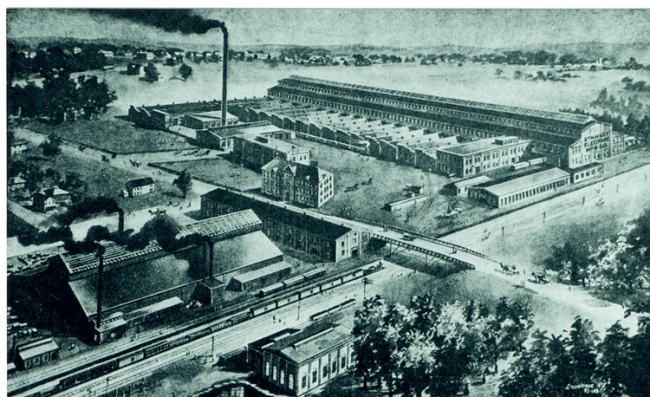
The Morningside Plant in 1903, courtesy Pittsfield G.E. News, August 31, 1973
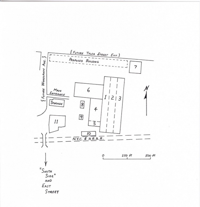
The "North Side" of the Morningside Plant in 1908, courtesy Pittsfield G.E. News, August 31, 1973
The preceding page shows the building layout of the plant in 1908, just after it became the Pittsfield G.E. Works. The area shown is that located north of the New. York Central and Hudson River Railroad tracks. This was actually the right-of-way for the Boston & Albany Railroad, which was owned by the NYC&HRRR. These tracks do still exist, and serve Conrail and Amtrak trains which run between Boston, Mass. and Albany, N.Y.
The identified buildings served the following functions in 1908:
Buildings 1-2-3
These were the main transformer assembly and testing bays. Building 1 was constructed in 1900, and Buildings 2 and 3 were added around the time that the plant became a part of G.E. These buildings still exist today.
Building 4
This was the main winding area for the larger sizes of transformers. It also still exists. This was also the assembly area for small types of transformers.
Building 5
This was the main shipping area. It was served by a railroad siding running along its south side; this siding also ran through the south end of the Building 1-2-3 complex. This building eventually housed offices and the "copper shop", and still exists.
Building 6
This was the area in which the various types of insulation (such as pressboard, etc.) needed in the transformers was prepared. It still exists.
Building 7
This was where the thin laminations of steel needed to build up the magnetic cores of the transformers were fabricated. This building served several other functions in later years. It still stands, but is somewhat derelict.
Building 8
This was the Laboratory building where the development of transformer insulation materials, and the high voltage testing of same, was carried on. It still stands, but is also somewhat derelict.
Building 9
This no longer exists; it was a storage facility for the oils used in transformers for insulation and cooling.
Building 10
This was identified as a Carpenter and Pattern Shop, and no Longer exists.
Building 11
This was the Brass Foundry and Tank Shop, for the production of brass electrical fittings and the fabrication of the iron tanks which held the working parts of the transformers. The site is presently occupied by a new Building 11 dating from the 1960's.
The building near the Main Entrance, designated as "Storage", was soon after replaced by Building 16; this became the main Engineering and Drafting building for the transformer operation. It still stands.
Around this same time (1909-10), an addition known as Building 13 was constructed at the south end of the Building 1-2-3 complex; it is now gone. Also, a new Tank Shop (Building 14) was constructed to the east of Building 7, and a new shop for core steel (Building 15) was added to the north of Buildings 4 and 6. In 1914, a larger transformer assembly and testing facility known as Building 12 was begun to the east of Building 3. All of these latter buildings still exist.
Also, the area designated as "Proposed Building" became Building 17. Originally, this also served as a Tank Shop; however, for many years after that, it was the main winding facility where most of the large transformer windings were constructed on winding "lathes". This building still stands.
In 1908, the major buildings on the "South Side" of the railroad tracks were:
- an iron foundry, using cupola-type melting furnaces, for the production of cast iron transformer tanks (in later years, the tanks would be made of welded steel plates). This was on the site of the present Building 33.
- a building for producing molded-type insulations, and a building for the kiln-drying of wood insulation materials.
- a building for the manufacture of fan motors. This became the site of Building 26 which was razed in 1988.
- the original Power House for the plant. This became Building 31 which still stands, but is now derelict.
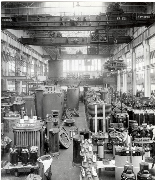
Building 2 in 1910, Hall of Electrical History
The 1908 layout of the "North Side" of the plant shows a curve in the street line to the north of the railroad bridge. Eventually, this became the intersection of Woodlawn Avenue and Kellogg Street. Also, this became the site of the "North Gate", a new main entrance to the plant.
The establishment of North Gate coincided with the construction of a main office building, Building 42, in 1911. This building was directly across from (to the west of) Building 11. Two years later, an addition was constructed running west along Kellogg Street. This was known as Building 43 and contained more office space. Both Buildings 42 and 43 still exist, but are unused.
Along with the main offices for the plant, there was some production area in Building 42; this was mainly devoted to the manufacture of heating devices. Also, there was a Telegraph Office with connections to both the Postal Company and Western Union, along with a line directly to the Schenectady G.E. plant. In addition to offices, Building 43 contained production area devoted to the manufacture of lightning arresters, a tool room, and space for the training of Apprentices.
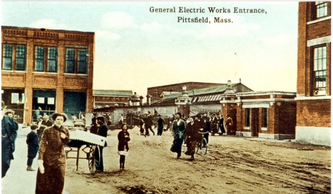
North Gate with Building 42 at right courtesy of Judy Rupinski, Pittsfield, MA
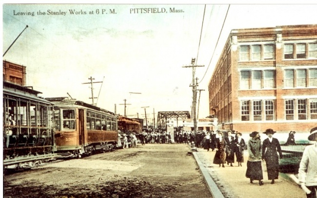
Woodlawn Avenue and North Gate in 1913 courtesy of Judy Rupinski, Pittsfield, MA
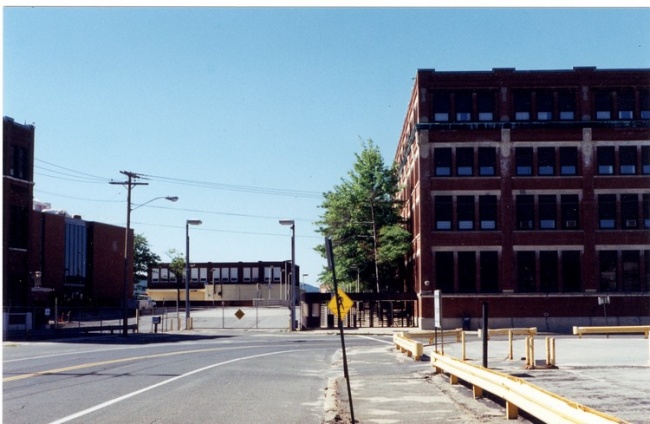
Woodlawn Avenue and North Gate in 1996 photo by author
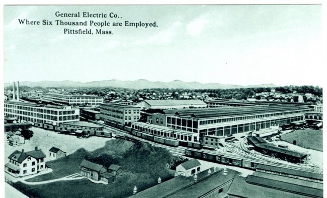
View of plant from southeast (circa 1912) courtesy of Judy Rupinski, Pittsfield, MA
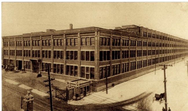
Buildings 42 and 43 in 1914, G.E. Current News, May, 1914
Chapter 2: The Electric Power System
An interesting aspect of the electric power system in the Morningside plant is that it was not the standard three-phase type of power which is universally used now. The generation and distribution was via a system known as "two-phase".
William Stanley designed and built a great deal of two-phase equipment during the 1890's, partly because of a belief in its superiority over three-phase, but also to avoid patent infringement problems with General Electric and Westinghouse who both used the three-phase system.
In fact, three-phase is decidedly superior for power distribution purposes. Thus, the old two-phase systems have gradually faded out of existence. However, two-phase power was so firmly entrenched in the Pittsfield plant that remnants of it still exist today! This has to do with the existence of old two-phase motors which have never been replaced.
Three-phase power consists of three alternating-type voltages intermingled on three wires. It can be proven mathematically that it is the most efficient system for transferring large amounts of electric power from one place to another, considering the weight of copper which is necessary to do so.
However, in the early 1890's, the understanding of the complexities of "polyphase" (more than one phase) systems was still limited. In particular, there were problems in learning how to regulate the three voltages in a three-phase system in order to keep them all at a constant level. Varying voltage levels severely reduced the expected life of the early incandescent lamps.
Since the basic two-phase system consisted of two completely separate two-wire single-phase circuits, independent regulation of each circuit was relatively simple. This was the main reason that Stanley, as well as others, advocated the use of the two-phase system.
The two-phase system which was adopted in the plant in Pittsfield was somewhat unusual in that only three wires were used instead of four; one wire served as a common for the two single-phase circuits. The two voltages in a two-phase system are at ninety electrical degrees to each other.
Thus, when one wire is used as a common return, the current which flows in it is 41 percent greater than the current in the other two wires, even when feeding a balanced load such as a motor.
Because of this, feeder cable runs in the plant often consisted of two cables of one size plus a third cable which was roughly fifty percent larger in cross-section. However, sometimes it was apparently easier to deal with just one size of cable; in such situations, four cables were run and two were paralleled to use as the common. Obviously, this led to some waste in the total amount of copper used.
The original plant Power House dated from 1900 when the Stanley Company moved from Renne Avenue and Clapp Avenue in Pittsfield. The first generators installed were two-phase machines. By 1950, there were still a couple of two-phase generators (of later vintage) being held in reserve for emergencies. However, the active generation by that time was all three-phase. Over the years, phase-changing transformers had' been installed in some of the electrical substations around the plant to provide two-phase power to old motors still in use. As of today (1997), there are still one or two of these special transformers in use for this same purpose!
The windings of the phase-changing transformers were of a special design developed by G.E. engineers which would have allowed the transformers to be converted to straight three-phase transformers at some pertinent time. Doubtless, these engineers would have been surprised if they knew that such a changeover was destined never to happen!
The two-phase generation and distribution voltage was originally chosen to be 2300 volts, and this was never changed through the years. In 1900, and for some years after that, all of the generators in the Power House were belt-driven from reciprocating steam engines. In later years, of course, the old engines were slowly replaced by steam turbines, and the generators replaced by more modern designs.
The Power House was erected near to Silver Lake, so as to have an adequate supply of cooling water for condensing the steam. Eventually, this became known as Building 31.
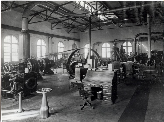
Early Power House Interior: Hall of Electrical History
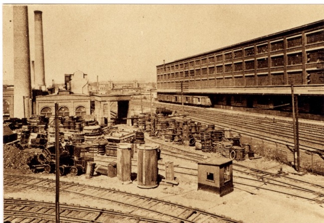
View west from railroad bridge in 1922 (Building 31 on left): G.E. Current News, April, 1922
Synopsis of Power House History
- 1900 - original power house constructed
- 1907, 08 - two 500-kw, two-phase vertical turbines installed
- 1910, 11 - two 1500-kw, two-phase four-stage turbines installed
- 1915 - 2500-kw, two-phase horizontal turbine installed
- 1930's - experimental mercury turbine installed
- 1941 - 3000-kw, two-phase horizontal turbine installed
- 1946 - two 7500-kw, three-phase horizontal turbines installed
- 1950 - 7500-kw, three-phase mercury turbine installed
- 1960 - mercury turbine removed
- 1970 - power house ceases generation; provides steam only
For some time prior to 1970, General Electric had a cogeneration agreement with the Western Massachusetts Electric Company whereby they purchased any excess power available from the Power House.
During the 1980's, it was determined that the Power House could not be brought up to existing pollution standards. Accordingly, G.E. instigated the construction of a new cogeneration plant on property which they owned to the east of the main plant. The plant Power House was then completely shut down. Today, the new plant sells electric power to Northeast Utilities, and sells steam for heating purposes to General Electric.
When in full operation, the plant Power House provided high pressure process steam, low pressure heating steam, and compressed air for manufacturing use.
By 1915, major substations in the plant were located in, or near, Buildings 4, 12, 15, 41, 42, and 43 on the North Side, and Buildings 26, 32, and 33 on the South Side. In addition, there was a separate set of feeders from the Power House to the main transformer testing facility in Building 12 (because of the large amount of power required by that operation).
As a matter of interest, all of the steel buildings in the plant were connected electrically by means of a large diameter copper cable; this, in turn, connected to a grounding plate at the bottom of nearby Silver Lake!
The substations served to step down the voltage from the Power House to:
- 110/220 volts single-phase
- 440 volts three-phase
- 550 volts two-phase
The three-phase system, as it evolved in the plant, operated at 13,800 volts (13.8-kv). In 1936, switch-gear was installed in the Power House in anticipation of an interconnection between the plant and the lines of "The New England and Turner's Falls Power Company". These were 115-kv lines which terminated at the Silver Lake Station of the Pittsfield Electric Company.
Two Pittsfield-built transformers were installed near Silver Lake. These had dual secondary windings. One winding connected with the 13.8-kv three-phase plant power system, while the other winding connected: with the 2300-volt two-phase plant power system (via a phase-changing winding connection).
The mercury turbine installation referred to above was the result of development work in the use of mercury vapor as a more efficient alternative to high pressure steam for driving turbines. Complications in the technology, however, led to its eventual abandonment (today, such a concept would probably be unacceptable due to the usage of vast amounts of toxic mercury!).
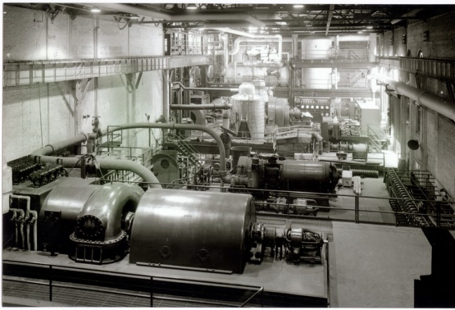
Power House interior in 1949 courtesy of General Electric Company
Chapter 3: The "Current News"
During the years 1913 through 1931, the Pittsfield G.E. plant newsletter was known as the "Current News". This was a glossy magazine-style publication which was printed on a monthly basis. It is not known exactly why it ceased publication in 1931, but it may have been a casualty of the Great Depression; it was probably fairly costly to produce. After a lapse of three years, it was replaced by a newspaper-style publication known simply as the "Pittsfield G.E. News".
The following is a compendium of interesting items taken from the "Current News". The emphasis is on technical developments related to transformers as well as items relating to expansions and changes within the plant. However, there are also miscellaneous "tidbits" of information which deal with people-related and community types of events.
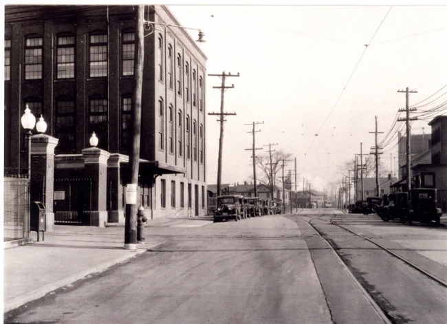
"South Gate" at East Street during the 1920's courtesy of General Electric Company
1914:
- The High Voltage Engineering Laboratory was formed.
One of the many brilliant technical men associated with the Pittsfield plant over the years was A.M. Gifford, who headed the Laboratory operation for 45 years. Gifford was instrumental in the quest for the development of improved transformer core steel which drastically cut magnetic losses.
Known as silicon steel, this material was actually first developed in England in 1907 by Sir Robert Hadfield.
Gifford also promoted the use of Pyranol, a non-flammable transformer insulating fluid which was eventually banned in the 1970's, being a suspected carcinogen.
He was heavily involved in development work through the years which eventually led to the creation of the G.E. Plastics Operation, the only vestige of General Electric remaining in Pittsfield in 1997.
Finally, he was instrumental in the development of Calrod heating units, still used in conventional electric ranges and ovens. For many years, these were manufactured in a building on Columbus Avenue in Pittsfield.
- Construction was begun on Building 12 which was to become the main transformer assembly and testing facility for large transformers.
- A new Works Restaurant, located on Kellogg Street near the North Gate, was opened.
- Flatirons were being manufactured in a section of Building 43.
- The G.E. Band was organized.
- The quality of the plant's drinking water was being questioned!
1915:
- An addition (known as "17Ext") was made to Building 17, located near the corner of Tyler Street and Woodlawn Avenue. Originally built in 1910, Building 17 had become the Tank Shop where steel transformer tanks were fabricated. The original Tank Shop had been on the site of the present Building 11.
- G.E. sponsored an elaborate production of Gilbert and Sullivan's "The Mikado", at the Colonial Theatre on South Street in Pittsfield.
- The Works Restaurant began serving breakfasts in addition to other meals.
1917:
- The manufacture of fans and motor armatures was begun in a building on Columbus Avenue in Pittsfield, which had been purchased in 1916.
- The first commercial testing of transformers in the new Building 12 facility was begun.
- Lightning arresters were being manufactured in Building 41, heating devices (including Calrod units) in Building 43, and small motors in Building 26.
1918:
- The General Electric Athletic Association, known as the G.E.A.A., was formed.
- A new Employees' Food Store was opened in Building 42.
- The April, 1918 issue of the "Current News" was a special Liberty Loan issue. The Liberty Loan goal for the Pittsfield plant was set at $3,000,000.00. This was basically a loan to the U.S. Government to support U.S. involvement in World War I. War Savings Certificate Stamps (known as "Baby Bonds") were a means of making smaller contributions for those who could not afford to purchase a full Liberty Loan Bond all at once.
- In September, the Hon. Crawford Vaughan, ex-premier of South Australia, gave a "pep talk" to employees of the Pittsfield plant. At the conclusion of his speech, he said "I ask you to give three cheers for the Boys at the Front". Three cheers were given, followed by great applause and a rendition of "The Star-Spangled Banner" by the Works Band. In attendance were Pittsfield notables Miss Mira Hall, proprietress of Miss Hall's School in Pittsfield, and her niece, Miss Margaret Hall.
Employees' Food Store in Building 42 G.E. Current News, February, 1920
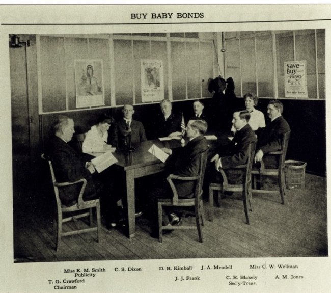
Pittsfield Works War Savings Stamp Committee G.E. Current News, April, 1918
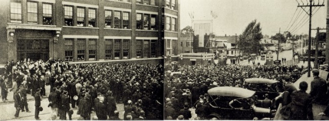
Flag-raising at North Gate in 1918 G.E. Current News, September, 1918
1919:
- The plant's telephone exchange was located on the top floor of Building 16.
- A new Machine Shop started operations in a section of Building 15. The original Machine Shop had been located at the north end of the Building 1-2-3 complex, an area known as the "hill" because it was on a higher level than the rest of the building due to the rise in the land beneath.
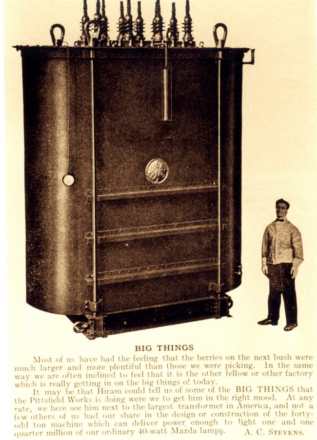
The largest transformer in the United States in 1919 "can supply 1.5 million 40-watt Mazda lamps" (60,000-Kva), G.E. Current News, September, 1919
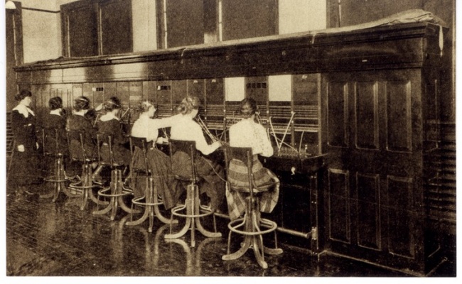
New Telephone Exchange in Building 16 (1919) G.E. Current News, February, 1919
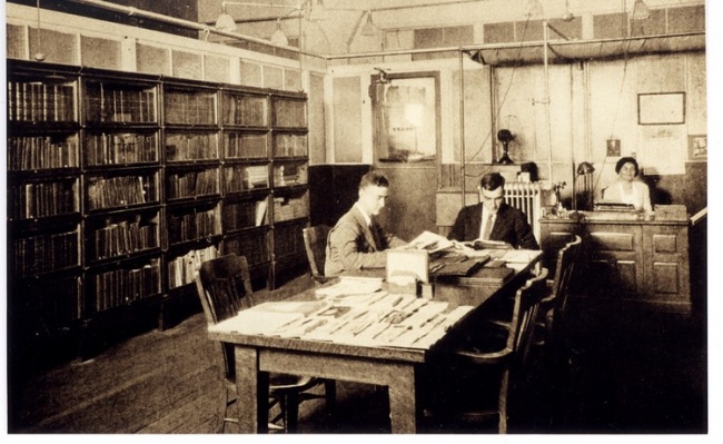
Works Library on third floor of Building 42 G.E. Current News, October, 1922
1920:
- A new auditorium in Building 16 was dedicated.
- G.E. sponsored an oriental musical revue at the Colonial Theatre called "Jappyland"!
- An article by a former New York City resident sang the praises of life in the Berkshires because living and working in "the City" meant a long commute every day and very high prices!
1921:
- A new Building 17 was built; this was to become the Winding Room where most of the large transformer windings were assembled for many years. Building 14 (originally built in 1909) had just been remodeled to become the new Tank Shop.
1922:
- A.B. Hendricks first produced a one million volt, three-phase arc in the High Voltage Lab.
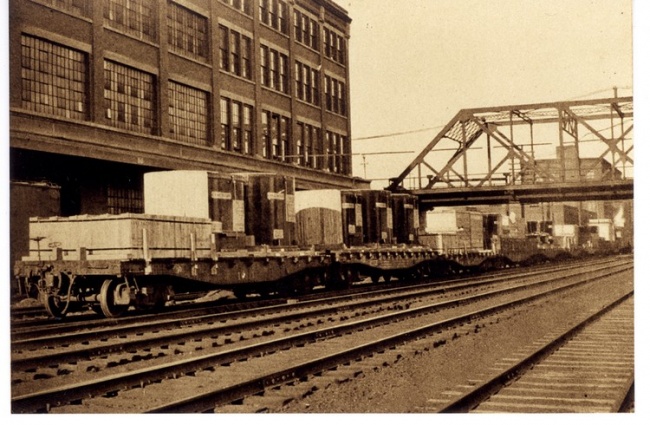
11,000-Kva transformers being shipped to Yokohama, Japan (1922), G.E. Current News, August, 1922
1923:
- The Stanley Library was created and housed in Building 16. This library combined a former Works Library in Building 42, a Laboratory library in Building 8, and one thousand volumes from William Stanley's personal library. The latter was a gift from Stanley's widow, Lila C. Stanley. The idea for the combined library was that of Cummings C. Chesney.
In 1948, the Stanley Library was moved back to Building 8 following the construction of a new floor in that building to vertically divide the "high bay" laboratory area there. General Manager Robert Paxton arranged for a $50,000 appropriation to accomplish this.
In 1966, the Library was moved to the newly-constructed Building 11. This building housed facilities for visitors, and General Manager Robert Gibson recognized that the presence of the Library would contribute to the impression that this was a top-notch research facility.
- According to Samuel Sass, venerable Librarian during the latter years of the Pittsfield G.E. operation, an interesting early use of a small building in the plant (Building 43A) came to light when he was looking for storage space for library books which were not often requested.
This building had been equipped with shower stalls and foot baths which, it turned out, dated from the days when lead oxide pellet lightning arresters were manufactured. The employees were required to shower and change clothes before going home so as not to take the lead dust with them!
This procedure had been instituted by a pioneer in the field of industrial toxicology, Dr. Alice Hamilton. She had been hired by Gerard Swope, president of General Electric, in 1923. In her capacity as Medical Consultant to the company, she recommended this and other procedural changes at the Pittsfield G.E. facility.
Dr. Hamilton died in 1970 and, as reported in the Berkshire Eagle of February 18, 1996, she has been honored by the United States Postal Service by the issuance of a stamp as part of its Great American series.
- A new Wood Shop went into operation, located in Building 7D.
- Dial telephones were installed in the plant.
- A 110-Kv double-circuit transmission line was placed in operation which connected the Pittsfield Electric Company with a hydroelectric plant at Turner's Falls, Mass. This line terminated at the Silver Lake Station of the Pittsfield company, adjacent to the G.E. Power House. It was about this time that the first ties were made between the G.E. power system and that of Pittsfield Electric. The 110-Kv transmission line is still in operation.
1924:
- The Stanley Club, a G.E. business-oriented social club, was organized in Pittsfield.
- The construction of Building 12X was announced. This was referred to as the "super-transformer building" for the assembly and testing of the largest transformers. It was built as an extension of the east side of the existing Building 12.
- Concrete reactors were being manufactured in Building 7B. These had been developed in 1910 and consisted of air-core reactor structures supported by a poured concrete framework. They were (and still are) used primarily as current-limiting devices in power systems.
- One million volt Test Sets, each using three cascade transformers, were built for the G.E. Works in Philadelphia, and for Commonwealth Electric, a mid-west utility.
- The first Load Ratio Control was built. This device allowed transformer voltage output to be adjusted under load. The concept had been developed by G.E. engineers.
Induction-type regulators were being manufactured in Building 19. This had been the case since 1912; from 1908 until 1912, they had been manufactured in Buildings 1-2-3, in the area known as the "hill" at the north end.
1925:
- The main Receiving Department for the plant was located in the basement of Building 42. This location allowed for direct access to the adjacent railroad tracks.
Fan motors were being manufactured in a part of Building 43(along Kellogg Street).
1926:
- The Wire Department was located on Columbus Avenue in Pittsfield.
- A new Laboratory facility was built; this was an addition to Building 8, known as "8-Ext".
1927:
- Capacitors were being manufactured in a part of Building 42.
- The Works Restaurant was now operating in a section of Building 43, known as "43B". A cafeteria for the "South Side" was operating in Building 27.
- The Power House was flooded to within one inch of the high voltage busses when Silver Lake overflowed!
- Edward Kopf graduated from the Pittsfield G.E. Apprentice Program, having joined it in 1923.
Mr. Kopf has quite a few interesting recol-lections of life in the Apprentice Program, as well as the Pittsfield plant in general.
The Apprentice Program operated out of part of Building 26, located near East Street. It utilized two classrooms plus a fully-equipped machine shop, as well as two full-time instructors.
Apprentices attended one two-hour class each working day. During the first year of the program, they learned how to operate every one of the machines in the shop. Then, they were sent to areas related to their particular line of interest: drafting, tool-making, pattern-making, maintenance, or engineering. There were both three and four year courses, and an entrance exam was mandatory.
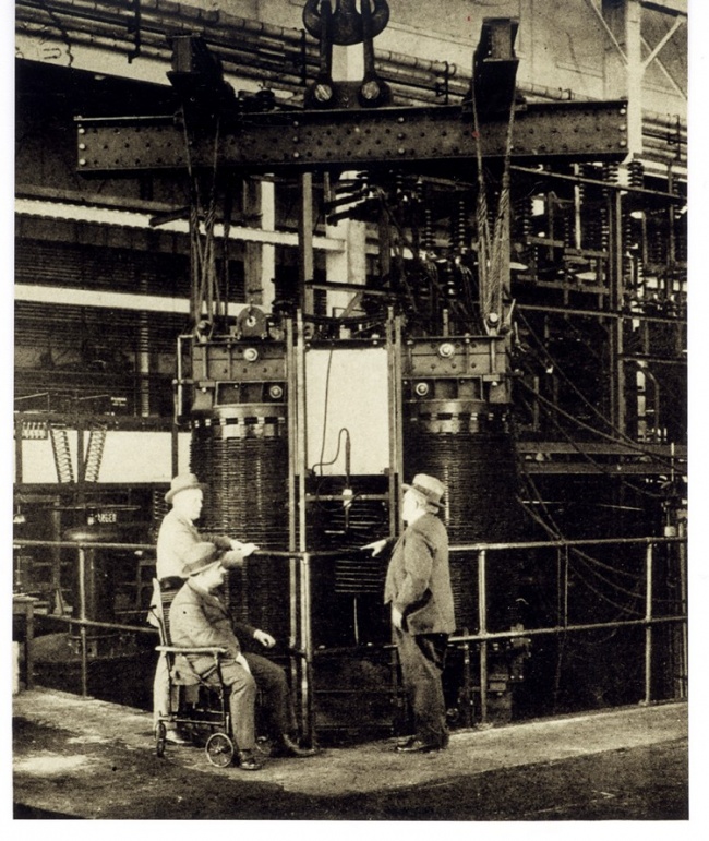
Works Manager Cummings C. Chesney, along with Guiseppe Faccioli (in wheelchair) and W.S. Moody, inspect the largest single-phase transformer built as of 1926 (water-cooled, 60-cycles, 28,886-Kva, 100 tons for the Wallenpaupack Substation of the Pennsylvania Power and Light system; the three-phase bank of which it was to be a part was rated for 220-Kv to 66-Kv with an 11-Kv tertiary winding), G.E. Current News, January, 1926
Apprentices were able to obtain experience working in any of the different departments in the plant: principally Power Transformer, Distribution Transformer, Regulators, Load Ratio Control, Foundry, Tool Room, Lightning Arresters, and Bushings.
Starting pay on the four-year course was $9.60 per week for a 49-hour week. Exams were given every six months and, if passed, the Apprentice received a raise of two cents per hour!
Subjects taught during the course included Mechanical Drawing, Shop Math, Trigonometry, Mechanics, Mechanisms, Strength of Materials, Gear & Cam Design, Advanced Trig, Electricity (both AC & DC), Tool Design, and Machine Design.
Upon graduation from the course, each Apprentice received (personally) a large diploma from the Plant Manager. Also, in Ed Kopf's case, this diploma allowed him (in 1957) to obtain his Massachusetts License as a Professional Mechanical Engineer simply by taking a few night courses!
Other recollections of Mr. Kopf's include the fact that two small steam locomotives were used to haul materials around the plant in those days. Tracks ran up the hill from South Gate (at East Street), over the railroad, and out North Gate onto Woodlawn Avenue; then back into the plant at Building 17 and on to the Tank Shop (Building 14). In the winter, when ice and snow were on the tracks coming up from South Gate, men had to run ahead of the locomotive with buckets of sand to throw on the tracks for traction! Sometimes, with big loads, both locomotives had to be used running in tandem.
Also, during that era, the twelve to fifteen thousand employees in the Pittsfield plant received their pay in cash (no checks). Money was picked up at the First Agricultural Bank in Pittsfield and brought to the plant in a large safe mounted on a flatbed truck. This was a battery-operated truck, and only enough charge was put into the batteries to make the trip to the bank and back again! Armed guards from the plant accompanied the truck, and additional armed guards from the bank were on hand for the loading of the money into the truck.
The truck was driven into a freight elevator in Building 42 and taken up to the Payroll Department. Each department in the plant had a fold-up wire cage which was set up at a designated spot on pay day. The money was distributed to these various locations by other trucks. At each stop, the money and a payroll clerk were left in the cage. Pay envelopes were arranged by clock number, and it took only ten or fifteen minutes in each department to distribute all of the pay.
1928:
- An article reported that the Pittsfield Works employed 7000 people, covered 153 acres, and produced:
"transformers, voltage regulators, cut-outs, current limiting reactors, heating devices, lightning arresters, capacitors, and single-phase motors."
- L.V. Bewley, world-renowned expert in surge phenomena and lightning-related disturbances on high voltage transmission lines, came to work at the Pittsfield plant from Schenectady General Electric.
- The first oscillogram of natural lightning was taken by personnel of the High Voltage Engineering Laboratory at Lake Wallenpaupack, Pa.
- A major civic improvement in the vicinity of the Pittsfield plant was the paving of East Street!
- An article reported that an oil-filled transformer had burned up after seven years in service. However, inspection showed that the mid-western utility customer had never filled it with oil, and that the instruction manual was still hanging inside the tank!!
(This is an indication of how equipment of this era was over-designed; the unit probably burned up because the load had slowly increased over the years.)
1929:
- A new Building 34 was built, on the South Side of the plant near Silver Lake, which replaced an earlier building used mainly as a Pattern Shop for the adjacent Foundry in Building 33. The new Building 34 is still there.
- Nearby Building 36 housed the Molded Insulation Department.
- Silver Lake Boulevard was constructed around Silver Lake.
1930:
- Thyrite (G.E. trademark) was developed. This is a non-linear resistance material composed of a silicon carbide compound. It is used in lightning arrester and surge suppressor type devices to "clamp" over-voltages, but prevent the normal power system voltage from causing a current flow through it.
- The first commercial Impulse Test was performed on a transformer. This test simulates the effect of lightning-related surges which the transformer may be subjected to in service and demonstrates that the transformer insulation will withstand such mistreatment.
- Building 62 is built south of East Street. This functioned as the Gas Plant, producing various types of bottled gas for use in production processes.
- A new Building 14 is under construction to replace the earlier Tank Shop. This was one of the first welded steel buildings in the country; prior to this, steel buildings were of riveted construction.
- The five-day work week was introduced, giving employees a full weekend off.
- Safety shoes were introduced.
1931:
- F.W. Peek, Jr. becomes the Chief Engineer of the Pittsfield Works.
- The new Tank Shop (Building 14) is placed in operation; it includes a cafeteria. An Open House is held in June.
- Four network transformers are built for the Pittsfield Electric Company, and installed on West Street, Elm Street, Worthington St., and Francis Avenue in Pittsfield.
The next chapter contains biographies of several of the notable professionals associated with the Pittsfield, plant over the years.
Mrs. Irma Giegold, of Pittsfield, recalls that her father, Arthur Palme, was a friend and co-worker of all these gentlemen. Mr. Palme worked as an engineer from 1913 until his death in 1949. In particular, Mr. Palme was hired by Works Manager Cummings C. Chesney in spite of the fact that, at the time, Mr. Palme could not speak a word of English!, In fact, during World War I, he was restricted to his desk, the men's room, and the Works Restaurant because he was considered to be an "alien enemy". When he became a U.S. citizen in 1919, his co-workers decorated his desk with an American flag and threw a party. He was then finally given full access to "the shop"!
Eventually, Mr. Palme received several patents. He was also well received by the shop workmen because. he spoke their language, which was predominantly Italian at the time. During Prohibition, he was often favored with gifts of homemade wine!
Mrs. Giegold later became a Pittsfield G.E. employee herself. Once, her father "spirited" her into the High Voltage Laboratory to see a demonstration of artificial lightning which was being staged especially for then Governor of Massachusetts, James Curley.
Chapter 4: Biographies
Guglielmo C. Camilli
Guglielmo Camilli was a native of Rome, Italy; he received his engineering degree from the Royal Polytechnic School of Turin in 1922. In 1926, he began his career with General Electric as a Development Engineer in Pittsfield.
In 1956, he was named Supervisor of Power Transformer Advance Product Engineering. By 1958, he had received a total of fifty-five patents, more than anyone else in the General Electric Company at the time. He was twice the recipient of the Coffin Award, the highest employee honor bestowed by General Electric. He was the author of a book on the subject of transformer engineering, and authored many technical papers throughout his career.
Camilli was an avid amateur astronomer. He ground his own lenses and built his own telescopes. He was a member of the volunteer Pittsfield G.E. Speakers Bureau; as such, he presented a very popular talk around the country which was called "A Trip through the Universe". He predicted that the United States would reach the moon by 1967 (not far off!). He also used his immense knowledge of transformer insulation structures and cooling methods to design a "transformer for use on the moon" in 1955! He operated his own personal observatory at his home on East New Lenox Road in Pittsfield.
In 1928, he constructed a home-brew television set for his own use. This was the first television of any type which was seen in Pittsfield.
Cummings C. Chesney
C.C. Chesney, a native of Pennsylvania, was born in 1863. Following his graduation from Pennsylvania State College in 1885, he taught mathematics and chemistry until becoming associated with William Stanley in 1888, in Great Barrington, Mass., as a chemist and engineer.
He followed Stanley to the United States Electric Lighting Company in Newark, New Jersey (a subsidiary of the Westinghouse Company) in 1889. He then became associated with the Stanley Electrical Manufacturing Company in Pittsfield as an electrical engineer in 1891. He was the "C" in the S.K.C. system marketed by Stanley.
In 1903, when the Stanley Company became a subsidiary of General Electric, Chesney was advanced to the position of Vice-President and Chief Engineer. In 1907, when the company became the Pittsfield Works of General Electric, Chesney was named Works Manager. He continued in this capacity until 1927 when he was named a vice-president of the General Electric Company.
While with Stanley, he personally supervised the design of S.K.C. equipment, including the first revolving field type of alternator used in this country.
Chesney was very active in local business activities as well as civic affairs. He was active in the Boys' Club of Pittsfield, and was a member of the Chamber of Commerce there.
In 1921, he received the Edison Medal from the American Institute of Electrical Engineers, and he served as President of that organization from 1926 to 1927. The Edison Medal is the highest award given to an electrical engineer, and is for meritorious achievements in electrical science, engineering and art.
Cummings Chesney retired in 1930 and died in 1947. He was survived by his widow, Elizabeth, four daughters, a son, and eleven grandchildren.
Giuseppe Faccioli
Giuseppe Faccioli was born in Rome, Italy in 1877 and graduated with high honors from the Institute of Technology in Milan in 1899 as a mechanical and electrical engineer. He came to the United States in 1902 and obtained a position with the New York Edison Company (the ancestor of Consolidated Edison in New York City). One year later, however, he transferred to the employ of the Interborough Rapid Transit Company, the builders of the first subway system (the IRT) in New York City.
Then, in 1904, he went to work for the Crocker-Wheeler Company in Ampere, New Jersey (near East Orange). Crocker-Wheeler had been building rotating electrical machines for the Stanley Company and, as a result, he came into contact with William Stanley. This led to his joining Stanley in Great Barrington (by this time, the Stanley Company in Pittsfield was a subsidiary of General Electric, and Stanley himself had gone back to Great Barrington to engage in other ventures).
In 1908, Mr. Faccioli transferred to the Engineering Department of the Pittsfield Works of General Electric. In 1911, he was appointed Assistant Chief Engineer and, in 1914, he became Chief Electrical Engineer of the Pittsfield Works. In this capacity, over the years, he became intensely interested in high voltage power transmission work, and contributed heavily to the development of high voltage transformers and lightning arresters.
He was very active in the American Institute of Electrical Engineers and was the author of highly technical papers on subjects such as electrical transients.
Mr. Faccioli retired in 1930; by that time, he had been confined to a wheelchair for many years. A presentation in honor of his retirement was made at his home on East Housatonic Street in Pittsfield; this house still stands today.
Allan Barringer Hendricks, Jr.
Mr. Hendricks was born in 1874 in Duchess County, New York State. In 1900, he completed a special three-year course at the Lawrence Scientific School of Harvard University. In September of that year, he entered the employ of the Stanley Electrical Manufacturing Company in Pittsfield where he worked on the assembly of switchboards and in instrument test.
In 1901, he moved to the Morningside Plant of the Stanley Company in Pittsfield and spent a year in generator and transformer test. He then began to specialize in the areas of insulating materials, line insulator design, and the measurement of high voltage line losses. Between 1905 and 1911, he organized the testing laboratory, acting in the capacity of engineer of insulating material development.
In 1906, he designed and built the first transformer devoted to the testing of insulation; it was capable of producing voltages up to 150,000 volts. In 1911, he transferred to the Transformer Engineering Department as a development engineer in the design of high voltage transformers and allied devices. Under his guidance, all of the transformers used in high voltage testing were designed, providing up to 1,000,000 volts three-phase and 1,500,000 volts to ground (single-phase).
In 1922, he devised the 1,000,000 volt three-phase arc which remained a mainstay of public demonstrations for the next fifty years or so.
He was also involved in the development of equipment such as high current testing transformers, cable testing apparatus, x-ray transformers, high frequency transformers, power and filament transformers for vacuum tube rectifiers, and air-blast type power transformers for use by the Interborough Rapid Transit Company of New York City (builders of the first subway system there).
In later years, he was also intimately involved with the design of impulse generators for laboratory testing with simulated lightning surges.
Dr. Karl B. McEachron
Dr. McEachron was born in Hoosick Falls, New York in 1890. He graduated from Ohio Northern University in 1913 with both E.E. and M.E. degrees. That same year he joined the General Electric Company as a student engineer on the test course. In 1914, he returned to Ohio Northern as an instructor in electrical engineering. In 1918, he became an instructor and research associate at the Engineering Experiment Station of Purdue University where he received an M.S. degree in Electrical Engineering.
In 1922, he returned to G.E. to take charge of the research and development section of Lightning Arrester Engineering Development in Pittsfield. In 1933, he was appointed engineer in charge of the High Voltage Engineering Laboratory. In 1945, he was appointed Assistant Works Engineer. In 1947, he was named the Assistant Manager of Engineering of the Transformer and Allied Products Division. In 1949, he was appointed Manager of the TAP Division.
He received the appointment of Manager, Laboratory-Engineering Department in 1952, and, in 1953, was named as the Consultant of Professional Employee Relations for all technical employees in the Engineering Services Division of the General Electric Company.
He originated and supervised the lightning investigation at the Empire State Building which yielded a vast amount of valuable data on natural lightning. Also, under his direction, 10,000,000 volt discharges were produced by impulse generators at the 1939 New York World's Fair, and the new High Voltage Laboratory building (Building 9) was opened in Pittsfield in 1949.
Dr. McEachron was a recognized authority on lightning, world-wide. He was often called upon to testify in cases of lightning-caused injuries and damage. In 1940, he coauthored the book "Playing with Lightning", and, in 1948, he wrote the article "Lightning and Lightning Protection" for inclusion in the Encyclopedia Britannica. He was also the author of many technical papers on the subject of lightning and related topics.
Walter Sherman Moody
W.S. Moody was born in Chelsea, Mass. in 1864. In 1887, he graduated from M.I.T. with a degree in Electrical Engineering. He then became an instructor in physics and electrical engineering at M.I.T.
In 1888, he became an assistant engineer at the Thomson Electric Welding Company in Lynn, Mass. This company was started by Elihu Thomson of the Thomson-Houston Electric Company (Thomson was the inventor of the electric welding process). In 1892, The Thomson-Houston Company was merged with the Edison General Electric Company to form the present General Electric.
Mr. Moody then joined the Thomson-Houston Company in 1892, the year of the merger. After General Electric was formed, he became the Chief Engineer of the Lynn Transformer Works of General Electric. In 1897, he moved to Schenectady and assumed the same position at that plant.
In 1908, after the Stanley Company had become the Pittsfield Works of General Electric, Mr. Moody moved here to continue his career. He came to be known as a pioneer in transformer design, and he retired as a Consulting Engineer in 1931.
Among his accomplishments included the design and development of the extremely successful Type 'H' distribution transformer, a basic design for air-blast type transformers, and, perhaps most notably, the development of a practical process for rolling silicon steel to be used for the construction of low loss transformer cores.
Mr. Moody died at home in Pittsfield in 1938, at the age of seventy-four.
K. K. Paluev
Konstantin K. Paluev was born in Russia in 1894 and was educated as an engineer at the Polytechnic Institute of Peter the Great in Petrograd. He came to this country in 1916 as a representative of the Czarist government to inspect United States ammunition bound for Russia. He often declared that the Russian Revolution "set him free" in this country.
He came to the Pittsfield G.E. plant in 1919, and his contributions to the design of transformers were enormous.
Paluev was responsible for the development of the "non-resonating" winding configuration in transformers. This was a way of designing windings with electrical_ characteristics such that they would be much less susceptible to the very high surge voltages produced by lightning strokes. He accomplished this in the 1920's, and it was the only way in which transformers were able to be designed for operation at voltages as high as the upper voltage limit at that time, which was 230-Kv.
In 1930, he played a leading role in the development of forced-oil cooling for large power transformers. This development was to be of great advantage in the design of large, high power transformers needed for various aspects of the war effort during World War II, as well as the large capacity transformers needed during the post-war period.
He was noted for his belief in the doctrine of "collective genius". This concept dealt with the ability of a group of people, in a free society, to be able to accomplish far, more than their individual talents would indicate was possible. He considered this to be the prime reason for American productivity and inventiveness.
Paluev died in 1958, at the age of sixty-four, in Pittsfield General Hospital a month after having received a severe electrical shock.
Frank W. Peek, Jr.
F.W. Peek was born in California in 1881. He graduated from Leland Stanford University in 1905 with a Bachelor of Arts degree, and from Union College in Schenectady with a Master's Degree in Electrical Engineering in 1911. He entered the employ of the General Electric Company in 1905 as a test man in Schenectady. A year later, he was placed in charge of special testing in engineering research.
Mr. Peek became interested in high voltage research about 1906, when this was a very new subject. Funding was hard to obtain, so he set up a laboratory in an old boxcar in a remote corner of the Schenectady G.E. plant. Periodically, he would discuss the results of his work with the famous G.E. scientist, Dr. C.P. Steinmetz. In 1909, he was one of the first young engineers to join the newly-formed Consulting Engineering Department of the G.E. Company, under Dr. Steinmetz.
In 1916, Mr. Peek was transferred to Pittsfield where high voltage research work was underway. Soon after Dr. Steinmetz built his first lightning generator in Schenectady, Mr. Peek was building similar machines in Pittsfield, but at ever increasing voltages.
In 1931, Mr. Peek was named Chief Engineer of the Pittsfield Works, succeeding Giuseppe Faccioli who had recently retired due to ill health.
Very unfortunately, however, Mr. Peek was killed in an automobile accident while travelling on vacation in Canada in 1933; he was fifty-two years old.
Chapter 5: The Depression and War Years
There was not much specific mention of the Depression in the Pittsfield G.E. News during this period of time. However, in 1930, G.E. President Gerard Swope instituted an Emergency Unemployment Fund. This was funded by a compulsory one percent contribution from all employees' salaries, and was matched by G.E. It was started in response to the "present unemployment emergency".
In 1934, publication of the weekly newspaper-style Pittsfield G.E. News began, and continued in that format through the plant closing in 1987.
1934:
- Both Pathe and Movietone News made newsreels of a new high current generator located in Building 12A; this device was built in order to study the destructive effects of current in natural lightning strokes (up to 250,000 amperes!).
- Eleven transformers were built for the new Boulder Dam (later, Hoover Dam) powerhouse on the Colorado River between Arizona and Nevada. This was a one million dollar order!
- One hundred and fifty boilers for G.E. oil furnaces were built in the Tank Shop for Mount Holyoke College in South Hadley, Mass.
- Lightning tests were being performed on cable buried at the "old Allen Farms" in Pittsfield. These tests were conducted by L.V. Bewley, noted expert on lightning-related transients from Schenectady G.E., and Julius Hagenguth of the Pittsfield High Voltage Laboratory. 41
1935:
- A new Visitors Reception Room was opened in Building 42.
- A lightning observatory was built on the roof of Building 43.
- The first Boulder Dam transformer was shipped.
1936:
- A Relief Loan Plan for needy workers was approved by plant employees.
- A new auditorium was opened in Building 16.
- The Stanley Club presented a concert by the Pittsfield Symphony Orchestra at the Masonic Temple in Pittsfield.
- Coils for a new Cyclotron ("atom-smasher") at the University of Rochester were being built in the Pittsfield plant.
- The Golden Jubilee of the Stanley transformer of 1886 was celebrated with festivities at Pittsfield High School.
- An early version of a forced-air cooled type of transformer was built for the Consolidated Gas and Electric Company of Baltimore, MD_ An external blower was used, rather than fans as became the later standard practice. This was an oil-filled transformer; "air-blast" dry type transformers had been in use for many years by this time.
- A Test Man in Distribution Transformer Test was electrocuted from accidental contact with a 7200-volt circuit in Building 26.
- The Stanley Club moved into new quarters at 54 Wendell Avenue in Pittsfield. The main house was known as the Hinsdale Mansion, and a carriage barn on the premises was converted into an auditorium. The purchase price of the property was $16,500, and the plan was to pay for it by raising the annual dues from $8.00 to $12.00! Eventually, the main house was sold and the carriage barn became the Stanley Club.
- An unfortunate record was set by the occurrence of seventy-five lost-time accidents for the year.
Pyranol
Also, in 1936, thirty Pyranol network transformers were built for the New York and Queens Electric Light and Power Company in New York City.
The vast majority of transformers built in Pittsfield were filled with mineral oil (known as Transil or "10C" oil) which acted as an insulating fluid as well as a heat-conducting fluid. However, as with other petroleum products, it suffered from the disadvantage of being flammable.
By 1932, the Monsanto Chemical Company, in conjunction with F.M. Clark of General Electric, had developed a synthetic fluid which had insulating and heat conducting properties similar to mineral oil, but was not flammable. Thus, it was put into use for transformers which had to be installed in locations where fire would have devastating consequences; these included tall buildings and under-street vaults in large cities, as well as on electrically-powered passenger trains.
The chemical mixture was known as Pyranol (a G.E. trademark) and its two constituent parts, a resin and a solvent, were shipped in separate railroad tank cars to the Pittsfield plant. The mixing of these two components to form the Pyranol fluid took place in Building 12G. This building was located to the east of Building 12Y, and was razed during the construction of Building 100, in 1966.
Pyranol contained a large proportion of "PCB's", or poly-chlorinated biphenyls. By 1977, it had been determined that PCB's in high concentrations could cause the development of cancers in laboratory animals. Thus, the use of Pyranol was discontinued. As of this date, however, a definite link between PCB's and human cancer has yet to be proven.
While Pyranol was in use in the Pittsfield plant, great care was taken to insure that it would not be accidently mixed with the "10C" oil which was used in the majority of transformers built. This was because it had been determined that Pyranol had a very destructive effect on some of the insulating materials which were used in oil-filled transformers; particularly the glues and other binders used to hold together paper-type insulation structures.
Also, while Pyranol was a good insulating fluid, it had been found that it was not capable of insulating against voltages higher than about 200 kilovolts. Since large transformers were often designed to operate at voltage levels significantly higher than this, Pyranol was of no use for these designs. Accordingly, Pyranol was kept completely out of the new transformer assembly building (Building 100) when it was put into operation in 1968, since the largest and highest voltage transformers were built there.
1937:
- The Pittsfield G.E. Plastics Operation moved from a location on East Street to "the old porcelain plant" on Ceramic Avenue.
- The Employees' Store moved into new quarters in Building 42.
- Elihu Thomson died at the age of eighty-four. He was the guiding force behind the Thomson-Houston Company of Lynn, Mass, which was combined with the Edison General Electric Company in 1892 to form the present General Electric Company. The Thomson-Houston plant in Lynn eventually became the Lynn Works of G.E.
- Pyranol railway transformers. were being built for both the Pennsylvania Railroad and the New York, New Haven and Hartford Railroad.
- Cyclotron coils were being built for Harvard University.
- Last year's record for lost-time accidents was broken: eighty-one this year!
1938:
- The largest transformer built to date is a second forced air (called "forced draft") cooled unit for Consolidated Gas and Electric of Baltimore. It weighed 215 tons, and was rated at 53,333 Kva and 115-Kv. It was to be used as part of an intertie between Washington, D.C. and Baltimore. -
- A wound-type core, called Spiracore (G.E. trademark), was developed for use in small distribution transformers.
L.V. Bewley, noted G.E. theoretician, was to teach a course on "Symmetrical Components", a method of calculating three-phase circuit behavior.
- A G.E. ad brags about the fact that the United States, with only 1/15 of the world's population, uses 1/3 of the world's electric power and has 3/4 of all of the automobiles in the world!
1939:
- A photo in the G.E. News shows the impulse generator used for the G.E. exhibit at the 1939 New York World's Fair; this generator was used to produce artificial lightning discharges in Steinmetz Hall at the Fair.
- Excursion trains were being run from Pittsfield to the World's Fair in New York City.
1940:
- Employee Badges were first introduced. (This may have had something to do with tightened plant security during the "war years".)
- A new Display Room for transformer products Was opened in Building 16.
- The plant Photo Department was in Building 10. An addition to Building 14 (the Tank Shop) was begun.
- October 5 was "G.E. Day" at the World's Fair!
- A building at One Plastics Avenue was begun for the production of Textolite, a trademark G.E. plastics material. Also, just across the street, the "National Defense Building" was begun; this was the beginning of what would become the Pittsfield G.E. Naval Ordnance Department.
- The Capitol Theatre in Pittsfield was pre- viewing the new film "Edison, The Man".
World War II
In the interest of national security, nothing was published in the Pittsfield G.E. News regarding any involvement in technical activities related to the war effort, on the part of the Pittsfield G.E. plant.
However, Harry Mason, a former Design Engineer in the Pittsfield transformer operation, has some interesting recollections of this era. Most notably, he was involved in a special project which included the design and manufacture of a large quantity of special transformers for use in the Manhattan Project, which led to the development of the atomic bomb.
These were rectifier transformers which were shipped to Oak Ridge, Tennessee. They were used in conjunction with rectifiers to produce direct current needed to accelerate uranium ions through a strong magnetic field. This would then separate fissionable U235 from U238.
In order to assemble these units, a special enclosure was built at the north end of Building 3 (inside of the building itself). It had only one entrance and armed guards were stationed both inside and out at all times! The rectifiers themselves utilized vacuum tubes which were eighteen inches in diameter and thirty-six inches long; they were water-cooled. One such rectifier unit was completed per week.
Harry remembers an airplane trip to Berkeley, California (eighteen hours in a DC-3!) where the famous physicist, Dr. E.O. Lawrence, was using some prototype transformers in uranium ion separation experiments at the University of California. Harry later spent six weeks at Oak Ridge during the initial use of the pro-duction transformers there.
As an interesting aside to this, George Sauer, formerly of Power Transformer Engineering, remembers that the first of the Oak Ridge units into Test suffered a flashover of one of its porcelain bushings. This created somewhat of a crisis due to the impending need for these transformers; as a result, a great deal of "rush" bushing development work was created for the G.E. High Voltage Laboratory in the Pittsfield plant. This, in turn, created lots of draft deferments for the men who were involved in this work!
In addition, Ed Kopf (see "1927" in Chapter 3) recalls an incident in which a worker from this project was being much too loose-lipped on his way to lunch one day. While walking to a restaurant on Woodlawn Avenue near the plant, his conversation was overheard by a Government man walking behind him. He was stopped and was taken to the Chief of Plant Protection who proceeded to deliver a very strong admonition to watch his mouth from then on! Apparently, he had guessed at the intended use for the power supplies which he was working on, as being part of the atomic bomb development work. According to Ed, very few people ever saw the complete drawings for these power supplies; copies of them were cut up and the individual sections were distributed to the particular workers who needed them. Each section was given a serial number and was signed for when taken out. Thus, it had to be returned at the end of the shift. The drawing sections not in use at any given time were kept locked in the office safe.
In the realm of miscellany, Harry Mason recalls that the older engineers during this time had their own personal spittoons on the floor next to their desks! They were filled with water and would be emptied every night by the janitor.
He also recalls that there was an abundance of foreign born engineers working in the Pittsfield plant at this time. In particular:
Aram Boyajian (Armenian)
L.R. Bronlund (Swedish)
Guglielmo Camilli (Italian)
Alexis Garin (Russian)
K.K. Paluev (Russian)
Max Sauter (Swiss)
A.E.F. Smith (Bermudan)
Magnus Unger (Swedish)
1941:
- A new G.E.A.A. facility opened on Crane Avenue in Pittsfield.
- An expansion of the Power House was begun.
- The last steam locomotive switcher used in the plant was scrapped; a new diesel switcher was purchased from the Erie, Pa. G.E. plant.
- A new addition was made to the "Foundry. Building" (Building 33 on the South Side).
- A new vacuum tank, used to "treat" transformer core and coil units to remove moisture, was installed in Building 12-Ext.
- A rush transformer order was received from ALCOA (Aluminum Company of America).
- The Pittsfield plant guards were armed!
The Story of the Silver Transformers
In 1942, due to a critical shortage of copper, twelve transformers were built at the Pittsfield plant which had silver windings!
These were 12,500 Kva, 138-kv units needed for an aluminum reduction plant at Maspeth, Long Island which was operated by ALCOA. The silver came from the United States Treasury vaults at West Point, NY. Seventy-five tons of silver, valued at almost one million dollars in 1942 currency, were used.
The silver was, and remained, the property of the U.S. Treasury. Because of its high value, extraordinary precautions were taken during its transportation and handling. Each 25-ton railroad carload of silver travelled to Pittsfield escorted by U.S. Treasury guards armed with machine guns. Other Treasury guards were present during all fabricating operations, and all scraps of silver had to be accounted for.
Since it was desired to eventually reclaim the silver, a plan had been developed providing for later disassembly of the transformers to replace the silver with copper.
The transformers were built on a rush basis, passed all tests, were shipped on schedule, and remained in service for a year and a half.
1942:
- An extension was begun at the east end of Building 14 (the Tank Shop).
- A list of names was published in the Pittsfield G.E. News for the purpose of car pooling. This was noted as being the result of "a reduction in gasoline allotments, in this area". Car pooling was encouraged, but was in no way compulsory.
1943:
- Stators for large ship propulsion motors were being built at the Pittsfield plant.
- The Amplidyne was developed by E.F.W. Alexanderson of Schenectady G.E. Alexanderson had been instrumental in the development of large high frequency alternators for "wireless" communication before World War I. The Amplidyne D.C. control generator eventually found extensive use in the precise control of voltage from generators used to test transformers in the Pittsfield plant.
- A play review of “The Eve of St. Mark" was printed in the Pittsfield G.E. News. This was performed by the Town Players of Pittsfield, a local amateur group, at the auditorium in the Berkshire Museum on South Street in Pittsfield. George Sauer, then a transformer design engineer, was included in the cast.
1944:
- An extension to Building 63, located south of East Street, was begun.
- The G.E. facility on Columbus Avenue in Pittsfield was referred to as "Building 81".
1945:
- Sam Sass was appointed Librarian for the William Stanley Library in the plant; Sam served in this capacity until 1976.
- Radar modulation transformers were being built in Building 26.
- A new Building 12B was constructed; it was to be used for short-circuit testing of coils and other transformer components.
- The first plant Open House in nineteen years was held.
- A second extension on the east end of the Tank Shop (Building 14) is begun.
- High voltage bushings are now being built in Building 17.
- The Columbus Avenue plant is now the Industrial Heating Division.
1947:
- An addition to Building 15 is underway.
- The High Voltage Laboratory (Building 9) is under construction.
- The old Power House smokestack was torn down.
- Thomas Scorpa was electrocuted in the Test operation associated with the manufacture of capacitors.
1948:
- The Stanley Library moved to new quarters in Building 8 (see "1923").
- A new Power House smokestack was built.
- The world's largest overhead rolling door was installed in the rear of Building 9.
- Cyclotron coils were being built for Harvard University.
1949:
- Building 9B was under construction.
- The Building 16 auditorium was renovated.
- Another Open House was held.
- The High Voltage Laboratory opened.
- Building 12Y was under construction; it was to double the capacity of the plant.
Chapter 6: The Prosperous Years
The construction of Building 12Y doubled the plant's capacity for the production of large transformers. In 1968, the opening of the cavernous Building 100 further increased capacity in order to assemble and test the huge transformers which had become commonplace in the electric utility industry by that time.
1950:
- Building 12Y is put into operation.
- A 7500-kilowatt mercury turbine unit is placed in operation in the Power House.
- An overhead conveyor is built between Building 26 and Building 33 on the South Side. This conveyor spanned the main plant entrance from South Gate on East Street and, for many years after its construction, it was used to display safety-related messages.
1951:
- An old Stanley Electric Manufacturing Company safe was removed from Building 41!
1952:
- The "TAP" (Transformer and Allied Products) Laboratory was formed; also, what had been known as the High Voltage Engineering Laboratory became simply the High Voltage Laboratory organization.
- A "drop frame" railroad car for shipment of the largest transformers was designed by the New York Central Railroad.
- A new plant for the manufacture of medium-sized transformers was opened in the city of Rome, Georgia.
- New construction was underway at Buildings 51A, 65, and 66.
- A record-size auto-transformer was built for an atomic plant at Paducah, Kentucky. It was rated at 156-Kva, 230/138-kv, and it weighed 235 tons.
1953:
- A new Sound Test Lab (Building 12T) is to be built on the site of what was known as "Jones' Shed" (Building 12D).
- Building 14H, called a "million dollar project", is under construction. This was the fifth addition to the 1931 Tank Shop: 1941 - southwest addition (14W), 1942 - first east addition (14-Ex), 1947 - second east addition (14-2Ex), 1947 - northwest extension (14NW), 1953 - Bldg. 14H and "plate yard"
- The Power House coal trestle was rebuilt.
- The Columbus Avenue plant was manufacturing Calrod heating units.
- An addition to Building 15 was underway.
- An early computer, an IBM "card-programmed calculator", was installed in Building 16. Transformer design programs for it were written by Pierre Abetti and Stan Williams. Some of the design engineers felt challenged to come up with transformer designs faster than it could be done by the machine. They soon learned, however, that it could not be done! The engineers submitted stacks of punched cards to be run in "batch" mode. Some years later, however, Bill McNutt, a design engineer, was allowed to work interactively on the machine at night to develop standardized designs of transformers for use in the customer proposal stage of the transformer marketing procedure.
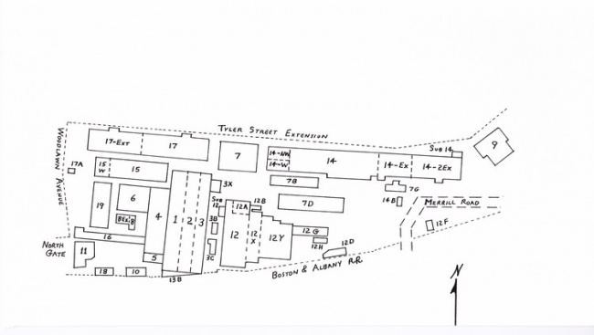
Buildings in Pittsfield Plant (circa 1953)
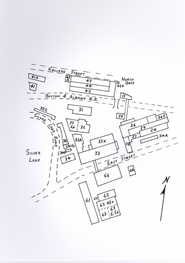
Buildings in Pittsfield Plant (circa 1953) (cont’d)
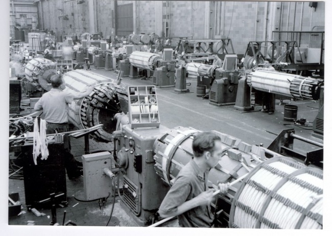
Winding Room (Building 17) in 1950 courtesy of General Electric Company
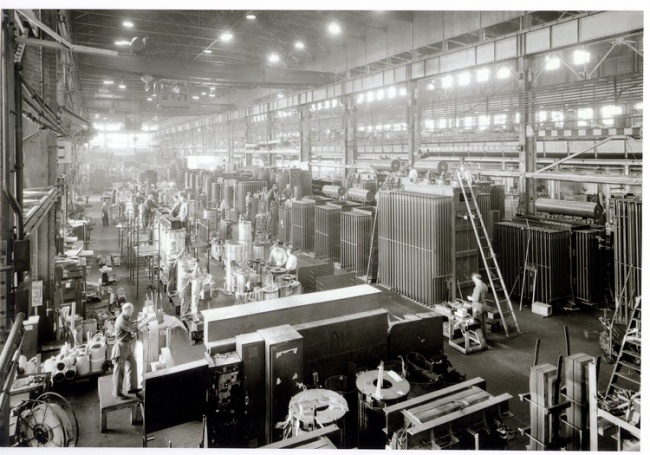
Building 2 from the north in 1952 courtesy of General Electric Company
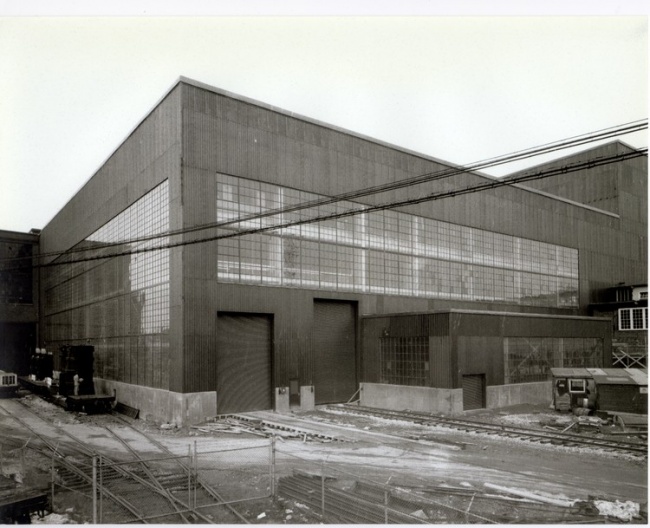
Building 12Y in 1950 (from the southeast) courtesy of General Electric Company
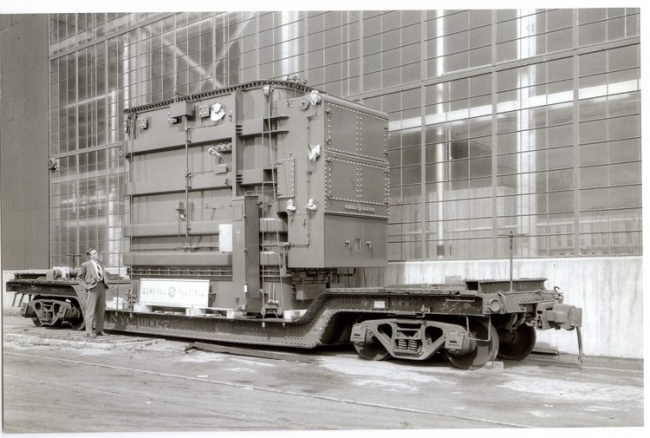
Unit on Drop Frame Car for shipment courtesy of General Electric Company
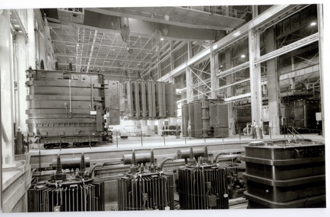
Building 12Y in 1950 with units in Test Pit courtesy of General Electric Company
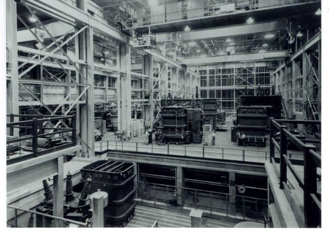
Building 12Y (West Bay) in 1950 courtesy of General Electric Company
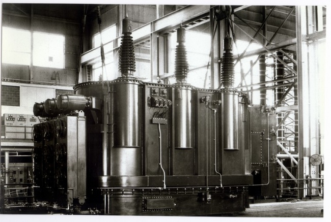
Large unit for TVA in Building 12Y (1952) courtesy of General Electric Company
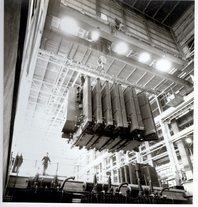
Unit being lifted in Building 12Y (1950) courtesy of General Electric Company
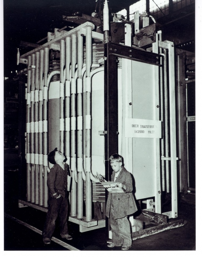
Young visitors at an Open House Berkshire Athenaeum, Pittsfield, MA
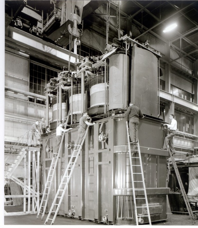
Unit being "tanked" in Building 12Y courtesy of General Electric Company
1954:
- Building 7J was added to the south side of Building 7D. This new addition was for the purpose of housing a 175-ton motor-generator set used to provide power to the test berths in Building 12Y.
- The Stanley Club vacated the mansion which it had occupied on Wendell Avenue in Pittsfield since 1936. The entire club operation moved into the "carriage house" at the rear of the property.
- A new 100-ton crane was installed in Building 3.
- Buildings 7, 8, and 9 were all occupied by various factions of the plant Laboratory.
- A new boiler and smokestack were added to the Power House.
- A nationwide hunt for old transformers which were still in service yielded a Stanley unit dating from 1902!
- Building 12T, an anechoic chamber for audible sound testing of large transformers, was dedicated. This is a poured concrete structure which still stands to the east of Building 12Y. A special railroad track was run between this building and. Building 12Y to transport the transformers via a "donkey" locomotive.
1955:
- Ronald Reagan, then known as the host of the "G.E. Theatre" on television, visited the Pittsfield plant.
- Planning was underway for a new plant to manufacture distribution transformers in Hickory, North Carolina.
- A new Gas Plant which used electrolytic cells to manufacture hydrogen and oxygen went into operation on New York Avenue.
- The fifth Open House was held (previous ones were in 1927, 1946, 1949, and 1953).
- The largest transformer built to date was rated at 300-Mva.
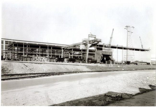
Building 14H under construction in 1954 (from the southwest)courtesy of General Electric Company
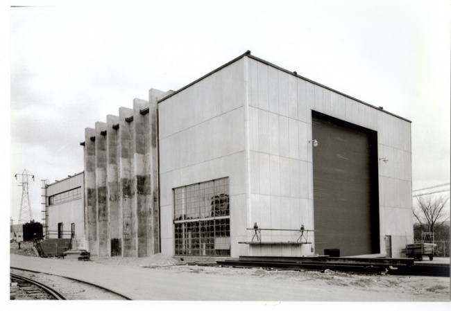
Building 12T from the northwest in 1953 courtesy of General Electric Company

Transformer being moved into Building 12T, Berkshire Athenaeum, Pittsfield, MA
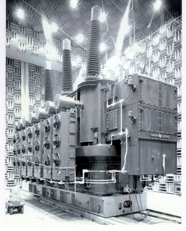
185-Mva unit in Building 12T for Sound Test courtesy of General Electric Company
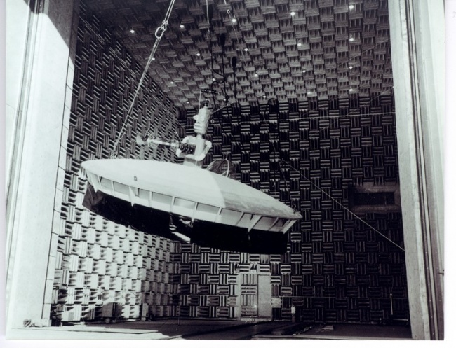
1954 Pittsfield Halloween Parade float (in doorway of Building 12T), Berkshire Athenaeum, Pittsfield, MA
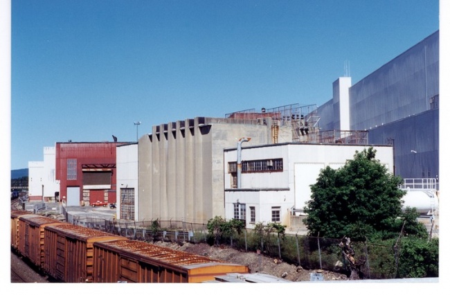
Building 12T from the southeast (in 1996)
1956:
- The G.E. facility on Columbus Avenue in Pittsfield was sold.
- A television commercial was filmed at the High Voltage Laboratory (Building 9) to be aired during the popular "G.E. Theatre" series. The advertisement featured Don Herbert, then known as television's "Mr. Wizard". The feature presentation to be shown was called "Steinmetz" and starred Franchot Tone.
- The largest transformer built to date was for Detroit Edison and was rated at 360-Mva.
- An IBM 705 computer ("the size of a small house") was installed in Building 17. This was the first general purpose computer in the plant (the earlier "Card-Programmed Calculator" was rather specialized), and Pierre Abetti was placed in charge of its operation.
- A new six-operator telephone exchange ("PBX") was installed in Building 16.
- A gas-insulated transformer, designed by Guglielmo Camilli, was built for the Consolidated Edison Company of New York City. Camilli had begun research on such a device in 1937. It was rated at 2-Mva.
- Building 16 had to be evacuated in order to begin necessary repairs to rusted wall truss-units!
1957:
- Building 36 blows up! This was a phenolic resin operation near Silver Lake. A resin pot had been over-pressurized and the resulting explosion destroyed one end of the building, throwing chunks of debris into Silver Lake. Molten resin was spewed over everyone and everything! Two people were killed outright and a third died later of injuries. Two years later, in response to a letter, the Pittsfield G.E. News claimed that the actual cause of the disaster had never been determined.
- A second gas-insulated transformer was sold to Consolidated Edison, and a third one to Pennsylvania Power & Light in Allentown, Pa.
- A new safety slogan was placed on the overhead conveyor between Buildings 26 and 33 on the South Side. It said "Accidents Happen Fast - Think First, Not Last" and it remained until the conveyor (and Building 26!) were torn down in the 1980's.
- "The Castle" in nearby Lenox, Mass. opened. This served as housing for young, unmarried G.E. professionals for many years thereafter.
- The plant cafeteria in Building 25 was closed. It was replaced by Canteen vending machines, a source of complaints until the plant closed in 1987!
- Two power failures shut down the plant!
The first shut down the entire plant for about an hour. It was caused by a short circuit in a circuit breaker located in Building 32S near the Power House. This was the first plant-wide power failure in the fifty-four year history of G.E. operation. In addition, there was a 12-hour delay in restoring power to the South Side which resulted in a lost work day for one thousand workers.
Two days later a second plant-wide power failure occurred! This was due to a cable failure, again in Building 32S. It was most likely somehow related to the event two days earlier. This time, however, the consequences were much more severe. This breakdown placed a short-circuit on one of the transformers at the Silver Lake Substation which tied the plant power system to that of the Western Massachusetts Electric Company.
The transformer burst into flames and, for whatever reasons, circuit breakers tripped as far away as Greenfield, Mass. to the east and North Greenbush, NY to the west! As a result, 85,000 residents in Berkshire County were without power for about twenty minutes, and service was disrupted as far away as Savoy and Sandisfield, Mass. At the Pittsfield plant, one thousand workers were off the job for five days while the necessary repairs were made.
1958:
- It was decided that the plant whistle would no longer be used to signal shift changes.
- A new gate house was built at North Gate, the main entrance to the plant. This structure was torn down in 1981 when turnstiles were installed (activated by I.D. cards).
- The G.E. Credit Union moved into the space recently vacated by the elimination of the plant cafeteria (Building 25).
- The Atmoseal (G.E. trademark) system of oil preservation in large transformers was introduced.
- A pioneering nuclear generating station at Dresden, New York went into operation using two Pittsfield-built G.E. transformers.
- A 25-Mva transformer was built for use at the Doreen Street substation in Pittsfield.
- An announcement was made of the construction of Project EHV, an elaborate research and development facility, in nearby Lenox, Mass. "EHV" stood for "extra high voltage".
- The largest transformer built to date was for Commonwealth Edison (Chicago area) and was rated at 375-Mva.
- G.E. announced that it intended to reinvest forty-seven million dollars in the Pittsfield plant.
- A no-strike vote is taken by the local labor unions.
- Building 10, of 1902 vintage, is torn down.
- The G.E. Meter Department in Somersworth, New Hampshire is added to the Transformer Division of the company.
- An article by Harry Mason in the Pittsfield G.E. News listed "new transformer features": Atmoseal oil preservation system, double-walled tanks for noise reduction, reduced insulation (cost savings), computer-aided designs, high voltage load tap changer, gas-insulated transformer
1959:
- The Jimmy Dorsey Orchestra played at the Stanley Club!
- A 1907 vintage Stanley-G.I. two-phase crane motor was retired in Building 2.
- The largest all-aluminum transformer in the world was built for ALCOA in Massena, NY. It was rated at 20-Mva, had an aluminum tank, and utilized an aluminum sheet winding made of sixty-inch wide foil.
- The local IUE labor union voted a two-week strike.
- The physically largest transformer built to date was a 208-Mva, 417-ton phase-shifter for the Consolidated Edison Company; it was installed in Brooklyn, New York.
- The Project EHV "North Station" on East New Lenox Road near Pittsfield was begun.
- An explosion and subsequent fire occurred outside of Buildings 12A and 12B during short circuit development tests on a voltage regulator unit.
1960:
- A 400-Mva transformer was ordered by the Public Service Electric & Gas Company of New Jersey.
- A pellet-type lightning arrester for home, use was developed in Pittsfield.
- The largest porcelain bushing ever built was for use at Project EHV. It measured twenty-eight feet in height.
- A 115-ton air core reactor was built for use with an Atomic Energy Commission proton accelerator at Princeton, New Jersey. The IUE voted a twenty day strike.
- Project EHV was energized at 720-kv, or 720,000 volts.
1961:
- Westinghouse announced construction of a new plant in Muncie, Indiana for the manufacture of large power transformers, like those G.E. builds in Pittsfield.
- A price-fixing scandal led to seven out of forty-four power industry executives who had been indicted for violation of the Sherman Antitrust Act being sentenced to prison terms!
Some Pittsfield G.E. executives were caught up in this action because it involved the fixing of prices for transformer products.
The seven jailed officials also paid fines totaling $137,500, and the remaining indicted officials paid fines which totaled $1,924,000. In addition, subsequent civil suits resulting from the admission of price-fixing by the companies involved ran into many millions of dollars.
William S. Ginn, former General Manager of the G.E. Power Transformer business in Pittsfield, was one of the officials sentenced to a jail term. Also, Robert Paxton, who had been the top Pittsfield G.E. executive just after World War II, testified that he had known of price-fixing situations as early as the 1930's! This was in hearings before Senator Estes Kefauver's antitrust subcommittee.
Kefauver attempted, without success, to get Ralph J. Cordiner, then the chief executive of General Electric, to admit his knowledge of the conspiracy, and that this was an accepted way of life at G.E. Eventually, Cordiner did admit publically that unidentified G.E. officials had been involved in such activities and had been disciplined and demoted because they had violated G.E.'s own policy on such matters, Policy "20.5".
As an interesting aside to all of this, in the early 1970's, the son of a Pitts- field G.E. executive "defected" and joined the Westinghouse Company after graduating from college. His father-was obligated to submit a formal declaration of having had contact with a representative of a competitor every time his son visited home!
- On a brighter note, Project EHV was now operating at 770-kv, its "South Station" was under construction, and a Family Day was held to show off the project.
It had been intended originally, that the five-mile long high voltage transmission line which was a part of Project EHV would be used to actually transmit power from one end to the other. For various reasons, this was never accomplished. However, to this end, a transformer had been installed at the South Station located near Lenoxdale, Mass. Due to the size of this unit, it could not be transported via highway from the Pittsfield plant where it was built because a bridge on the route would not stand up to the weight. Thus, the transformer had to be taken down a two mile long dirt logging road through the adjacent woods! This required tree-cutting, bulldozing, gravel-hauling, and rock ledge removal along the way. However, the move was completed without any mishaps.
Near the North Station of the project, a three-million volt impulse generator was installed in a large fabric "bubble", which was held up by air pressure from a blower. Occasionally, when impulse tests were being conducted during damp weather, a misfire of the generator would cause a flashover to the fabric bubble. This, in turn, would cause a large tear in the fabric and the bubble would then proceed to deflate and collapse! Ted Brownlee, an engineer from the Pittsfield High Voltage Laboratory, was in charge of the impulse generator operation.
1962:
- The first Open House since 1955 was held.
- Two 607-Mva transformers were built for the East River Generating Station of Consolidated Edison in Manhattan, New York City.
- The Allis-Chalmers Company closed their transformer plant in Terre Haute, Indiana. However, they continued to build transformers at plants in Pittsburgh, Pa. and West Allis, Wisconsin.
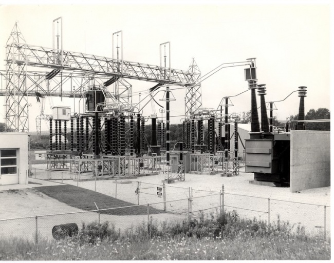
North Station of Project EHV courtesy of General Electric Company
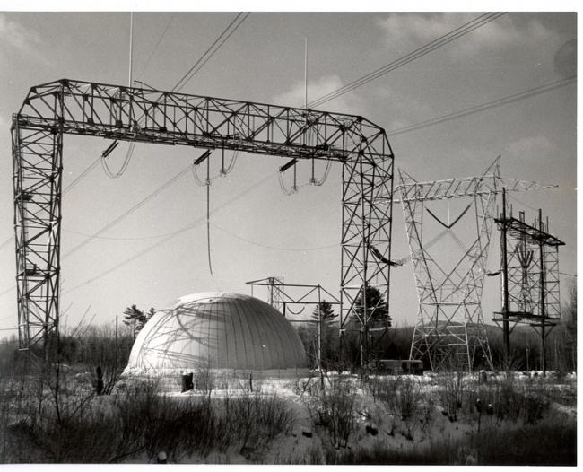
The “Bubble” at Project EHV courtesy of General Electric Company
1963:
- Five 430-Mva, 345-kv, three-phase units were shipped to Arizona Public Service. Two of these were for use at the gigantic generating station located at "Four Corners", the intersection of the boundaries of Arizona, Utah, New Mexico, and Colorado.
- A new corona detection system for detecting partial breakdowns in transformer insulation during high voltage "induce" tests was put into service. This system involved the use of "capacitance taps" available on the transformer bushings to derive a signal which was then displayed via a Radio Noise Meter. Bill Hopf, of Transformer Test, was instrumental in the development of this new procedure.
- For reasons unknown, an empty railroad flat car with a large sign bearing the name and logo of the Westinghouse Corporation was left parked on a siding near the Woodlawn Avenue bridge in the Pittsfield plant for over a week! John Church, of Transformer Engineering, finally removed the sign himself.
- Two 677-Mva, 345-kv units were ordered by the Commonwealth Edison Company. A replica of the original Stanley transformer was built by Larry Fairfield, of the plant's Model Shop, for the Smithsonian Institution in Washington, D.C.
- Project EHV was busy with insulation tests for a proposed 700-kv transmission line by Hydro-Quebec of Canada.
1964:
- A lightning arrester rated at 678-kv was tested at the High Voltage Laboratory (in Building 9) for the Hydro-Quebec transmission line project.
- A worker was fatally crushed in Building 14, the Tank Shop.
- A new type of impulse test, known as the "switching surge" test, was introduced in order to demonstrate the ability of transformer insulation to withstand high voltage surges caused by switching operations on extra high voltage transmission systems.
- Two transformers on a multi-unit order for the Public Power Corporation of Greece ended up under fifty feet of water in New York harbor! These were 40-Mva, 161-kv units. Somehow, a barge carrying them overturned while approaching a ship for loading. Even though it was determined that the tanks had not leaked, after having been lifted from the river bottom they were still returned to Pittsfield for a complete inspection.
- The Consolidated Edison Company of New. York City asked both General Electric and Westinghouse for a completely new design of a gas-insulated transformer. One intended location for such a unit would be the new World Trade Center in Manhattan.
- A new oil storage "Tank Farm" was built between the railroad tracks and East Street in the Pittsfield plant.
- The Pensioners' Orchestra played at a picnic for the Quarter Century Club at the G.E.A.A.
- An 800-Mva, 345/230-kv auto-transformer was built for use at Niagara Falls by the New York State Power Authority. This unit weighed 491 tons installed, and was the largest such unit in the world at the time. It was put in service at the Robert Moses Plant of the NYSPA system.
- The largest generator step-up transformers in the world were the 677-Mva units built in Pittsfield for Commonwealth Edison (ordered in 1963).
- A new computer, a G.E. "415", was installed in Building 17.
1965:
- A response to a letter in the Pittsfield G.E. News confirmed that an engineer had been electrocuted in the High Voltage Laboratory in 1955!
- Three overhead cranes in the plant had been converted to radio-control.
- A portrait of William Stanley, painted by local artist Irving Sisson, was presented to the William Stanley Library by the Stanley Club.
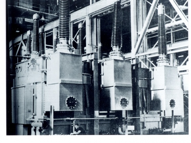
World's largest auto-transformer for NYSPA, Pittsfield G.E. News, Sept. 25, 1964
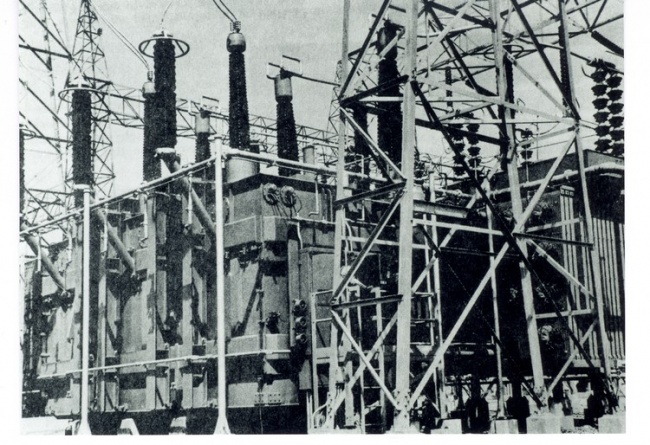
Above transformer installed at Niagara Falls, Pittsfield G.E. News, March 4, 1966
- The vacuum bottle type of switching mechanism for load tap-changing in transformers was introduced. This did away with the use of contacts under oil to break the load current.
- The High Voltage Laboratory constructed a portable impulse generator for field testing of insulation structures. G.G. ("Pete") Kemp and Hans Morf of the Laboratory were instrumental in its design and operation.
- The seventh Pittsfield plant Open House was held. Previous ones were in 1927, 1946, 1949, 1953, 1955, and 1962.
- Announcement was made of the construction of a new Building 11, near North Gate. This was to become a Materials Laboratory. The old Building l1 on the same site was razed.
- Building 34 on East Street received a new facade and other modernizations.
- Announcement was made of the planned con-struction of Building 100, a mammoth new transformer assembly and test building.
1966:
- Seven transformers rated for 500-kv operation were under construction in Building 12Y. The first 500-kv units had been built in 1965.
- The High Voltage Laboratory's portable impulse generator was in use at Leadville, Colorado for high altitude impulse tests.
- The High Voltage Laboratory was named as one of twelve G.E. Research Centers around the country.
- Building 7D, the Woodworking Shop, was razed to make way for Building 100.
- One of two large Pyranol storage tanks was removed from beneath razed Building 12G, east of Building 12Y.
- Williams College, in Williamstown, Mass. near Pittsfield, retired as undefeated champions on the popular television quiz show, "G.E. College Bowl".
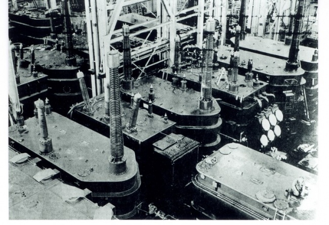
Seven 500-kv transformers in Building 12Y, Pittsfield G.E. News, Jan. 28, 1966
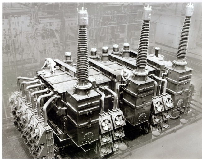
A large three-phase transformer in Building 12Y courtesy of General Electric Company
- A large addition is planned for the Wire Mill, Building 66, which is located south of East Street.
- Merrill Road is closed to vehicular traffic due to Building 100 construction work.
- Building 10, a new short-circuit testing facility, is constructed south of the High Voltage Laboratory and Building 9B.
- A new oil separator facility, to clean oil from ground water, was built south of East Street.
- Power Transformer General Manager Robert Gibson retired to teach at Berkshire Community College in Pittsfield; he is replaced by Ron MacArthur.
- Now the world's largest generator step-up is a 784-Mva, 438 ton unit for the Niagara Mohawk Power Corporation's Nine Mile Point nuclear plant at Oswego, New York. It was built and tested in Building 12Y.
- An article in the Pittsfield G.E. News is about Joe Meehan, who is retiring from the Plant Transportation Operation. He recalls having used a horse and wagon to pick up the payroll at the First Agricultural National Bank in Pittsfield. This was done in the winter when the normally-used electric truck could not make the trip due to snow. The horses were finally retired in 1923. Prior to that, a total of nine horses were kept for hauling materials wagons about the plant.
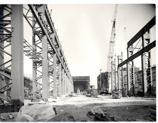
Building 100 construction, looking east courtesy of Mrs. Thomas Nary, Pittsfield, MA
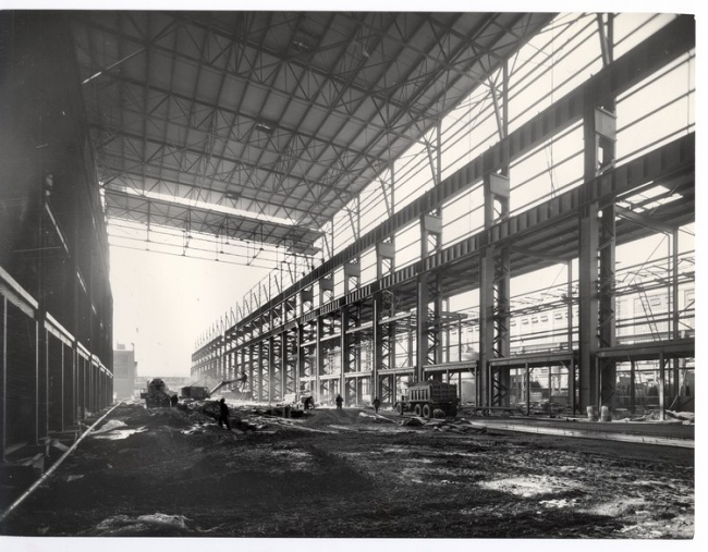
Building 100 construction, looking west courtesy of Mrs. Thomas Nary, Pittsfield, MA
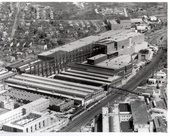
Aerial view from southwest (1967) courtesy of Mrs. Thomas Nary, Pittsfield, MA
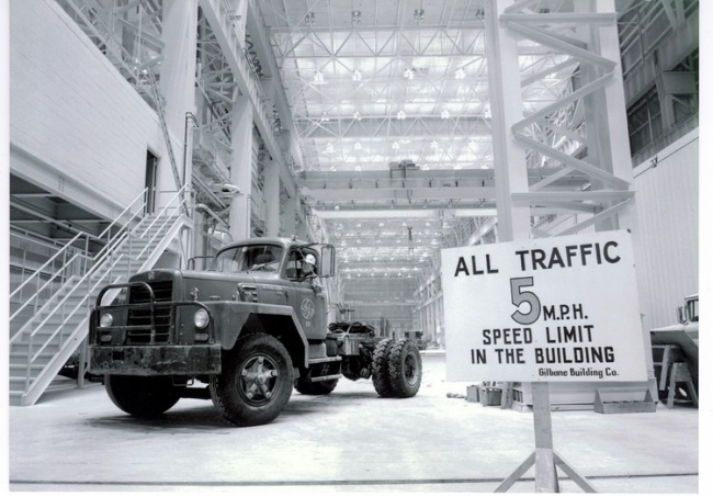
Building 100 construction ("traffic control") courtesy of General Electric Company
1967:
- O.P. McCarty, of Power Transformer Engineering, obtained a patent on the use of the vacuum bottle interrupter in load tap changers. The concept is called "Load-Vac" (G.E. trademark).
- A new building, Building 68, was constructed south of East Street for the mixing of Pyranol. This replaced Building 12G which was razed to make way for Building 100.
- American Electric Power, a giant Midwest utility, ordered transformers for the largest auto-transformer bank in the world. It was to be rated at 1500-Mva, 765/345-kv.
- A two page article in the Pittsfield G.E. News was devoted to the traffic problem around the plant.
- A new plant for the manufacture of distribution transformers was built in Shreveport, Louisiana.
- A short-circuit test facility for lightning arresters was in operation in Building 10, using a special 150-Mva motor-generator set. This facility replaced the former test area in Building 12B.
- Building 7 was torn down. Built in 1907, it had been the site of development work on both silicon steel and Pyranol. It had also been used for laboratory work in the areas of high voltage and metallurgy.
- Peck's Bridge, on Merrill Road, which had been closed due to construction work on Building 100 was re-opened.
- The William Stanley Library moved to a new home in Building 11.
- The first of two 350-ton overhead cranes for Building 100 was delivered by railroad.
- A new Dispensary opened in Building 11.
- The world's largest generator step-up was delivered to Pennsylvania Power & Light. It was rated at 810-Mva, 230-kv.
- Then, the above unit was eclipsed by one for Commonwealth Edison's Dresden II nuclear plant. It was rated at 952-Mva.
- The first of sixty-four DC convertor transformers for the West Coast DC Intertie was shipped to, the Celilo I Substation. It was rated at 107.8-Mva, 235-kv (AC), and had been successfully tested at 600-kv DC for two hours.
- A new 110-ton diesel locomotive was received for use in the plant.
- The Stanley Club was closed temporarily due to a case of food poisoning!
- The new Building 11 was dedicated.
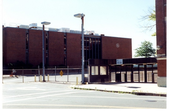
Building 11 (and North Gate) in 1996 photo by author
1968:
- Another new boiler and smokestack were installed at the Power House (Building 31).
- The Stanley Club was completely renovated.
- A new GE-400 computer was placed in operation in Building 17.
- The High Voltage Laboratory placed into operation a new outdoor test facility which was known as Area 72. It was located east of New York Avenue (to the east of the plant) and contained a five million volt impulse generator.
- Building 100 was dedicated.
The first transformer completely built and tested in Building 100 was a 672-Mva generator step-up for Detroit Edison.
A prime consideration in Building 100 was cleanliness, for the sake of the transformer windings. Any dirt blown into the windings could lead to a failure when the transformer was tested.
Thus, to keep dirt out of the building, no windows were included in its design, and the overhead doors were kept closed as much as was possible (although this was very difficult to enforce during hot, muggy summer days!).
In addition, there were sixteen filter and fan units on the roof of the building. These were normally arranged to pull air into the building rather than to exhaust air out. This was done so as to maintain a slight positive air pressure within the building. Thus, when a door did have to be opened, any dirt in the air would tend to blow out rather than in.
Finally, as a further aid to cleanliness of windings, all untanked units were kept wrapped in plastic sheeting in so far as was possible.
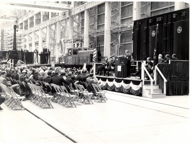
Building 100 dedication ceremony courtesy of Mrs. Thomas Nary, Pittsfield, MA
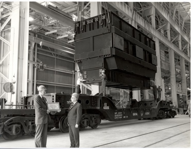
First transformer built and tested in Building 100 courtesy of Mrs. Thomas Nary, Pittsfield, MA
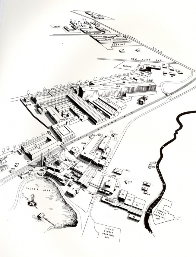
The Pittsfield plant in 1968 courtsey of General Electric Company
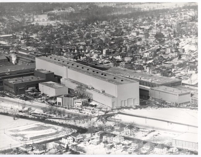
Building 100 from the southeast courtesy of Mts. Thomas Nary, Pittsfield, MA
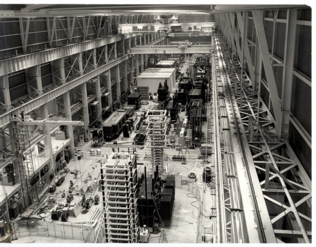
Building 100 interior (looking west) courtesy of General Electric Company
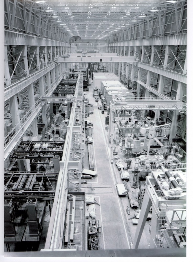
Building 100 interior (looking east) courtesy of General Electric Company
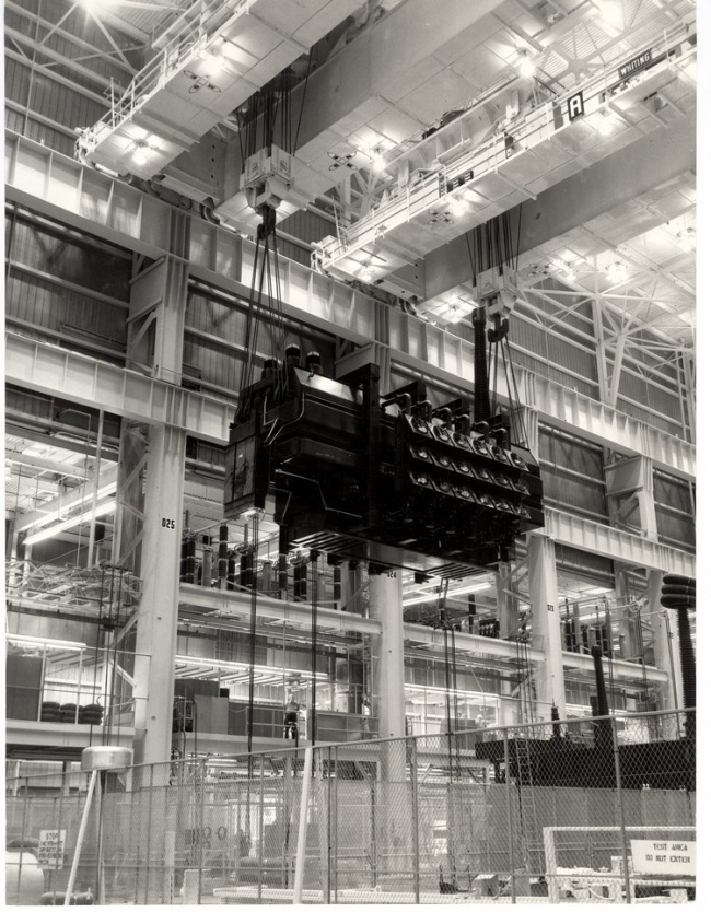
A "two-crane lift" in Building 100 courtesy of Mrs. Thomas Nary, Pittsfield, MA
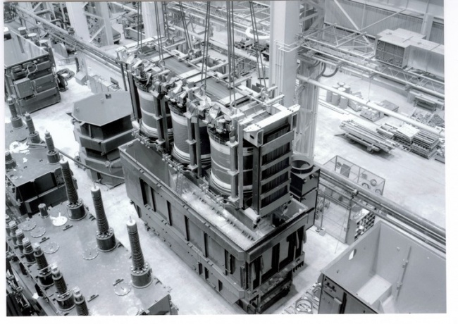
A core and coils being tanked in Building 100 courtesy of General Electric Company
Vacuum Treat
Elaborate precautions were taken to insure that the paper insulation used in the transformer windings was as free of moisture as possible, so as to retain its maximum insulating capability. This was the function of the vacuum treat cycle.
The core and coils were placed in one of several large steel vacuum tanks. The covers of these tanks were hinged, and were lifted by means of a steel cable and winch system. High pressure steam coils around the inside walls of the tank heated the interior while a vacuum was being pulled. This combination of heat and vacuum served to pull moisture out of the insulation.
In addition, a quantity of a kerosene-like liquid (called "vapor-phase") was placed in the bottom of the tank during this process. The evaporation of this liquid helped to further raise the temperature of the core and coils. Thermocouples placed within the windings allowed for a determination of the dryness of the insulation according to how the heat was penetrating the windings. This took several days for large transformer core and coil units.
The vacuum pulled within the tank was measured in microns (millionths of a meter). This measure of vacuum is based on the fact that normal atmospheric pressure will support a column of mercury 760 millimeters high. Thus, normal atmospheric pressure equals 760 millimeters. Since one micron equals 1/1000 of a millimeter, the vacuum attained during treat was very high indeed!
When sufficient dryness was indicated by the thermocouples, vacuum was broken by introducing oil into the bottom of the tank. Oil was admitted until the core and coils were completely covered, and then the unit was allowed to soak for a prescribed number of hours before being lifted out. The core and coils were then allowed to drip while suspended by crane over the open vacuum tank. Following that, the unit was placed in a "dry room" nearby. While in the dry room, "space and adjust" procedures were carried out to be sure that the coils were still properly clamped in position following vacuum treat.
The core and coils were then lifted out of the dry room and placed in the steel transformer tank. Following the making of final connections (to tap changers, etc.), the cover was welded on and a vacuum was pulled on the tanked unit to again pull any residual moisture out of the insulation. This "secondary treat" process was often called "being on one mil" because the vacuum attained was equivalent to one millimeter of mercury, or 1/760 of standard atmospheric pressure. During the process, the moisture removed from the windings was frozen by means of a "cold trap". Periodic weighing of the frozen moisture was an indication of how the drying process was progressing. When sufficient dryness was achieved, the unit was filled with oil. It was again allowed to soak for a prescribed time and was then sent to Test.
Following Test (assuming it passed all tests successfully!), the unit was drained and prepared for shipment. Nitrogen gas at low pressure was introduced as the oil was drained to prevent moisture-laden air from re-entering during shipment. A nitrogen gas bottle and regulator were attached to the unit during the entire trip to its destination.
There was a "legend" passed down through the years at the Pittsfield plant concerning thieves who had been killed by suffocation because they had removed a manhole cover from a transformer tank during shipment in order to enter it and steal copper. There would have been, of course, no air in the tank!
If a problem was discovered inside of a transformer during Test, all attempts were made to correct the problem without draining the oil. If the unit had to be drained, it would have to be put through the very time-consuming process of vacuum treat all over again!
Don West, a Factory. Contact Engineer, became very adept over the years at accomplishing "miracle" fixes in oil-filled transformers. Sometimes, he had to perform the task at hand by stripping naked and climbing into the oil through a manhole. This would be done on the third shift, when very few people were around!
The cartoon on the following page was drawn years ago by "Tex" Allen of Manufacturing Engineering. It was used as a Managerial Award to Don for one of his more cost-saving "skinny-dips". According to Don, it is accurate except for the boxer shorts added by Tex!
Actually, this type of activity was not to be taken lightly. Mineral oil will coat the lungs of anyone who is unfortunate enough to accidently swallow a mouthful of it; suffocation would result.
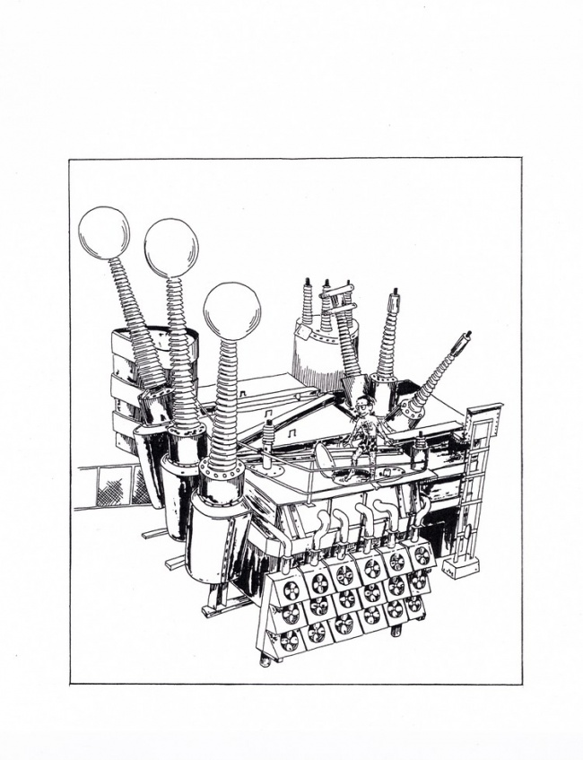
Don West "at work"! (by M.R. "Tex" Allen, courtesy of Don West)
1969:
- A single-phase, 1500-kv transformer was built for Project EHV. This was part of an upgrading in order to study even higher transmission voltages. Thus, the facility was renamed as Project UHV (for "ultra-high voltage").
- Thirty-one railroad transformers were built for the New York City to Washington, D.C. "Metroliner" operated by the Penn-Central Railroad. They were designed to operate on both 25-Hertz (the original railroad frequency) or 60-Hertz (for modernization work).
- The Stanley Club members voted to retain the membership policy of "no women"!
- Letters of complaint were seen in the G.E. News about Building 100: too noisy, too hot, too cold, loud steam pipe banging!
- An article in the Pittsfield G.E. News was devoted to an explanation of the efforts in regards to water pollution control in the Pittsfield plant and surroundings.
- New parking lots were built on Tyler Street Extension.
- An 1898 Stanley transformer was removed from a Building 12 test berth (still working!).
- A strike was called by the UE and IUE locals. A blizzard, dropping thirty-six inches of snow, caused the second plant closing of the year, the only two closings in memory!
- A massive core cradle, designed by Ed Kopf, was in operation at the north end of Building 3. This allowed steel transformer cores weighing up to 250 tons to be built horizontally and then tipped up to the vertical position. A railroad-type car, which originally was in a vertical position, was then used to move the core into adjacent Building 100. The 90-degree tipping operation took twenty minutes for a large core! The forces on the hydraulic tipping mechanism were so great that it was anchored via a foundation which contained over 100 tons of concrete, and steel pilings driven forty feet down to the bedrock beneath!
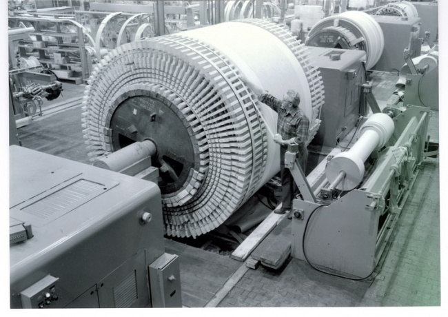
Large coil being wound on lathe in Building 17 courtesy of General. Electric Company
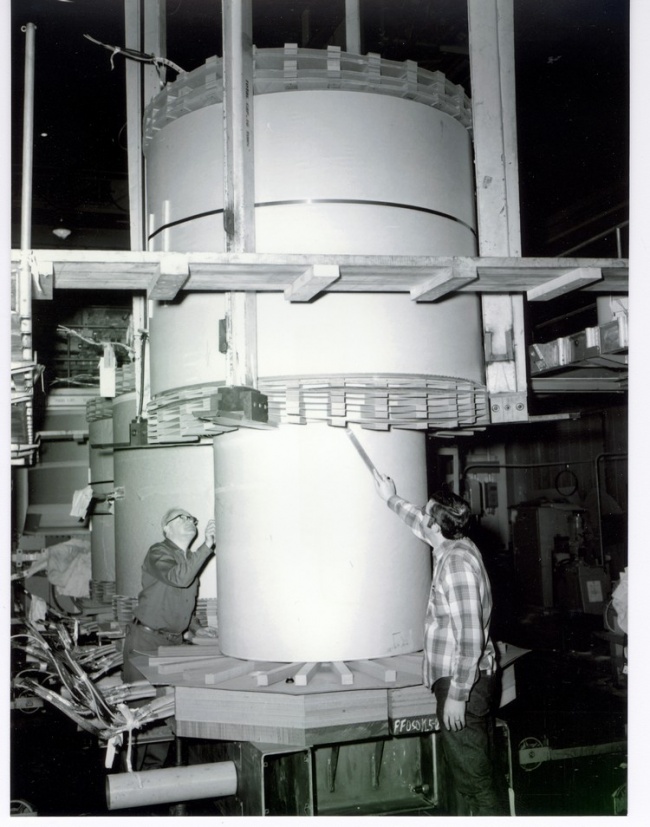
A large coil being "landed" in Building 100 courtesy of General Electric Company
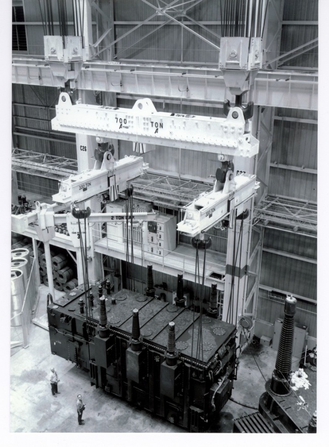
The "spreaders" or "lifting beams" were used when it was desirable to keep the lifting cables vertical in order to take advantage of their maximum lifting capability; also, sometimes their use was necessary in order to avoid bushings with the cables. The upper (700-ton) spreader is held by the hooks from the two 350-ton overhead cranes. The two smaller spreaders are rated at 350-tons each. The hooks in the spreaders were positioned for each particular lift, by means of electric motors in the spreaders themselves. This was done before making the "hitch". The unit being lifted is one-half of a two-tank "phase-shifter". Courtesy of General Electric Company
Chapter 7: Shipping and Installations
The size and weight of large power transformers was always a problem as far as being able to ship them to their final destination was concerned. For the most part, the transformers built at the Pittsfield plant were shipped by railroad.
The engineers who designed these transformers had to take shipping into account at a very early stage of the design process. There was no value to a design if the resulting transformer could not be shipped! One of the most severe limitations faced was the available clearance under the North Street bridge in Pittsfield. By the 1980's, General Electric had been in discussion with Conrail about the possibility of lowering the railroad tracks in the vicinity of this bridge to obtain a bit more clearance. This would have made the job of the transformer designers somewhat easier by allowing the use of slightly higher tanks. Of course, the closing of the Pittsfield plant in 1987 eliminated the need for such considerations!
Occasionally, transformers destined for locations relatively near to Pittsfield were shipped from the plant by truck. The most obvious of this type of situation was in regard to transformers needed over the years at the Silver Lake Substation located next to the plant in Pittsfield. These were not terribly huge in weight or in dimensions, but it still required some careful planning just to move these units from their place of assembly in the plant "around the corner" to Silver Lake!
During the early years of operation at the Pittsfield plant, transformers were still small enough to be shipped on conventional railroad flat cars. If weight was still a problem, they would be shipped without oil inside. The oil would then be added after the transformer had been positioned at its destination. In later• years, this procedure became standard of necessity.
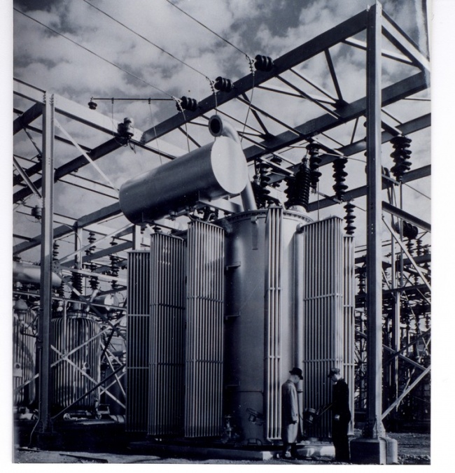
Transformer at Silver Lake Substation (15-Mva, 114/23 kv) courtesy of General Electric Company
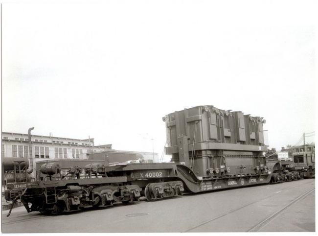
Large transformer on drop frame car courtesy of General Electric Company
Eventually, the railroads themselves designed what were known as "drop frame" cars. These cars allowed the bottom of the transformer tank to ride as close as twenty-four inches above the rails. By 1952, however, these cars were no longer able to carry the largest transformers being built; the car capacities allowed a maximum weight of 200 tons. Thus, over the next ten years or so, G.E. purchased four 250-ton, 10-axle drop frame cars themselves.
Also, during the 1960's, G.E. purchased three 312- ton, 12-axle "side rail" cars. These cars allowed a specially designed transformer tank to sit between two side rails, to within only twelve inches of the track rails!
In 1971, a 600-ton, 20-axle "Schnabel" car was purchased. This foreign-designed car was specially designed for the transportation of heavy transformers. The transformer tank itself actually became the car. Two end units attached to the tank via special pin fittings at the bottom. These end units were equipped with very elaborate hydraulically-operated systems which allowed for the vertical and horizontal shifting of each end of the transformer several inches. This enabled otherwise impassable clearances to be negotiated. The train had to be stopped, however, in order to perform these maneuvers. When in motion, the transformer tank was able to ride only eight inches above the rails!
In later years, a total of four 325-ton, 12-axle Schnabel cars were purchased as well. Also, it had been decided to "derate" the capacity of the 20-axle Schnabel cat to 550 tons. This was merely to allow a factor of safety, not because of any shortcomings in its design.
On its maiden voyage, however, the 20-axle Schnabel car was wrecked! Actually, it successfully delivered a transformer to Florida Power and Light. On the return trip to Pittsfield, the empty car (its two ends coupled. together) was located near the center of a train with a lot of heavy cars behind it. The train had to make a fast stop near Antietam, Maryland, and the Schnabel car was squeezed right off the tracks due to the weight of the train behind it. Part of it had to be returned to the manufacturer in Italy for repairs, and it was out of commission for several months.
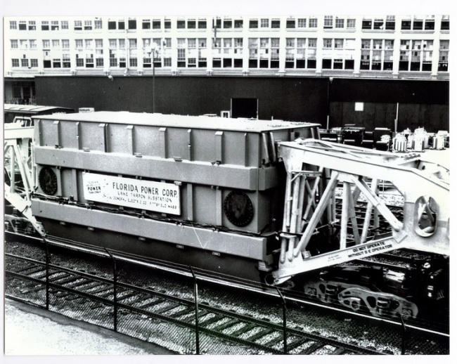
First use of 600-ton Schnabel car courtesy of General Electric Company
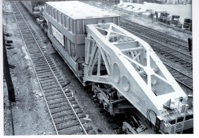
Close-up of one end of Schnabel car courtesy of General Electric Company
During the 1930's, the Pittsfield plant built the transformers for use at Boulder Dam (now Hoover Dam) on the Colorado River between Arizona and Nevada. Also, during the 1940's, transformers for Grand Coulee Dam on the Colombia River in Washington State were built in Pittsfield.
In both cases, a rather novel approach to shipping was used. Special "tank" cars, which consisted of a container and lid combination, were built to ship the core and coils. The transformer tanks were shipped separately. The core and coil units were kept in low pressure nitrogen gas during the trip to keep them dry.
This procedure had as much to do with the difficulty involved in getting the transformers into position at their destinations as with the shipping operation. For example, at Boulder Dam, the only means available for lowering heavy power house equipment to the base of the dam was via a 150-ton cableway stretched between the canyon walls. Also, for this reason, the transformers for both dams were single-phases units rather than three-phase. This meant that each transformer was lighter. Of course, three times as many transformers were needed.
The largest transformers for Boulder Dam were rated at 55-Mva and 287-kv. Each one weighed 220 tons when filled with 22,000 gallons of mineral oil. Without oil, the weight was 135 tons; thus, they were lowered into the canyon empty. Prior to this, the core and coils had been placed into the tank at an assembly area near the canyon.
The Boulder Dam order was placed in 1934, and all transformers were in place by 1936 when the first generator at Boulder Dam went on line. These transformers remained in service until at least 1983, when an extensive uprating project began at the dam. This project lasted until 1992.
A total of seven 55-Mva transformers were shipped from Pittsfield (two three-phase banks plus a spare); in addition, four 13.3-Mva units (one three-phase bank plus a spare) were shipped to Boulder Dam.
The transformers for Grand Coulee Dam, rated at 36-Mva each, were shipped in 1941. In this case, the core and coil units were placed in the tanks inside the power house itself.
Both of these installations represented major advances in the state-of-the-art of transformer design and construction at the time.
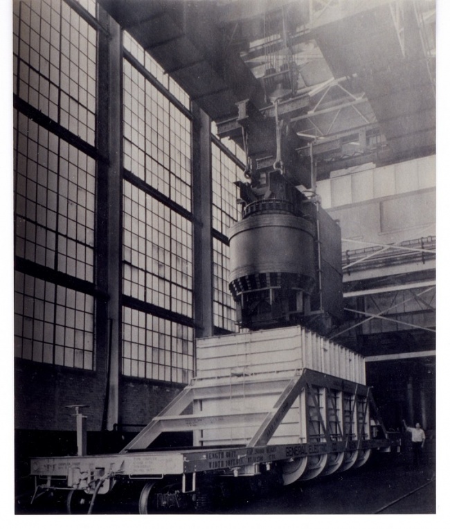
Boulder Dam core and coils being loaded, courtesy of General Electric Company
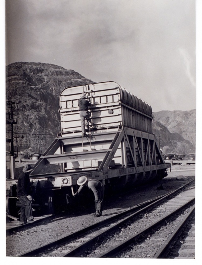
Grand Coulee core and coils at destination courtesy of General Electric Company
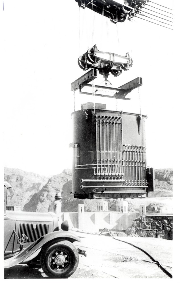
55-Mva Boulder Dam transformer hung on cableway over canyon (Boulder Dam in background) Hall of Electrical History 103
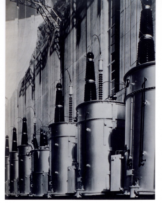
G.E. transformers in service at Boulder Dam (dam and Arizona powerhouse in background) courtesy of General Electric Company
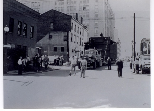
Negotiating the streets of Rochester, New York (1958) courtesy of General Electric Company
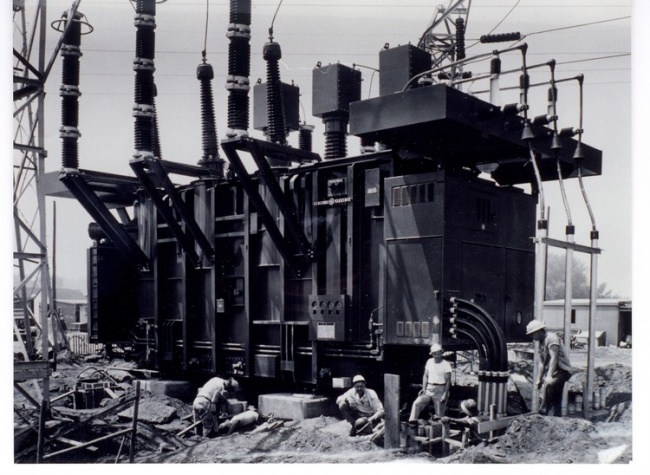
An installation at Dunkirk, New York (1959) courtesy of General Electric Company
Perhaps one of the most difficult transformer deliveries (if not THE most) on record involved an order for HVDC equipment in the late 1970's. The shipment was to Zaire, Africa. This was formerly known as the Congo; now (in 1997) following a revolution, it is once again known as the Congo!
This equipment was for an 1150-mile long HVDC transmission line which was to run from the Inga Dam on the Zaire (formerly Congo) River to a large copper mining area in the Shaba region, near Kolwezi. The primary purpose of this project was to supply electric power for the mining of copper.
This was a twenty-three million dollar contract which called for the supply of thirty-two DC convertor transformers, twenty-nine smoothing reactors, and other miscellaneous types of equipment. The contract details were handled by Werner Heidemann, then Manager of HVDC Sales in Pittsfield.
The shipping of this equipment presented even more difficulties than were usually encountered with the shipment of large power transformers. The units were shipped by ocean-going freighter to the port of Matadi, just up the Zaire River from the west coast of Africa. At Matadi, they had to be transferred to specially-built Schnabel cars to avoid, a series of impassable rapids in the river. Two hundred miles upstream, they were transferred to special river barges equipped with on-board cranes for the next 400 miles. Then, they were put back on Schnabel cars for the 600 mile remainder of the journey!
R. Kelly Niederjohn, then a mechanical engineer in the Power Transformer Department, was intimately involved with the shipment of these transformers. In 1975, he spent sixteen days in Zaire as part of a railroad evaluation project team to determine what problems existed, with the rail portion of the journey. A plywood template which defined the outline of the largest units to be transported was run along the rail route to find and correct clearance problems.
Five special 24-wheel railroad cars were built for this venture by the Maxson Corporation of St. Paul, Minnesota: two depressed-center (drop frame) cars and three Schnabel cars. Special river barges were built by Lunde, Inc. of San Francisco. Prior to this, the maximum load which could be transported across Zaire was thirty tons. The special equipment provided for this project more than tripled this limit.
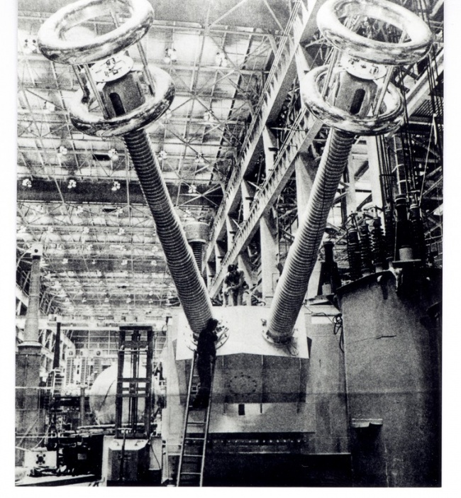
HVDC convertor transformer for Zaire, Africa (57-Mva, 500-kv) Pittsfield G.E. News, Feb. 28, 1975
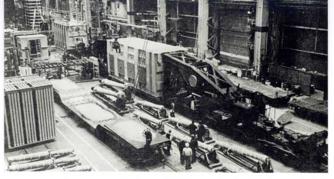
Unit for Con Ed on Schnabel car in Building 100, Pittsfield G.E. News, Jan. 13, 1978
During 1979 and 1980, three huge transformers were built for the Southern California Edison Company. These were three-phase generator step-ups and were probably the heaviest loads (of any type) ever to be shipped by rail across the country.
These units were christened the "Big Boys". They were installed at the San Onofre Nuclear Generating Station, about eighty miles from Los Angeles and near Camp Pendleton. The transformer designer was Al Rowe. Each unit was rated at 1378-Mva, stepping up from a generator voltage of 21.4-kv to a transmission voltage of 230-kv.
When filled with oil, each weighed 597.5 tons, this being a calculated weight since there was no equipment in Pittsfield to actually weigh such heavy transformers! They were, of course, shipped without oil in them. The combined weight of one of these units (empty) and the 20-axle Schnabel car which carried it was 650 tons. The cores of these transformers each weighed 254.5 tons by themselves. These cores were built in the Building 12 complex, and a Schnabel car had to be used just to move the cores from there up to Building 100 for the assembly of the transformers! This was accomplished by moving the cores out onto the main line of the railroad which is adjacent to the Pittsfield plant and then back into the plant again.
R. Kelly Niederjohn, by then retired from Power Transformer Engineering, was hired to accompany each of the three transformers on its two week trip to its destination because of his familiarity with the use of the Schnabel car. He made sure that the train's braking system was double-checked before proceeding down any major hills during the journey!
When the first unit arrived at San Onofre, the rigger there found that he was unable to lift it! By using a weighing method involving strain gauges, he determined that it weighed 515 tons. The calculated weight from Pittsfield, however, was significantly less than 500 tons. Thus, he had to revise his rigging set-up to be able to lift the unit.
As far as this being the heaviest coast-to-coast shipment ever, a Schnabel car larger than the one used to haul the Big Boys does exist. It is believed that it has 32 or 36 axles, and is owned by Combustion Engineering. It is used to move such mammoth loads as nuclear reactors. However, it is not believed that it has ever been used for such a long distance move as this one.
Chapter 8: Towards the End
Conservation measures resulting from the Arabian Oil Embargo of the late 1970's caused a reduction in the use of electricity in this country. This led to severe cutbacks in expansion plans of the U.S. electric utilities.
That, in turn, had devastating effects on the market for large power transformers which were the "bread and butter" of the Pittsfield G.E. operation. In 1982, according to Nicholas Boraski, G.E. Vice-President and General Manager of the Pittsfield Large Transformer Business Division at the time, "the market for our products is fifty percent below, what we had in the days before the Oil Embargo".
Boraski called for a twenty-five percent improvement in productivity and said that, if the market did not improve, five hundred fewer employees would be needed by the end of 1983. Accordingly, a "Make It in Pittsfield" campaign was instituted as a means to try to save the Pittsfield transformer business.
In February of 1983, sixteen hundred employees attended sessions of a presentation conducted by Boraski and Tom Wise, Manager of Engineering and Manufacturing for LTBD. Wise stated that the biggest problem faced was "the total cost to produce a transformer and to run the business". He indicated that the Westinghouse Corporation, traditionally G.E.'s major competitor in the transformer business, was facing the same situation.
In 1984, Wise announced that the "Make It in Pittsfield" program was to be expanded mainly due to:
- a basically non-growth market for large power transformers
- a severe over-capacity situation for the electric utilities
- fierce international competition for power transformers
He indicated that three options were available for the Pittsfield operation: "Fix it, Sell it, or Close it"!!
Unfortunately, the market situation did not improve, and, by 1986, the third option was the only one left.
However, in the meantime:
1970:
- The longest strike in Pittsfield since 1946 ended in January; it had lasted 101 days.
- the largest phase-shifter ever built was a 300-Mva, 138-kv, 500-ton unit for the Long Island Lighting Company ("LILCO").
- A second oil separator was installed south of East Street as part of a six million dollar water pollution control program.
- A universal spare generator step-up transformer was purchased by a Midwest utility. It was to be stored on a railroad car so that it could be moved to any of their generating stations where it might be needed in an emergency. The railroad car was supplied by G.E. as part of the purchase price!
- A 784-Mva, 345-kv generator step-up unit was built for Niagara Mohawk Power Company's Nine Mile Point nuclear plant near Oswego, New York.
- Project UHV built a ten-sided ("decagon") building for the study of transmission line insulator breakdown under contaminated conditions.
- A New York Times article commented on the "dumping" of foreign-built power transformers in the U.S. at artificially low prices in order to steal business from domestic manufacturers such as G.E.
1971:
- Both the G.E. Credit Union and the Employees' Store moved from Building 42 to a new building on Kellogg Street, outside of the North Gate.
- Foreign competitor ASEA, of Sweden, built a 935-Mva generator step-up transformer for Northeast Utility's Millstone, Connecticut nuclear generating station!
- The first shipment of a transformer via the new Schnabel car was made (see Chapter 7).
- General Electric Corporate Headquarters moved from 570 Lexington Avenue in Manhattan to Fairfield, Connecticut.
1972:
- The Western Massachusetts Electric Company installed gas turbine generating units for "peaking" power at the Silver Lake Substation by the plant.
- A new telephone system called Centrex was put into operation in the plant. The main exchange equipment was in Building 29B on East Street (a former Berkshire Gas Company building).
- Three Pittsfield G.E. managers (Tony Gizzi, Deane Haywood, and Dave Herder) died in the crash of a Mohawk Airlines plane at Albany, New York.
- Incentive pay gave way to "day work" rates for hourly workers in the Pittsfield plant.
- A thermal oxidizer which burned chemical pollutants found in groundwater was installed near the Housatonic River, south of East Street.
- General Electric requested a probe by the U.S. Government into the practice of dumping foreign-built transformers in this country.
- "The Castle", longtime living quarters for G.E. bachelors, closed in Lenox.
- Neighbors of the High Voltage Laboratory's outdoor test area, off New York Avenue, were invited for a tour of the facility.
1973:
- Les Jump, an engineer who re-located to Pittsfield from the AEI Company of Manchester. in England, warned of the very real possibility of a plant closing here because he had seen it happen there!
- A Family Day was held in the plant in April.
- O'Brien's Woodlawn Cafe, and an adjoining house, on Woodlawn Avenue were razed to make way for a new parking lot.
- This year marked the sixtieth anniversary of the Pittsfield G.E. News.
- Competitor Central Moloney of St. Louis, Missouri went out of the power transformer business.
- ASEA of Sweden won a large order from the Commonwealth Edison Company, of Chicago, beating out General Electric, Westinghouse, and the McGraw-Edison Company. This was for seven single-phase generator step-up transformers.
- The New England Power Company's Bear Swamp pumped storage hydroelectric, generating facility on the Deerfield River (in the towns of Florida and Rowe, Mass.) was soon to go "on-line". This plant used two generator step-up transformers from Pittsfield with their two 300-Megawatt generators.
1974:
- The former Brass Rail Tavern at the corner of Woodlawn Avenue and Kellogg Street, just outside of the North Gate, was now the site of a new building housing the G.E. Employment and Personnel Office. Formerly, this had been located in Building 42.
- A second 1500-kv, single-phase transformer was built for Project UHV. The first had been built in 1970, and a third was to be built.
- It was announced that the 1903 railroad bridge within the plant was to be replaced.
- A 400-Mva auto-transformer was moved from a New England Power Company substation in Ludlow, Mass. to the new Berkshire Substation located on George Schnopp Road in nearby Hinsdale, Mass. This was done in order to tie the 345-kv system of New England Power to the 115-kv transmission lines between there and the Doreen Street Substation in Pittsfield. The transformer had been built in Pittsfield in 1972.
- Four 672-Mva, 230-kv phase-shifters were built for Public Service Electric and Gas of New Jersey. These were to be used for a system tie with the Philadelphia Electric Company in Pennsylvania.
- The first of twenty-six HVDC convertor transformers was built for the Square Butte project, a 450-mile HVDC line running from North Dakota to Minnesota.
The first HVDC line in the country Was the West Coast Intertie, running from Portland, Oregon to Los Angeles. This was built between 1965 and 1970, and used mercury arc rectifiers to convert between AC and DC.
The first HVDC intertie using solid-state rectifier devices was the Eel River Project running from New Brunswick to Quebec, Canada, built in 1972.
- Andy Glassanos was chosen to head an HVDC research and development project sponsored by EPRI, the Electric Power Research Institute. This was to involve an HVDC tie at the Astoria Generating Station of the Consolidated Edison Company in New York City.
1975:
- Three new winding lathes(vertical type) were installed in Building 1, plus two of the more conventional horizontal type.
- The G.E. Transformer Division's computers were all centralized in Building 34 on East Street.
- The first convertor transformer was built for the Zaire, Africa HVDC project (see Chapter 7).
1976:
- Competitor Allis-Chalmers of West Allis, Wisconsin announced that they were going out of the power, transformer business. In the future, their designs would be built by Siemens of West Germany.
- The largest transformer ever built was for the Bureau of Reclamation and was for use in Phoenix, Arizona. It weighed 900 tons (two tanks) and was rated at 500-Mva, 230-kv with a +36°/-24° phase shift. It cost two million dollars.
When the first half was shipped, it ended up on its side after a train derailment near Toledo, Ohio! It was returned to Pittsfield and the re-build took six months.
- It was announced that the use of Pyranol would be phased out by April of 1977.
- An East-West HVDC intertie, using Pittsfield built convertor transformers, was placed in operation at Stegall, Nebraska.
- The new Berkshire Substation in nearby Hinsdale was put on-line.
- The highest capacity transformer bank in the world was in operation on the system of the Ohio Power Company (a part of American Electric Power) in Marysville, Ohio.
The bank consisted of four (one spare) units rated at 1000-Mva each, single-phase. They operated between a 765-kv system and a 345- kv system. Each unit had dual 345-kv windings, each winding rated for 500-Mva.
1977:
- The G.E.A.A. picnic shed burned completely to the ground. It would be re-built.
- The Stanley Club was re-decorated.
- The Pittsfield G.E. Naval Ordnance Operation took over Building 34 on East Street. This was an indication of the shrinking presence of the transformer operation. The parking lot in front of Building 34 was expanded for this new usage.
- A really "hot" rush job was the building of a 550-Mva generator step-up transformer for the New England Power Company at Brayton Point (near Fall River, Mass.). This was a replacement for a Westinghouse transformer which had failed in service! This transformer had to be shipped by rail from Pittsfield to Hudson, New York, then by barge down the Hudson River, around the tip of Manhattan Island, and out Long Island Sound to its destination because of railroad right-of-way restrictions between Pittsfield and Fall River. The transformer was, by the way, built in half the normal time required for such a unit!
- Then, two more rush jobs were also generator step-up units, again to replace failed Westinghouse units! These were both for Detroit Edison, and one was for the Fermi II nuclear generating station.
- The 1977 blackout which affected New York City created a rush order for two large phase-shifter units which were to be installed at Consolidated Edison's Farragut Substation in Brooklyn.
- The "Big Boys" were built for Southern California Edison (see Chapter 7).
- Project UHV now had the capability to perform HVDC testing at either ±750-kv or at 1500-kv to ground.
1979:
- John Anderson, Manager of the High Voltage Laboratory, was elected to the National Academy of Engineering.
- A 952-Mva generator step-up from the Dresden nuclear plant of Commonwealth Edison was returned to Pittsfield for repair.
- Commonwealth Edison retired six single-phase General Electric transformers, each rated at 333-Kva, which had been in operation since 1914!
- A new GEORG core-slitting machine was installed in Building 15. This machine produced core steel laminations with very few steel burrs; this led to reduced magnetic losses in the transformers.
- Andy Lyke was placed in charge of a project to develop a gas-insulated transformer design for the Department of Energy. This was to utilize sulfur hexafluoride gas, aluminum foil sheet windings, and a film type of insulation (the modern equivalent of Camilli's work dating from 1937).
- The gate house at North Gate, built in 1912, was torn down (with some difficulty; it was well built!). This was done in order to make way for turnstiles which would use a card-key system for entrance to the plant.
- New parking lots were constructed along the south side of East Street to accommodate G.E. Ordnance employees who would now be working in Buildings 28, 33, and 63. These buildings had been evacuated by the transformer operation.
1980:
- Consolidated Edison ordered a third phase-shifter for the Farragut Substation in New York City (Brooklyn). Also, Public Service
Electric and Gas of New Jersey ordered a 500-Mva, 230-kv phase-shifter.
- An 870-Mva, 500-kv auto-transformer was built for the Jersey Central Power & Light Company.
- A "Clean Room" was built in the east bay of Building 12Y for the gas-insulated transformer project.
- The Card-Key plant security system went into operation.
1981:
- Building 73, a regulator life-test facility, was constructed off of New York Avenue.
- The Silver Lake Barge was dismantled. This had been a facility on Silver Lake, operated by G.E. Ordnance, for the purpose of torpedo sonic testing.
- Nicholas Boraski, General Manager of the Large Transformer Business Division, made the announcement that work force reductions would include lack-of-work notices for some salaried employees.
1982:
- Building 8, built in 1901, received a new roof. At one time, this served as the Main Gate to the plant. At the same time, Building 16, next door, also was re-roofed.
- Two 3000-Kilowatt rectifier transformers were built for the New York City Transit Authority. These were part of a program to modernize the power system which provides 600-volts D.C. to run the subway system in New York City (via third rails).
- Herm Hill, General Electric vice-president, was quoted as saying that the transformer re-vitalization program "can work".
- Andy Glassanos of Power Transformer told a meeting of EPRI (Electric Power Research Institute) that "G.E. is in the power transformer business to stay!"
- G.E. was bidding on an HVDC project for Hydro-Quebec of Canada.
1983:
- Thirty-five rectifier transformers and twenty-four reactors were built for the Tokamak controlled-fusion test reactor at the Princeton University Plasma Physics Laboratory in Princeton, New Jersey. This was an attempt to harness nuclear fusion as an alternative to nuclear fission for the production of electric power.
- Four 56-Mva generator step-up transformers were built for the Egyptian Electric Authority. These were 50-Hertz units, this being the standard power frequency in Egypt.
- Four 500-Mva auto-transformers and four 400-kv series reactors were built for the GURI hydroelectric project on the Caroni River, six hundred miles from Caracas, Venezuela. This was the second largest hydroelectric project in the world, and it cost six billion dollars.
- The largest transformer ever shipped by truck from the Pittsfield plant was for the Blackstone Valley Electric Company in Rhode Island. It was a 300-Mva auto-transformer with a shipping weight of 127 tons. Bill Carter, Jr. was the transformer designer.
- General Electric received the order for HVDC equipment for the Hydro-Quebec intertie with New England. G.E. beat out foreign competitors ASEA and Brown-Boveri, and supplied the transformers and related equipment for the southern terminal of the HVDC transmission line, located near Monroe, New Hampshire. It was to be known as the Comerford Station.
- Power Transformer bought one hundred thousand dollars worth of personal computers for use by Engineering and Drafting personnel.
- The High Voltage Bushing Operation moved into Buildings 3 and 12 from Building 51 on Plastics Avenue. G.E. Ordnance took over the latter building.
- The Quality Circles team-building technique was instituted in the transformer operation.
- Power Transformer invested in a new 320-ton, 12-axle M drop frame railroad car for the shipment of large transformers.
- The Pittsfield plant Materials Laboratory developed a PCB Test Kit for field testing of PCB contamination of electrical equipment.
- "Rusty", a Doberman pinscher owned by Pittsfield G.E. employee Tom Rousseau, had his first national TV appearance on the show "That's Incredible". Rusty gained his fame by appearing "dressed up" in a series of photos in the Pittsfield G.E. News.
1984:
- Tom Wise, General Manager of the Large Transformer Operation in Pittsfield, announced a "Fix-It" plan for the business.
- A GE/CALMA interactive graphics system was integrated into the Power Transformer Engineering CAD/CAM computerized drafting system.
- EPRI (Electric Power Research Institute) took over the operation of Project UHV, on East New Lenox Road, from General Electric.
- The Hydro-Quebec HVDC order included seven convertor transformers and three smoothing reactors for the ±450-kv line. The design of the transformers involved building windings having diameters of ten and one-half feet, the largest ever.
1985:
- As part of a money-saving consolidation plan for the transformer operation, many moves of plant operations were made. Engineering was moved from its long-time home in Building 16 to Building 11, several production operations were moved from one building to another, and G.E. Ordnance took over most of Buildings 42, 43, and 44.
- The William Stanley Library, located in the section of Building 11 which became the new home of Engineering, was dismantled. Sam Sass, retired librarian, was called in to dispose of some of the material. The very old William Stanley memorabilia was donated to Union College in Schenectady, New York. Some of the other material was given to the Boston Public Library and other libraries. Unfortunately (through no fault of Sam's), a large amount of library material eventually found its way to the Pittsfield incinerator! This had been one of the finest industrial library collections in the country.
- The Consolidated Edison Company of New York City ordered five hundred network transformers for use on their system.
1986:
- A rumor circulated that foreign competitor ASEA planned to take over the Pittsfield operation. This proved to be untrue.
- The announcement of the end of the transformer business in Pittsfield was made in the Berkshire Eagle on November 22. One thousand jobs would be lost.
1987:
- The Pittsfield lightning arrester operation was consolidated with the G.E. capacitor operation located in Hudson Falls, New York.
- A "Training and Development Center" opened in Building 29B on East Street to assist employees in job-hunting efforts. Salaried workers facing loss of their jobs labeled it the "gas chamber"!
- It was announced that Buildings 24, 26, 27, and 28 on the South Side of the plant were to be razed-to make way for new parking lots.
- A new water pollution treatment facility was erected on the south side of East Street.
- The last transformer left Building 100. A "celebration" included cake, a fountain of punch, and waiters in tuxedos!
1988:
- "G.E. Polymer Processing Development Center" was painted on-the side of Building 100.
1989:
- The "RIP" operation (Regulators and Inductive Products) was relocated from Pittsfield to Shreveport, Louisiana. Seven hundred more Pittsfield jobs were lost!
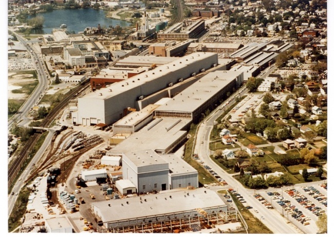
The Pittsfield plant from the east (circa 1970) Building 9 (High Voltage Laboratory) is the two-level building in the foreground; behind it is Building 14 (Tank Shop), and to its left is Building 100. Silver Lake is at the upper left. courtesy of Robert Mottershead, Pittsfield, MA
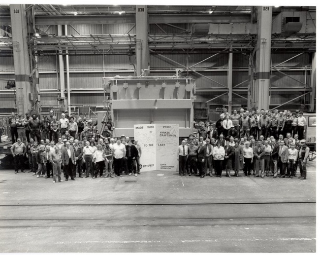
The last transformer built in Building 100 (October 30, 1987) This was one-half of a "small" phase-shifting transformer for the Boston Edison Company; it was actually the next to last transformer to leave Building 100. The last one was a unit which had been returned to be repaired by TVA (Tennessee Valley Authority).
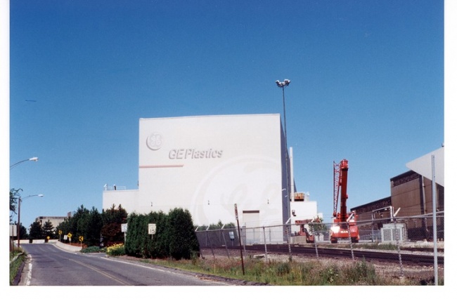
East end of Building 100 in 1996; photo by author
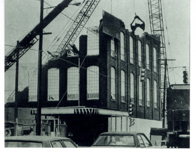
Building 28 being razed in 1988 Berkshire Eagle, April 30, 1988
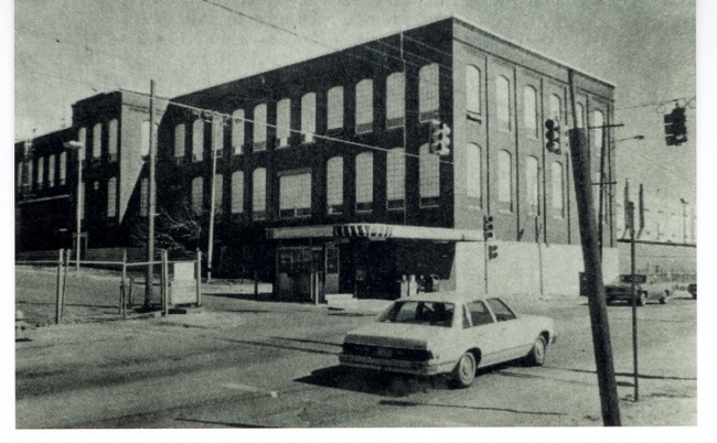
South Gate along East Street in 1988 Berkshire Eagle, March 23, 1988
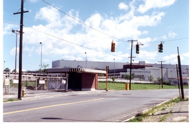
South Gate along East Street in 1996; photo by author
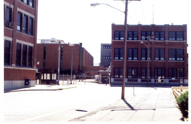
Building 16 and North Gate in 1996; photo by author
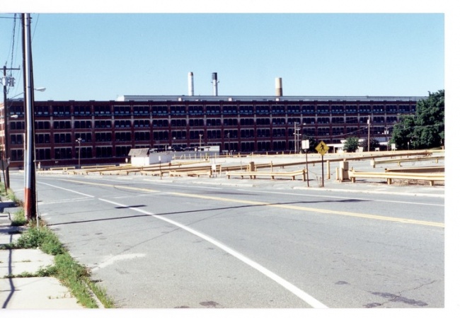
Buildings 42 and 43 in 1996; photo by author
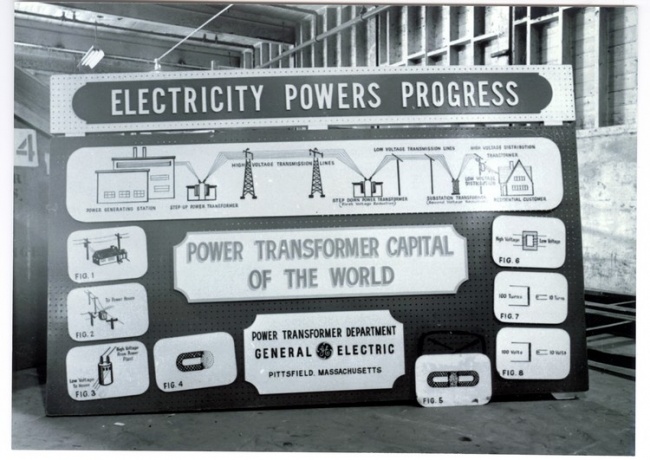
"Power Transformer Capital of the World" (Pittsfield, Mass.); courtesy of General Electric Company (1975)
To read more, continue to Transformers at Pittsfield, part 2.


.jpg)
.jpg)
.jpg)
.jpg)


.jpg)
.jpg)


.jpg)
.jpg)


.jpg)
.jpg)
.jpg)
.jpg)
.jpg)
.jpg)
.jpg)
.jpg)
.jpg)
.jpg)
.jpg)
.jpg)
.jpg)
.jpg)
.jpg)
.jpg)
.jpg)
.jpg)
.jpg)
.jpg)
.jpg)
.jpg)
.jpg)
.jpg)
.jpg)
.jpg)

.jpg)
.jpg)

.jpg)
.jpg)

.jpg)
.jpg)

.jpg)
.jpg)

.jpg)
.jpg)
.jpg)
.jpg)
.jpg)
.jpg)


.jpg)
.jpg)
.jpg)
.jpg)


.jpg)
.jpg)
.jpg)
.jpg)
.jpg)
.jpg)
